PROCEEDINGS OF THE 5TH INTERNATIONAL CONFERENCE ON ADVANCED RESEARCH ANO RAPID PROTOTYPING, LEIRIA, PORTUGAL, 28 SEPTEMBER- 1 OCTOBER, 2011
Innovative Developments in Virtual
and Physical Prototyping
Editors
Paulo Jorge Bártolo
Ana Cristina Soares de Lemos
Ana Patrícia Oliveira Tojeira
António Mário Henriques Pereira
Artur Jorge Mateus
Ausenda Luís Avelar Mendes
Cyril dos Santos
Dino Miguel Fernandes Freitas
Helena Maria Bártolo
Hem·ique de Ammim Almeida
Igor Marques dos Reis
Juliana Rosa Dias
Marco André Neves Domingos
Nuno Manuel Fernandes Alves
Ruben Filipe Brás Pereira
Tatiana Marisa Fernandes Patrício
Teima Margarida Dias Ferreira
Centre for Rapid and Sustainable Product Development
Polyteclmic Institute of Leiria, Portugal
0
~'~~,~~~~~"'
Boca Raton London New York Leiden CRC Press is an imprint of theTaylo r & Francis Group, an Informa business
lnnovative Developments in Virtual and Physical Prototyping- Bártolo et ai. (eds)
© 2012 Taylor & Francis Group, London, ISBN 978-0-415-68418-7
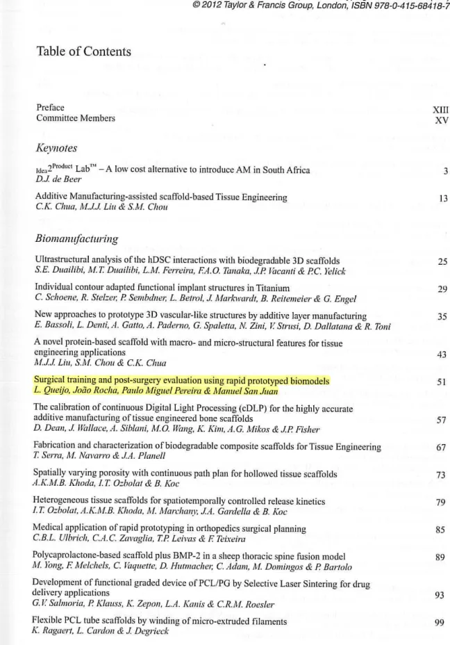
Table
of Contents
Prefacc
Committce Members
Keynotes
Idc:.2Product Labm- A low cost alterna tive to introduce AM in South Africa D.J. de Beer
Additive Manufacturing-assisted scaffold-based Tissue Engineering
C.K. Cima, M.JJ. Liu & S.M. Chou
Biomanujàcturing
Ultrastructural analysis ofthe hDSC interactions with biodcgradable 30 scaffolds
S. E. Duailibi, M. T. Drwilibi, L.M. Ferreira, F.A.O. Tanaka, .JP. Vacanti & P.C. Yelick
Individual contour adapted functional implant structures in Titanium
C. Sclroene, R. Stelze1; P. Sembdne1; L. Betrol, .J Markwardt, B. Reitemeier & G. Engel
New approaches to prototype 30 vascular-like structures by additive layer manufacturing
E. Bassoli, L. Denti, A. Gatto, A. Pademo, G. Spaletta, N Zini, V. Stmsi, D. Dallatana & R. Toni
A nove! protein-based scaffold with macro- and micro-structural features for tissue engineering applications
M..J.J Liu, S.M. Chou & C.K. Clwa
Surgical training and post-surgery evaluation using rapid prototyped biomodels
L. Queijo, João Rocha, Paulo Miguel Pereira & Manuel San Juan
The calibration of continuous Digital Light Processing (cDLP) for the highly accurate additive manufacturing oftissue engincered bone scaffolds
D. Dean, .J Wallace, A. Siblmri, M.O. Wang, K. Kim, A.G. Mikos & .JP. Fisher
Fabrication and characterization ofbiodegradable composite scaffolds forTissue Engineering
T. Serra, M. Navarm & .IA. Plcmell
Spatially varying porosity with continuous path plan for hollowed tissue scaffolds
A.K.M.B. Khoda, I.T. Ozbolat & B. Koc
Heterogencous tissue scaffolds for spatiotemporally controlled release kinetics
I. T. Ozbolat, A.K.M.B. Klrnda, M. Marchany, .IA. Gardella & B. Koc
Medical application ofrapid prototyping in orthopedics surgical planning
C.B.L. Ulbrich, C.A.C. Zavaglia, T.P Leivas & F. Teixeira
Polycaprolactonc-based scaffold plus BMP-2 in a sheep thoracic spine fusion modcl
M. Yong, F. Melchels, C. Vaqu ette, D. Hutmaclre1; C. Adam, M. Domingos & P. Bartolo
Dcvelopment of functional graded device of PCL/PG by Selectivc Laser Sintering for drug delivery applications
G. V Salmoria, P. Klcmss, K. Zepon, L.A. Kmris & C. R.M. Roesler
Flexible PCL tube scaffolds by winding ofmicro-extruded filaments
K. Ragaert, L. Cardan & .J Degrieck
v
XIII XV
3 13
25
29
35
43 5 1
57
67
73
79
85
89
93
lnnovative Deve/opments in Virtual and Physica/ Prototyping- Bártolo et a/. (eds)
©
2012 Taylor & Francis Group, London, ISBN 978-0-415-68418-7Surgical training and post-surgery evaluation using rapid
prototyped biomodels
Luís Queijo
&
João Rocha
Instituto Politécnico de Bragança. Bragança, Portugal
Paulo Miguel Pereira
Serviço de Neurocimrgia do Ho5pitaf de S. Jotio, Porto. Portugal
Manuel San Juan
ESTII- Universidad de J álladolid; CIBER- Centm de lnvestigación Biomecánica y Ergonomia, Valladolid, Spain
ABSTRACT: The biomedical use of Rapid Prototyping Technologies (RP) had great developments in lhe las! years, especially as supportive tools for tissue growth, direct or supportive technology for implant fabrication or as too! for personalized biomodels production applied to studies, this research will foc us on this last type of usage in continuation of previous work developed with RP as an aid of surgery procedures. Biomodels can play an important role as a complementary diagnostic method to medical staff (Queijo et ai. 20 I 0). The usage of RP technologies for biomodels production, in Lytic Spondylolisthesis surgical training andas a too! for post-surgery evaluation, is presented in this paper.
INTROOUCTION
30 replicas of vertebral spine sections are useful in diagnosing, planning and surgery simulation, visual-ization and manipulation. To patients it is important, allowing them to understand their pathologies nature, surgi cal proceedings perfom1ed by surgeon (Madrazo ct ai. 2008) as well to reduce anxiety facing surgery need (Queijo et ai. 20 I 0). ln this study it will be presented a procedure to manufacture the needed biomodels to fu lfill these requirements. These allowed a better support to surgery practice by a previous analysis to the patient condition in the form of a segmented biomodel and the surgery planning by a biomodel representing the corrected spine section and thc medical devices applied.
Ali physical biomodels were constructed based in the 30 digital models reconstructed from paticnt CT (Computerized Tomography) scans, where imagc segmentation teclmiques were performed.
The manufacturing technique uscd was Three Dimensional Printing (TDP) once this technique can provide the needed resolution and surface f inishing nccded to proper visualization and manipulations, associated to a manufacturing low cost.
1.1 Lytic spOiu(l•lolisthesis
With bipedal posture most of the loads transmitted to lhe lumbar spine pass through the posterior elemcnts of the vertebrae. Thc isthmus (pars intcrarticularis) is the
51
thinner part of the posterior vertebral arch and hence, the least rcsistant to fatigue.
Accordingly, stress fracture ofthe isthmus is a com-mon occurrence acom-mong young active adults and partic-ularly, among participants in some sports like diving, swimming, weightlifring, gynmastics and running.
With this fracture the vertebral body, pedicle and superior articular processes become separated from lhe inferior articular processes and hencc from the ver-tebra below. This condition creates the possibility of slippage between the vertebrae.
The term spondylolisthesis is used to identify the anterior translation in the sagittal plane of a vertebra (and the spine above it) relative to thc vertebra below. There are severa! aetiologies but the lytic or isthmic type, as described above, is the most common. ln a lytic spondylolisthesis there is a bilateral defect of thc isthmus (pars interarticularis).
The sl ippage betwcen the vertebrae can cause the exiting nerve roots (the nervcs exiting the spinal canal at this levei, through the intervertebral foramina) to be squeezed causing leg pain and difficulty in walking. When this occurs, a surgical trcatment may be neces-sary to dccompress the nerves and stabilize the spinal segment (to avoid further slippage) with or without reduction ofthe deformity.
1.2 From CT images to 3D digitalmodels
fi le can have severa! proveniences, most commonly segmentation image or CAD software. As this last one allows the manipulation of 3D digital modcls by adding, subtracting or changing some of his fcatures, thc first ones are essential to perform image recon-struction and obtain the digital models ITom 20 image data files.
Most ofthese images come from CT or MRI scans in the form of cross sectional images ITom the study arcas, according human axis (axial, coronal and sagit-tal) and obeying to the international standards in Digital lmaging and Communications in Medicine -DI COM.
Models quality is directly connected with the inter-val between images that is also a compromising solu-tion between object structure size and the amount of radiation to which the patient is subjected.
30 digitalmodels are obtained reeurring to image segmentation techniques where severa! operations are performed in arder to distinguish the main object -bane structures, in this case, from the main tissues by the application ofmasks according with the gray gra-dient in Hounsfield scale (HU). These masks allow a posterior rendering process that reconstructs the structure in a tridimensional image.
1.3 Rapid prototyping- three dimensional printing
Thc logical following step after the 3D digital model rendering is the fabrication of the physical biomodel that will allow a better v isualization allied to h is manip-ulation. The technology applied to this fabricat ion is rapid prototyping, often called additive manufac-turing or fabrication that represent a new group of non-conventional teclmiques introduccd in the medi-cal field and providc high reproducibility and elevated capacity to quickly produce very complex 30 shapes (Gibson 2006) (Bártolo et ai. 2009).
Once 30 digital model is obtained, his forro is exported in the formal of a .stl file where ali the sur-faces are converted into a triangle mesh allowing to be imported by any 30 print manager software. Next step is a hidden process where the print manager divides lhe model contained in the .stl file in severa( si ices that are re-encoded and will constitute anothcr file type that is sent to the printer- a .sli file.
Manufacturing processes available today, as Fused Deposition Modeling (FDM), Stereolithogra-phy (SLA), Selective Laser Sintering (SLS), Tridi-mensional Printing (TDP or 3DP) and Laminated Object Manufacturing (LOM) among other specific processes, bring a wide range of choice over building materiais and outcome biomodel mechanical charac-teristics, as well as costs. A more detailed dcscription ovcr each one of this processes and over biomodeling process can be found in prcvious work (Queijo et ai. 20 10).
Despite severa( rapid prototyping techniques avail-able, each one with h is own characteristics, thc chosen to produce these biomodels have been thrcc dimen-sional printing (TDP) in the variation from ZCorp®.
Figure I. ZCorp's TDP printcr in action.
This process allows biomodels fabrication with good visualization characteristics, manipulation possibility and with a cost that is substantially lower than other alternate methods.
ZCorp's TDP technique uses a composite powder as building material bonded by an aqucous media that is jct1ed by a printing head, similar to any 20 printer, as can be seen in figure I. Once the models are built some stability must bc provided to thc surfaces (that are pulverous) in order to give rigidity and manipula-tion ability. This stabilizamanipula-tion is, usually fulfilled by the impregnation with another bonding media such as cyanoacrylate.
1.4 Medical case descripticm
The images bclong to a 30 year-o ld malc complaining of bilateral pain al ong the inferior limbs progressing over the past 5 years.
The imaging studies yielded a bilateral LS isthmic lysi s and an anterior slip of L5 ovcr S I of about 50% of the superior endplate of S 1 (lytic spondylolisthe-sis). Moreover, there was a small posterior slip of L4 over LS. Together, thcsc two slips result in an anterior translation ofthe vertebral body ofL5 compared to L4 and S I.
ln face of a progressive clin ical course, a surgi-cal treatment was proposed to the patient in arder to decomprcss the nerve roots and to f ix the vertcbrae, avoiding further slips among thcm.
good Jility Jther
wder 1 that intcr, built (that Jula-·d by
:h as
ning ;sing
h mie
50% sthe-•f L4 erior oL4 urgi-er to Jrac, L5-iand rews ln c,
ly in d to per-·onic wcrc were :rted
nter-:d to
Figure 2. lmage segmcntation - Rcndcring without mask processing.
the L5 screws through the Scxtant'" Reduclion"' sys-tem in arder to try lo achieve a bctter sagittal alignmcnt ofthe vertebrac.
ln thc poslopcrativc CT scan wc found an appro-priate placcment of lhe implants, but a very limited correction ofthc dcformity.
2 METHOOOLOGY
Along methodology description, each biomodcl pro-duction phasc is intercalatcd with lhe facls related in medical description. For better contextuai ization it was dccidcd to divide thcmes.
Ethically, patient should provide authorization for TC imagcs to be used and these should be, as soon as the proccss allow, madc anonymous (once TC sys-tcms registe r paticnt's information). ln this process, 20 imagcs are importcd lo segmcntation software whcre will be trealed to rebuild the dcsired spinal arca.
2.1 lmage segmentation
First of phascs in thc procedurc consists in defin-ing gray valucs interval corrcsponddefin-ing to HU unils in Hounsfield scale to iso la te the maximum of our object ofwork - the section ofspine, including L3, L4 and L5 vertcbme and most of sacrum. As first iteration, have been adopted a range of values defined as standard lo bone tissue and set bctween 226 and 11 96 HU. This process creatcd a mask that has covered cach imagc pixel which value is included in the chosen range and paintcd it in a selected calor. Rendcring proccss based on the created mask showed us that despi te the chosen range is dose to the desired, once has rcjected most of the unwantcd surrounding tissues there still hav-ing some adjustments to be madc bcfore followhav-ing to the next step - figure 2. Range HU values where then settled betwecn 200 and 1196.
Thc following step consisted in rectifying each structure, frame by frame until a coherent digital model
53
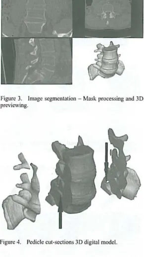
Figure 3. lmagc scgmcntation - Mask proccssing and 30 prcvicwing.
Figure 4. Pcdiclc cut-scctions 3D digital model.
is carried out, as seen in figure 3. Unwanted structures as CT table and iliac bone showed in figure 2 have been removed once those are irrelevant to the study.ln this process and to allow a bettcr and individualizcd visualization we havc decide to iso latc each one ofthe structures with an individual mask.
Afier obtained the reconstructed 3D digital model it is already visiblc the constriction in L5-S I conjuga-tion holes as well as thc front slippage of L5 vertebra. This way, it was dccided to produce a biomodel with ped iclc cut sections where thc constriction and thc slippage could be bctter obscrved. Digital model have bcen manipulated by orthogonally cutling ali masks in L5 pcdicle regions. The rcsult can be secn in figure 4
wherc criticai arcas are markcd .
Once 30 digital model is fully dcfincd it has bccn exported as a .stl file and manipulated by 30 print managcr.
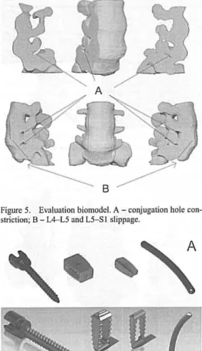
2.2 Emluation biomodel
Figure 5. Evaluation biomodcl. A- conjugation hole con-striction; B - L4-L5 and L5-S I slippage.
Figure 6. Multiaxial pediclc scrcw, PEEK cagcs and lon-gitudinal rod: A - real devices; B - 3D modclcd dcvices.
Once settled building paramelcrs, biomodel fabri-cation is done, laycr by layer, foltowed by surfaccs sta-bilization as final procedure, as described in previous work (Queijo et ai. 2010).
Through physical biomodel, shown in figure 5, has been visualized patient condition in the constricted conjunction holes and vertebra slippage and evaluated possible pedicle vertebral screw-bars insertion points and angulations that would bring L5 vertebra to a most favorable position.
Also, this model has been shown to the patient to explain him the nature of his pathology and the need for a surgery where the lower vertebrac would be fixed with medical devices, represented in figure 6.
2.3 Surgical planning biomodel
After those definitions, with previously CAD modeled pedicle screws, PEEK cages and longitudinal rods, in
54
Figure 7. Surgical planning 3D digital model.
Figure S. Medical dcvice pos itioning validation biomodel.
Figure 9. Validation biomodel de tails: A - criticai nerve root arcas; B - PEEK cagcs positioning; C - Possiblc face! remova! arca; D- Pedi ele scrcw orientation and positioning.
3D CAD software (figure 6) and exported to .stl files, all bone structures are repositioned.
As defíned previously, vertebrae repositioning is done to altow a bigger clearance in the conjugation boles and a reduced slippage between L4-L5 and L5-S I anel, then, matched with medical devices resulting in a complete 3D digital model as sown in figure 7 that havc been built for a new evaluation and positioníng validation (figure 8).
ode!.
lCTVC face! ning.
·iles,
.g is ttion L5-.ting
that ning
e to Jone Jval, .tion ·bral
Figure I O. Pos t-surgcry biomodel.
A
8
c
Figure 11 . Post-surgcry biomodcl details: A - PEEK cagc fixing L4-L5 vertcbrac; B - Facet and partia) pedi ele remova) to allow cage positioning; C - Pcdiclc screw implants with longitudinal rods.
2.4 Post-surgery biomodel
Post-surgery biomodel (figure 10) is obtained follow-ing the sarne procedure as for evaluation biomodel. Based in patient post-surgery TC images, 30 digital modcl has been reconstructed with the particularity of being needed two distinct range in Hounsficld scale-one for the bscale-one, as settled previously and another to metallic medical devices settled in 1400-2976 HU. Reconstruction, in this case, become harder once therc is a considcrablc presence of noise in TC images, duc to the ray dispcrsion in presence ofmetallic devices.
Once combined lhe two masks generated for bone and for metal, lhe rcsult is a 30 digital model that is exportcd to a .stl file and then fabricated. This bi omodel allow a comparison between what has been planned and what was achieved in the surgery due to ali conditionings. Figure li shows the details in post-surgery biomodel.
3 CONCLUSIONS ANO FURTHER WORK
As prcviously dcmonstrated, through rapid prototyping technologies anda multidisciplinary collaboration it is possible, in a short pcriod oftime, to build biomodels
55
Figure 12. Biomodel comparison front vicw: pre-surgcry (lcfl) and post-surgcry (right). A - PEEK Cage placcmcnt !lctail.
Figure 13. Biomodcl comparison lcfl view: prc-surgcry (lcft) and post-surgcry (right). A- pcdicle screw positioning; B - conjugation hoJe clearance.
allowing not only a complementary diagnose method for 30 visualization ofcomplex arcas but also valuable tools for surgical applications.
ln this case, it has been possible to show evalua-tion biomodel to the patient and explain, supported by a simplified form of visualization, lhe cause of pain and the reason ofsurgcry need. Patient becomes aware that the only way to relief long time pain was fi xing vertebrae to avoid a continuous degeneration of his condition.
Another advantage of biomodels is their uses as a complimentary diagnose allowing medical staff to observe medical images in a 30 way.
Patient condition was properly defined through evaluation biomodel that enabled to identify lhe amount of slippage betwecn L4-L5 and L5-S I verte-brae as well the compression in lhe nerve roots caused by this slippage that constricted conjugation holes. lt then becomes clear that it would be difficult to bring L5 vertcbra close to a satisfactory position.
Through positioning biomodel were defined ade-quate insertion points and the needed orientation to pedicle screws. Also, in this case, were defined which bone structures needed to be removed to allow pro per cage insertion as well the necded vertebra reposition-ing. lt becomes more or less clear that nerve root decompression would be achieved not ali by verte-brae repositioning but also by bone structures remova! (right L5 pedicle and facet) as can be seen in figure 9 detail C.
medium 3 mm increasc in axial vertebrae distance but that was granted the necded conjugation boles clcarance to fully decompress nerve roots.
Furthcr work will focus in thc cvaluation and surgery planning biomodcls in ordcr to makc thcm as functional as possiblc. lfsucceeded, this will allow the inclusion of real medical devices directly in biomod-els as a simplified form of simulating surgcry phase ofmedical dcvices placement.
This typc ofsurgery becomes frequently dependent on surgeon's dccisions and unknown factors occurring during surgery, so therc is a need to investigate further cases with personalized manufacturing tools to allow proper pediclc screw placcment and oricntation, also known as surgical guide.
REFERENCES
Búrtolo, P. J. S. , Almeida, H. & Laoui, T. 2009. Rapid proto-typing and manufacturing for tissue engineeri ng scaffolds. lnt. J. Comput. Appl. Tcchnol., 36, 1-9.
G ibson, I. 2006. Rapid prototyping: from product dcvel-opment to medicine and bcyond. Virtual and Physical ' Prototyping, I, 31 -42.
Madrazo, 1., et ai. 2008. Stereolithography in spinc pathology: a 2-case report. Surgical Ncurology.
Queijo, L. et ai. 2009 . A prototipagem rápida na modelação de patogcnias. 3.• Congresso Nacional de Biomecânica. Bragança. Porh1gal.
Queijo, L. ct ai. 20 I O. A surgical training model manufacture using rapid prototyping technology. Innovative Develop-mcnts in Dcsign and Manufacturing-Advanced Rcscarc h in Virtual and Rapid Prototyping, 175- 179.