Jehad Ahmad Yamin
[email protected] University of Jordan Faculty of Engineering & Technology Mechanical Engineering Department Amman 11942, JordanMohammad Ahmad Hamdan
[email protected]University of Jordan Faculty of Engineering & Technology Mechanical Engineering Department Amman 11942, Jordan
The Performance of
Hydrogen-Powered 4-Stroke SI Engine Using
Locally Designed Fuel Regulator
In this work, the performance of a spark ignition engine powered with hydrogen fuel was studied and compared with gasoline fuel. Hydrogen fuel was used, using a locally made stainless steel gaseous regulator which was designed and installed in engine. This regulator was located between the engine and the hydrogen fuel cylinder, and it is triggered by the suction pressure and hence it keeps the fuel supply lines open under negative pressure only, which exists under no leak conditions and when the engine is running. It was found that the engine runs smoothly with the regulator in place. Further, it was found that the brake power and the volumetric efficiency of the engine drop down when the engine is powered by hydrogen, while the specific fuel consumption is drastically improved (by almost one-third) when hydrogen is used as a fuel. Finally, the thermal efficiency remains almost the same in both cases of fuels.
Keywords: hydrogen fuel, hydrogen powered engine, gaseous fuel regulator, engine
performance
Introduction
1Fossil fuels, which meet most of the world today, are being
depleted rapidly. Also, their combustion products are causing global environmental problems, such as the greenhouse effect, ozone layer depletion, acid rain… etc. These changes to the earth’s ecosystem pose great danger to our environment and life on earth. Engineers and scientists agree that the solution to all of these global problems would be to replace the existing fossil fuel systems with the more eco-friendly fuel systems. Hydrogen presents one such great alternative solution. It is a very efficient and clean fuel; its combustion produces no greenhouse gasses, no ozone layer depleting chemicals, and little or no acid rain ingredients and pollution.
Hydrogen was used as fuel in internal combustion engines during the late 1800’s by Picardo who was able to achieve high thermal efficiencies with hydrogen powered internal combustion engine (Richardo, 1923).
Hydrogen proved promising alternative to gasoline owing to two major factors: the almost near-zero engine-out emissions and higher thermal efficiencies which in some cases exceeded those values for conventional petrol-fuelled SI engines (Swain et al., 1981; Tang et al., 2002; and Das, 1991).
These unique combustion characteristics of hydrogen that allow clean and efficient operation at low engine loads present difficulties at high engine loads. These problems resulted from the detonation of the hydrogen-air mixture as a result of low ignition energies. This factor triggers frequent unscheduled combustion events, accompanied with high combustion temperatures of mixtures near stoichiometric ratios leading to increased NOx production and thermal as well as mechanical stresses on the engine components.
According to the best estimates, the world’s fossil fuel (coal, petroleum and natural gas) production, which meets about 80% of our energy requirements today, will start to decline in 20-30 years time. The petroleum and natural gas production is already decreasing in parts of the world like United States. On the other hand, since the demand for energy is ever increasing as the nations of the world try to improve their living standards; alternative energy sources are being considered. Research regarding their conversion into usable forms of energy is being accelerated.
Paper accepted May, 2010. Technical Editor: Demétrio Bastos Neto
Reviewing the literature one finds voluminous amount of literature and reviews discussing the use of hydrogen as an automotive fuel, some of which dates back to more than one hundred years. Some of the greatest and comprehensive reviews compiled in this area are those written by Veziroglu (2007), Bal and Wietschel (2008), White et al. (2006), and Das (1990). They not only discussed the major effect of utilizing hydrogen as H2ICE fuel, but also they discussed the major difficulties, technical problems and economy of utilizing hydrogen as fuel for IC engines.
Further, Billings et al. (1966) have modified and tested a hydrogen-powered vehicle. The modification included the installation of a gaseous-type carburetor modified to accommodate hydrogen, accompanied by a water injection system to cool the combustion flame and to quench the hot spots within the cylinder which can cause backflashing. Further, the modification to overcome the backflashing problem included the installation of stainless steel spark plugs and the decreasing of the spark gap. Finally, they compared the performance of hydrogen powered engine with that powered by gasoline fuel; they found out that the hydrogen driven engine was an average of 21% more efficient than the corresponding gasoline-powered one.
The effect of compression ratio, surface/volume ratio of combustion chamber, and the boost pressure on thermal efficiency and exhaust emissions were investigate by Yasuo et al. (2000), as they used a hybrid electric vehicle with internal combustion engine fueled with hydrogen. They found that a decrease in the surface/volume ratio may result in a maximum increase in the indicated thermal efficiency by 44%. NOx emission was found to be less than 10 ppm.
The Gaseous Regulator
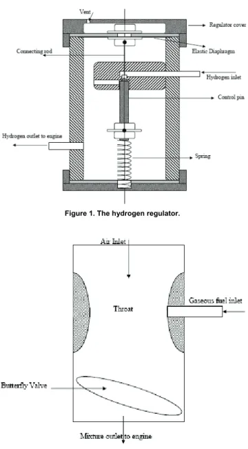
The regulator shown in Fig. 1 is made up of stainless steel coated with a chrome layer that would prevent any chemical attach on the body of the regulator. It is located between the engine and the compressed hydrogen cylinder. It is attached to a throat placed at the inlet of the engine, as shown in Fig. 2.
Figure 1. The hydrogen regulator.
Figure 2. The inlet manifold device.
This regulator is triggered by the suction pressure created at the throat as a result of air flow past the throat area.
Initially the control pin, which is of conical head geometry, is set such that the pressure caused by the stiffness of the spring (upwards) balances the pressure from hydrogen at the inlet (from hydrogen cylinder). When the throttle valve at the inlet manifold is opened, air flows past the throat area causing the pressure to drop below atmospheric values.
This suction pressure causes the elastic diaphragm of the regulator to deflect downward, thus opening the inlet line for hydrogen flow. This keeps the fuel supply lines open under negative pressure only. Hence, no leak occurs and if it does, air will leak into the supply lines instead of hydrogen leaking outside.
When more fuel is required by the engine, butterfly valve is opened and more air passes through the throat causing more pressure drop at the regulator outlet. As a result, the pressure inside the regulator decreases causing the diaphragm to deflect downward and hence the connecting arm pushes the needle downward to allow more fuel to flow into the engine.
The reverse action occurs when less fuel is required by the engine or when the vehicle is suddenly brought to rest or the accelerator paddle is released.
Further, the regulator will eliminate the occurrence of backfire or fire spreading into the supply lines through the following mechanisms:
1. The inlets and outlets of the regulator are designed based on the quenching diameter of hydrogen.
2. The supply lines will always convey hydrogen ONLY IF suction pressure acts on the diaphragm, and
3. The spring will help shut the supply lines if the suction pressure is lost either due to fire or sudden brake or closure of the throttle valve in the inlet manifold.
Flame Trapper
This part was used in the experiment as additional safety to conduct this experiment. It is called the flame trapper. It is located between the hydrogen cylinder and the regulator and its main function is to quench the flame in the case of backfire. It consists of water bath, as shown in Fig. 3, half filled with water and the hydrogen is introduced at the bottom of the bath and accumulated at the top. The regulator inlet is directly connected to the top of this bath. In case of a flashback, the flame will be quenched inside the flame trapper before it reaches the cylinder.
Figure 3. The flame trapper setup.
The Engine
To be able to use the engine with gaseous fuel, a special mixer which consists of a throat and butterfly valve only is fitted in place of the carburetor to control the flow of fuel. The gaseous fuel is introduced through a hole at the tip of the throat. The engine testing conditions were as shown in Table 1, below.
Table 1. Engine test conditions.
Engine Parameter Value
Engine speed 1500-2500 rpm
Compression Ratio 9:1 (fixed)
Spark Advance Variable
Throttle Position Wide Open (WOT)
Experimental Procedure
As an initial step, the regulator was tested for any leaks. This test was performed after it was installed between the engine and the hydrogen cylinder. During two hours of testing under a pressure of two atmospheres, no leak was detected.
Having carried out the leak test, the next step was to estimate the performance of the engine with hydrogen as fuel and compare its relative performance with gasoline.
Results
It is to be mentioned here that during the experimental work carried out, the engine was running smoothly with neither knocking nor leak of hydrogen.
Figure 4 shows the volumetric efficiency for both gasoline and hydrogen fuels. First thing noticed is the reduction in the engine volumetric efficiency with hydrogen fuel. Similar results were shown by others like Furuhama et al. (1978). This is expected since the inlet manifold is usually supplied with some heat to help vaporize the liquid (gasoline) fuel. Therefore, hydrogen gas expands more than liquid gasoline inside the engine, leading to a drop in the volumetric efficiency of a hydrogen fired engine. Further, the displacement of air by the large volume (expanded) hydrogen occurs due to heated inlet manifold. It was found by researchers that a stoichiometric mixture of Hydrogen-Air fuel contains approximately 30% hydrogen by volume, whereas for gasoline-air stoichiometric mixture the percentage is 20% of fully vaporized gasoline by volume.
This result was also shown by many other researchers and was corrected by certain modifications such as separating the inlet from the outlet manifold, using hydrogen fuel injectors, cooling the inlet manifold for the hydrogen engine.
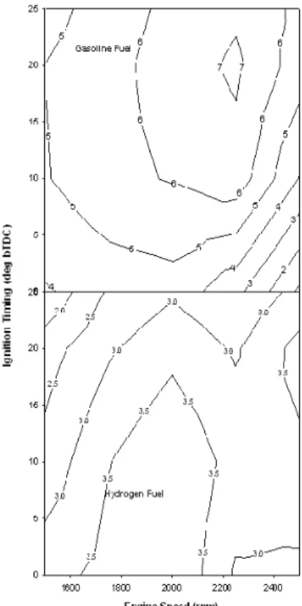
Figure 5 indicates the relation between the brake power and the speed of both the hydrogen and gasoline fired engines at different engine speeds and ignition timing. As shown in the figures, the brake power generated by hydrogen is less than that generated when gasoline is used. This is expected since the volume efficiency of hydrogen-fuelled engine is lower than that for gasoline-powered engines.
Further noticed is that the peak brake power values for hydrogen tends to occur at spark timings less (i.e. retarded) than those for gasoline. This means that with hydrogen as fuel, the engine spark timing must be retarded (brought near to top dead center) compared with gasoline. This is the direct result of the faster burning of hydrogen compared with gasoline.
Similar trend is also present in Fig. 6, which shows the reduction of engine torque when using hydrogen compared with conventional gasoline fuel. Same reason can be said as that for the brake power. Further, this figure suggests that the MBT (maximum brake torque) angle for hydrogen is near the top dead center compared with gasoline.
Figure 4. Variation of volumetric efficiency (%) with engine speed at various ignition timing.
Figure 6. Variation of brake torque (N-m) with engine speed at various ignition timing. 15 15 12 12 9 6 21 21 21 21 18 18 18 24 24 24 24 24 27 27 27 27 27 27 27 Ig ni tio n T im in g (deg b T DC) 0 5 10 15 20 25 24 24 21 24 24 24 24 24 21 21 21 21 27 27 27 27 27 30 18 15
Engine Speed (rpm)
1600 1800 2000 2200 2400 0 5 10 15 20 25 Gasoline Fuel Hydrogen Fuel
Figure 7. Variation of brake thermal efficiency (%) with engine speed at various ignition timing.
The thermal efficiency of the hydrogen powered and gasoline powered engines is shown in Fig. 7. As shown in this figure, the
hydrogen powered engine has higher efficiency than that of gasoline and this is in agreement with all previous results. Obviously and as shown, the thermal efficiency for both cases has the trend of variation with speed. These values can be further improved if the compression ratio of the engine is increased. This is due to the higher RON (Research Octane Number) of hydrogen of about 120 (Swain et al., 1981 and Topinka, 2004) compared with gasoline of about 91-99 (Heywood, 1988). In addition to his factor, the low lean-flammability limit of hydrogen (about 0.1≤Φ≤7.1) compared with gasoline (about 0.7≤Φ≤4) with Φ is the equivalence ratio.
Those two factors help attain higher values of thermal efficiency. However, in this study the compression ratio was kept constant for the sake of comparison only.
Further, it is shown that the peak thermal efficiency for hydrogen occurs at retarded spark timings corresponding to higher engine powers compared with gasoline.
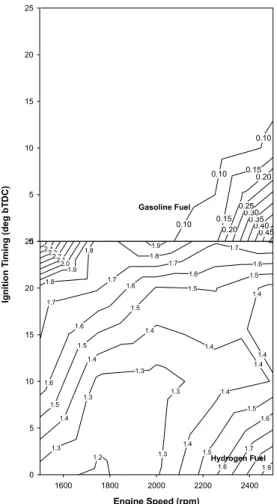
The variation specific fuel consumption with speed is shown in Fig. 8. It is very clear that the utilization of hydrogen as a fuel leads to significant drop in the specific fuel consumption (on mass basis), which is considered one of the main advantages of using hydrogen as a fuel in internal combustion engines.
0.85 0.75 0.65 0.65 0.55 0.55 0.45 0.45 0.45 0.35 0.35 0.35 0.35 0.35 Ig niti on T imin g (d eg bT D C ) 0 5 10 15 20 25 0.16 0.14 0.12 0.12 0.14 0.14 0.14 0.14 0.14 0.12 0.12 0.12 0.12 0.12 0.16 0.10 0.20 0.18 0.16
Engine Speed (rpm)
1600 1800 2000 2200 2400 0 5 10 15 20 25 Gasoline Fuel Hydrogen Fuel
Figure 8. Variation of brake specific fuel consumption (kg/kw-hr) with engine speed at various ignition timing.
As shown in the figure, the specific fuel consumption of a hydrogen powered engine is almost independent of speed, for the speed test range in this work, while it increases at certain speed for a gasoline fired engine. Further. The specific fuel consumption of a hydrogen engine is almost one third of that for a gasoline fired engine.
basis. This figure shows the variation of the brake specific energy consumption in m3/kw-hr, rather than the ordinary kg/kw-hr. Due to the lower density of hydrogen, the energy density on volume basis that was consumed by the engine was much higher than that for gasoline (keeping in mind that the engine developed less output compared with gasoline).
Conclusions
1. From this work it may be concluded that the utilization of a new designed gas regulator in a hydrogen powered engine was very promising and the engine operated in a very smooth fashion.
2. The thermal efficiency of the engine is better when hydrogen fuel is used instead of gasoline.
0.45 0.40 0.35 0.30 0.25
0.20
0.20 0.15
0.15 0.10
0.10
0.10
Ignitio
n
T
im
ing
(de
g
b
T
D
C
)
0 5 10 15 20 25
1.9 1.8 1.7
1.6
1.6 1.5
1.5 1.4
1.4 1.7
1.7
1.7
1.7
1.6 1.6
1.6
1.6
1.6
1.5 1.5
1.5
1.5
1.5
1.4 1.4
1.4
1.4 1.4
1.4
1.4 1.3
1.3
1.3 1.3
1.3 1.9 1.8
1.2 2.42.3
2.2 2.12.0
1.9 1.8
1.8
Engine Speed (rpm)
1600 1800 2000 2200 2400 0
5 10 15 20 25
Gasoline Fuel
Hydrogen Fuel
3. The spark timing for hydrogen engine must be retarded to give better performance.
4. The engine tends to develop less power (and torque) with hydrogen fuel than gasoline engine.
5. Though the BSFC looks interesting, however, comparison based on BSEC shows more energy (per volume) needed to be supplied with hydrogen fuel.
References
Ball, M. and Wietschell, M., 2008, “The future of hydrogen – opportunities and challenges.” Int. J. of Hydrogen Energy; doi:10.1016/j.ijhydene. 2008.11.014. Billings, R.S. The hydrogen engine, A solution to pollution. 17m International Science Fair, Dallas, Texas, 1966.
Das, L.M., 1991, “Wxhaust emission characterization of hydrogen operated engine system; nature of pollutants and their control technique.”
Int. J. Hydrogen Energy, Vol. 16, pp. 765-775.
Das, L.M., 1990, “Hydrogen engines: a view of the past and look into the future.” Int. J. Hydrogen Energy, Vol. 15, pp. 425-446.
Furuhama, S., Hiruma, M., Enomoto, Y., 1978, “Development of a liquid hydrogen car.” Int. J. Hydrogen Energy, Vol. 3, pp. 61-81.
Heywood, J.B., 1988, “Internal Combustion Engine Fundamentals.” New York, NY: McGraw-Hill.
Ricardo, H.F. Further note on fuel research, Report of the empire motor fuels committee. Proc. IAE, 1923; 24.
Swain, M.R, Pappas, J.M., Adt Jr., R.R., Escher, W.J.D., “Hydrogen-fueled automotive engine experimental testing to provide an initial design-data base.” SAE Paper 1981; 810350.
Tang, X., Kabat, D.M., Natkin, R.J., Stockhausen, W.F., “Ford P2000 Hydrogen engine dynamometer development.” SAE Paper 2002; 2002-01-0242.
Topinka, J.A., Gerty, M.D., Heywood, J.B., Keck, J.C., “Knock behavior of a lean-burn, H2 and CO enhanced, SI gasoline engine concept.” SAE Paper 2004; 2004-01-0975.
Veziroglu, T.N., “21st Century's Energy: hydrogen energy system.” In:
Sheffield, J.W. and Sheffield, C. (eds), 2007, “Assessment of hydrogen energy for sustainable development.” Ed. Springer, pp. 9-31.
White, C.M., Steeper, R.R. and Lutz, A.E., 2006, “The hydrogen-fueled internal combustion engine: a technical review.” Int. J. Hydrogen Energy, Vol. 31, pp. 1292-1305.
Figure 9. Variation of brake specific energy consumption (m3/kw-hr) with
engine speed at various ignition timing. Yasuo, T., 2000, “Research and development of a hydrogen-fueled engine