Shielded Transceiver RF Coil Array for Simultaneous PET-MRI
E. Solis1,4, D. Tomasi1, S. Junnarkar3, D. Schlyer1, P. Vaska1, C. Woody2, J-F. Pratte3, P. O’Connor3, and A. O. Rodriguez4 1Medical Department,2Physics Department,3Instrumentation Division Brookhaven National Laboratory,
Upton, NY, 11973, The USA.4Centro de Investigacion en Instrumentacion e Imagenologia Medica, Universidad Autonoma Metropolitana Iztapalapa, Mexico, DF 09340, Mexico∗
Received on 17 April, 2008
The complementary information provided by combined MRI-PET modalities promises to facilitate metabolic investigations of complex physiological processes. We developed a radio frequency (RF) coil array that can operate in close proximity (2-mm radial distance) to a miniaturized PET camera insert for simultaneous PET-MRI of a rat brain at high magnetic fields (4 Tesla). All ferromagnetic components in the PET instrument were replaced with non-ferromagnetic components to minimize susceptibility artefacts in MRI, and optical fibres were used to connect the electronics of the PET camera to the acquisition system located outside the MRI scanner room. A passive electromagnetic shielding was developed to minimize the interference between the PET-electronics and MRI RF coil array. MR images of water phantoms and ”ex-vivo” rat brains were collected in two different conditions: with and without PET acquisition. Similarly, PET data was acquired in two different conditions: with and without MRI pulses (RF and gradients). The MR images showed good uniform sensitivity profiles for all cases and 66% decrease in SNR for the shielded case. The PET and MRI datasets demonstrated that the electromagnetic shielding successfully minimizes the RF interference between the instruments, minimizing MRI artefacts and protecting the delicate components of the PET electronics from MRI RF pulses.
Keywords: MRI coil array; Hybrid system; PET/MRI
I. INTRODUCTION
The ability to combine magnetic resonance imaging (MRI) and positron emission tomography (PET) is essential to study brain metabolism with anatomical precision [1-4]. While PET can map brain function and metabolism with low spa-tial resolution (2-10mm) using radioactive tracers, MRI can provide high-resolution anatomical maps with low functional and metabolic specificity. Thus the simultaneous PET-MRI acquisition aims to overcome the limitations of each individ-ual technique. However, a number of technical challenges have to be surmounted to successfully integrate PET and MRI because MRI is highly sensitive to magnetic field inhomo-geneities resulting from magnetic/metallic components of the PET camera and electromagnetic waves produced by the PET electronics, and PET is sensitive to the MRI fields and RF pulses. Because photomultiplier tubes cannot operate in the vicinity of the high magnetic fields [5-7], previous attempts to integrate PET and MRI used non-magnetic scintillating PET detectors in the MRI scanner bore that were connected to ex-ternal photomultiplier tubes through long optical fibres [8], which significantly reduce the efficiency for the detection of gamma rays [9]. Alternatively an MRI compatible PET insert could be based on a non-magnetic version of the miniatur-ized PET scanner for the conscious rat brain (RatCAP) [10-11]. Because the LSO scintillating crystals, silicon avalanche photodiodes (ADP), and the associated electronics performing front-end signal processing are highly integrated in this PET scanner (Fig. 1.b) can operate in high magnetic fields [12], photon carrying optical fibers connecting scintillating
crys-∗Corresponding author: Alfredo O. Rodriguez, [email protected]
tals and ADP-photodetectors are not needed. However, the close proximity (2cm) of the PET-electronics and the MRI RF coil leads to additional challenges because the digital signals in electronic modules of the RatCAP can introduce noise in MR images and the MRI RF pulses can affect the sensitive electronics of the RatCAP. Thus, the principal aim of this pa-per is to develop a mid-range saddle coil array (2-30 MHz-m) [13] for mouse imaging that allows to operate the RatCAP electronics and the MRI coil simultaneously with minimal in-terference at high magnetic fields (4 Tesla). Ex vivo and in vitro coil testing was performed with 4T whole-body MR im-ager. Phantom and rat’s brain images were acquired to demon-strate its viability to generate high quality images with stan-dard spin-echo sequences at high field MRI.
II. METHODS
A. MRI compatible RatCAP
re-FIG. 1: a). Schematic showing the experimental setup for simul-taneous PET and MR imaging showing the main components. The TSPM (Timestamp and Signal Processing Module) is the digital sig-nal readout module. b). Photo of the electronics architecture of Rat-CaP showing parts.
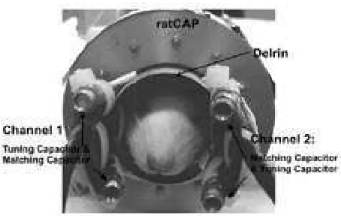
quired special non-magnetic pins, the APD sockets which had to be made without the steel pin sockets, a non-magnetic flex circuit board and non magnetic electronic components (e.g. solder leads). These components were shielded from the RF field by using a cylindrical aluminium housing surrounding the RatCAP. The Kapton cable carrying signals was shielded using copper tape. The entire data acquisition chain was then enclosed in an aluminium shield and set in the MR imager as shown in Fig. 2a) and 1a), respectively.
B. Electromagnetic modelling
The strong RF pulses used in MRI might interfere with the analog or digital signals (100 MHz clock) in the RatCAP and the RatCAP electronics can introduce RF noise in MRI. To avoid the interference between PET and MRI we used an elec-tromagnetic shielding encasing the RatCAP (Fig. 2.a). To estimate the effect of the shielding in MRI we calculated the RF magnetic field, B1, produced by the coil array using a fi-nite element method (FEM). Bi- and three-dimensional FEM models were used, to simulate the magnetic field for the un-shielded and un-shielded conditions. All numerical computations of the electromagnetic field produced by coil configurations were carried out with the commercial software tool FEMLAB (COMSOL, Burlington, MA, USA). The following dimen-sions were used: saddle coil parameters: inner diameter of the of 2.35 cm, length of 2.3 cm and thickness of 0.65 cm, Delrin parameters: inner diameter of the of 3.3 cm, length of 2.3 cm and thickness of 0.3 cm, Shield parameters: inner di-ameter of the of 3.7 cm, length of 2.3 cm and thickness of 0.3 cm. The values of the specific conductivity and relative
per-FIG. 2: Schematic diagram of transceiver coil array showing compo-nents and dimensions.
mittivity used for this calculation were those provided in the FEMLAB software: a) Saddle coils (copper): 5.998 107 S/m and 1 Q2/(Nm2), b) Electrical insulation (Delrin(): 0 S/m and 2.9 Q2/(Nm2), c) Shielding (aluminium): 3.774 107 S/m and 1 Q2/(Nm2), and d) the sample: 0.5 S/m and 80 Q2/(Nm2). Simulation parameters at 170MHz for a) saddle coil array, Delrin and no shielding: initialized mesh consists of 22759 elements, number of degrees of freedom: 34393, and solution time: 177.937 s. b) saddle coil array, Delrin and shielding: ini-tialized mesh consists of 22053 elements, number of degrees of freedom solved for: 34740, and solution time: 30.719 s.
C. Transceiver array coil
di-FIG. 3: Bi-dimensional maps of the magnetic field (B1) simulated with the FEM approach: a) the coil array, b) coil array and the Delrin ring, and c) the coil array, Delrin and the aluminium can.
ameter 2.5-cm, length 4-cm) filled with a 100-mM NaCl water solution, and the resonant frequencies were measured as the reflection coefficients (S11) by using a network analyzer and S-parameter test set (Model 4396A, Hewlett Packard, Palo Alto, CA, The USA), and quarter-wavelength coaxial cables. The resonant frequency,
f
, and its 3dB-bandwidth,∆f, were measured and the quality factorQ
of the coil array was deter-mined asQ=∆ff. The rough estimate of the images SNR was computed by taking a ROI within the images and outside the images, and diving the mean of each ROI. This is a very crude way to measure the signal-to-noise ratio (SNR).D. MRI acquisition
All experiments were carried out on a 4 Tesla Var-ian/Siemens MRI system equipped with a self-shielded whole-body SONATA gradient set. T1- and T2-weighted ax-ial images of a cylindrical water phantom (2.5-cm inner di-ameter; 4 cm length; 1mM CuSO4) and an ”ex-vivo” rat head were acquired without the RatCAP scanner to evaluate im-age quality and SNR in the standard operation mode (without RatCAP). The experiments were repeated with the coil array inside the RatCAP in ”ON” acquisition mode using a stan-dard spin echo pulse sequence; in this mode the electronics of the RatCAP is operationally driven by a 100-MHz digital clock [14]. A complementary image was collected with the RatCAP ”OFF” acquisition mode to evaluate the interference of the digital signals of the PET electronics on MRI.
III. RESULTS
The magnetic field of the coil array was simulated for three conditions: a) coil array, b) coil array surrounded by a Delrin ring, and c) coil array covered with the Delrin( ring and an alu-minium can. Fig. 3 shows bi-dimensional images of the simu-lations performed at 170 MHz for the cases mentioned above. Resulting simulations show a great agreement with those nu-merical simulations reported in the literature [17-18].The alu-minium can acts as a shielding to protect the PET electron-ics from the field produced by the coil array. The aluminium shielding affects drastically the coil array performance and
FIG. 4: Plots of loss return-vs-frequency for the coil for both chan-nels (00and 900) under the unshielded conditions (a), and inside the
aluminium can (b).
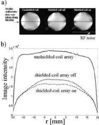
FIG. 5: Phantom image comparison acquired with the MRI PET sys-tem including the shielding and the unshielded cases. a) Delrin and coil only, b) Delrin and coil inserted in the RatCap off-case, and c) Delrin and coil inserted in the RatCap on-case. Comparison of uniformity profiles of the coil array for the unshielded case and the shielded case and the RatCAP turned off.
FIG. 6: Picture of experimental setup showing coil mounted inside theµPET and fitted on a rat head.
FIG. 7: Comparison of rat brain image: a) only coil array, and b) coil array inserted in the PET camera with PET data acquisition system running.
were acquired with the RatCap turned on and off. Unifor-mity profiles were also computed from phantom images for the shielded and unshielded case and shown in Fig. 5.b). The uniformity profiles in Fig. 5.b) demonstrate that the aluminum shielding reduced the SNR of the RF coil array by 66% for both RatCAP operating conditions (SNR (”Unshielded”) = 61.7, SNR (”OFF”) = 51.0, and SNR (”ON”) = 24.0) of the RatCAP. These profiles show an important decrease in the SNR of the coil for the shielded case. However, the unifor-mity maintains a very similar pattern to the unshielded case. Simultaneous ex vivo image acquisition of rat brain were car-ried out with the RatCAP inserted into the bore of the BNL 4T human scanner as shown in Fig. 1a) with the experimental arrangement of Fig. 6. Images of Fig. 7 show that the alu-minium can efficiently shield the RF signals (100 MHz clock) produced by the electronics modules in the miniaturized PET camera (mainly from the 100 MHz clock), which were only 2 cm distant from the MR image isocenter; the weak RF noise component resulting from the PET electronics did not com-promise the quality of the MR images. However, the proxim-ity (2mm) between the aluminium can and the RF coil array reduced the SNR three fold with respect to the unshielded case forcing to average a larger number of experiments for the re-quired contrast to noise. The MR images showed minimum RF noise due the PET electronics despite the close proxim-ity between the PET camera and the MRI RF coil. Similarly,
IV. DISCUSSION
experimental results demonstrate that it is indeed possible to simultaneously acquire reasonable quality PET and MRI im-ages employing the RatCAP and a shielded-saddle coil array. Neither the MRI nor the PET images displayed any artifacts attributable to the melding of the two imaging modalities. These results may pave the way for creation of more com-plex imagers that will permit continued study of this new area of multi-modality, complementary imaging.
Acknowledgement
S. S. is supported by a Ph D stipend from the National Council of Science and Technology of Mexico (CONACyT),
and thanks Laboratory Directed Research and Development from U.S. Department of Energy (OBER). This work was supported by the U.S. Department of Energy (OBER) under Prime Contract No. DE-AC02-98CH10886. Support from In-novamedica is gratefully appreciated.
[1] H. Zaidi, Z. Med. Phys.16, 5 (2006).
[2] H. A. Wolbart, W. R. Hendee, Radiology.238, 16 (2006). [3] S. R. Cherry, Annu. Rev. Biomed. Eng.8, 35 (2006).
[4] N. Volkow, B. Rosen, and L. Farde, Proc. Natl. Acad. Sci. USA.
94, 2787 (1997).
[5] D. W. Townsend, S. R. Cherry, Eur. Radiol.11, 1968 (2001). [6] P. K. Marsden, D. Strul, S. F. Keevil, S. C. Williams, and D.
Cash, Br. J. Radiol.75, S53 (2002).
[7] Y. Shao, S. R. Cherry, K. Farahani, K. Meadors, S. Siegel, R. W. Silverman, and P. K. Marsden, Phys. Med. Biol.42, 1965 (1997). [8] R. B. Slates, K. Farahani, Y. Shao, P. K. Marsden, J. Taylor, P. E. Summers, S. Williams, J. Beech, and S. R. Cherry, Phys. Med. Biol.44, 2015 (1999).
[9] Y. Shao, S. R. Cherry, K. Farahani, R. Slates, R. W. Silverman, K. Meadors, A. Bowery, S. Siegel, P. K. Marsden, and P. B. Garlick, IEEE Trans. Nucl. Med.44, 1167 (1997).
[10] P. Vaska, C. L. Woody, D. J. Schlyer, S. Shokouhi, S. P. Stoll, J. F. Pratte, P. O’Connor, S. S. Junnarkar, S. Rescia, B. Yu, M. Purschke, A. Kandasamay, A. Villanueva, A. Kriplani, V. Radeka, N. Volkow, R. Lecomte, and R. Fontaine, IEEE Trans. Nucl. Sci.51, 2718 (2004).
[11] S. Shokouhi, P. Vaska, D. J. Schlyer, S. P. Stoll, A. Villanueva, A. Kriplani, and C. L. Woody, IEEE Trans. Nucl. Sci.52, 1305 (2005).
[12] R. Slates, S. R. Cherry, A. Boutefnouchet, Y. Shao, M. Dahlbom, and K. Farahani, IEEE Trans. Nucl. Sci. 46, 565 (1999).
[13] F. D. Doty, G. Entzminger, J. Kulkarni, K. Pamarthy, and J. P. Staab, NMR Biomed.20, 304 (2007).
[14] P. Vaska, C. L. Woody, D. J. Schlyer, S. Shokouhi, S. P. Stoll, J. F. Pratte, P. O’Connor, S. S. Junnarkar, S. Rescia, B. Yu, M. Purschke, A. Kandasamay, A. Villanueva, A. Kriplani, V. Radeka, N. Volkow, R. Lecomte, and R. Fontaine, IEEE Trans. Nucl. Sci.51, 2718 (2004).
[15] S. Shokouhi, P. Vaska, D. J. Schlyer, S. P. Stoll, and A. Vil-lanueva, IEEE Trans. Nucl. Sci.52, 1305 (2005).
[16] D. I. Hoult, R. E. Richards, J. Magn. Reson.24, 71 (1976). [17] W. T. Sobol, Rev. Magn. Reson. Med.1, 181 (1986).