Enhancement of Bone Healing
through Mechanical Stimulation
Natacha Rosa
Dissertation submitted to Faculdade de Engenharia da Universidade do Porto
to obtain the degree of
Doctor of Philosophy in Mechanical Engineer
Supervisor:
Professor Dr. António Torres Marques
Co-Supervisors:
Professor Dr. Fernão Domingos de Magalhães
Professor Dr. Ricardo João Ferreira Simões
This thesis is dedicated to mom, sis, dad and Ivo
Acknowledgments
The completion of this thesis could not be possible without the participation and assistance of a number of people whose names may not all be enumerated. However, their support has been crucial along the way and I’m very grateful to each and every person.
I would like to express my gratitude to my supervisor and co-supervisors, Professor Antonio Torres Marques, Professor Fernão Domingos de Magalhães and Professor Ricardo Simões, for their always constructive critique and encouragement, which helped me to conceptualize and accomplish my PhD thesis.
I would like to thank José Dias and Vladimiro Fernandes from Artur Salgado S.A. for providing the intramedullary nails and the respective instrumentation. Their contribution was essential for my work.
I would like to thank Professor Maria Helena, Professor Pedro Gomes, Jóse Carlos and Liliana Grenho from the Laboratory of Bone Metabolism and Regeneration at the Faculty of Dental Medicine of the University of Porto, for helping me with the cytocompatibility evaluation and for allowing me to use their facilities and materials. It was an honor and pleasure to know them, to work and to learn with them.
I would like to thank all my colleagues from the Mechanical Department for guidance and support over the years, both professionally and personally, and for making me fell so welcome. At last, but definitely not least, my sincere gratitude to the constant support, encouragement and unconditional love of my family, boyfriend and friends.
This PhD thesis was funded by the Foundation for Science and Technology (FCT) through the research grand SFRH/BD/87089/2012.
This work was financially supported by projects POCI-01-0145-FEDER-006939 - Laboratory for Process Engineering, Environment, Biotechnology and Energy – LEPABE and NORTE‐01‐0145‐ FEDER‐000005 – LEPABE-2-ECO-INNOVATION, funded by FEDER funds through COMPETE2020 - Programa Operacional Competitividade e Internacionalização (POCI) and Programa Operacional Regional do Norte (NORTE2020), by the project UID/CTM/50025/2013 and by national funds through FCT - Fundação para a Ciência e a Tecnologia.
Publications
Articles:
Rosa, N., Simoes, R., Magalhães F. D. and Marques, A. T., From mechanical stimulus to bone formation: A review. Medical Engineering & Physics, 2015. 37(8): 719-28.
Rosa, N., Marta, M., Vaz, M., Tavares, S., Simoes, R., Magalhães, F. D. and Marques, A.T., The Biomechanical Perspective of the Intramedullary Nailing Evolution. Submitted (2016).
Rosa, N., Marta, M., Vaz, M., Tavares, S., Simoes, R., Magalhães, F. D. and Marques, A.T., The Biomechanical History of Intramedullary Nailing. Submitted (2016).
Rosa, N., Magalhães F. D., Simoes, R. and Marques, A.T., Bone an Outstanding Composite Material. To be submitted (2016).
Rosa, N., Tavares, S., Vaz, M., Tavares, S., Monteiro, J., Tavares, P. J., Carbas, R. J. C., Simoes, R., Magalhães, F. D. and Marques, A.T., Composite Tibia Stiffness concept study: Experimental validation of a finite element model. To be submitted (2017).
Presentations at national and international conferences:
Rosa, N. and Marques, A. T. The effect of cement bone-interface on the behaviour of hip arthroplasty replacement in Materiais2013. 2013. Coimbra, Portugal
Rosa, N. and Marques, A. T. A Perspective on Bone-Cement Interface Loosening in Hip Implants in 5th Portuguese Congress on Biomechanics. 2013. Espinho, Portugal
Rosa, N., Magalhães, F. D., Simoes, R. and Marques, A.T. Enhanced bone healing through mechanical stimulation by implanted piezoelectric actuators in International Joint Conference on Biomedical Engineering Systems and Technology (BIOSTEC). 2014. Angers, France
Rosa, N., Magalhães, F. D., Simoes, R. and Marques, A.T. Intramedullary Nailing Stability in the Bone Healing Process in 1st Doctoral Congress in Engineering. 2015. Porto, Portugal
Rosa, N., Magalhães, F. D., Simoes, R. and Marques, A.T. Nailing Stability during Tibia Fracture Early Healing Process: A Biomechanical Study in International Conference and Expo on Biomechanics and Implant Design. 2015. Florida, USA.
“Take small steps so that you do not fall, bring the best out of you and be driven by a passion to be better”
Abstract
Long bone fractures are one of the most common serious musculoskeletal system injuries, and for which intramedullary nail is the recommended method to enable healing and injured site mobility and function recovery. Despite the high rate of success ensured by this stabilization technique, tibia shaft fractures are still associated with a prolonged healing time. This limitation represents a substantial burden to society and patients. The main goal of this thesis is, by taking advantage of the potentialities given by intramedullary nail fixation method and not interfering with its normal functioning, propose an innovative device which by applying additional well-aimed and well-timed low-magnitude high-frequency interfragmentary mechanical stimulus at the early healing stage will enhance the recovery process quality and progress. The understanding that the mechanical environment at bone fracture site, and more importantly the interfragmentary movements, strongly influence the rate and quality of the callus formation, was complemented with a study of the bone-implant stability concept. Through this analysis a strategy was proposed, considering both finite element analysis and mechanical tests under simple and reproducible conditions, while reflecting physiological load and bone orientation. In this study, a stable bone-implant construct demonstrated that, despit the system’s high stiffness, the interfragmentary site will always be subjected to some motion, and that during early healing phase the nail will support a significant portion of the load applied on the lower limb. Based on the acquired knowledge, and considering the thesis goal, ferrite was chosen as the actuator material. Ferrite’s displacement can be induced by a magnetic field, giving the device an additional advantages over conventional wired actuators, such as higher safety and operating life. The affinity of MG-63 cells for selected ferrite samples was also evaluated, as well as the influence of the removal of the static magnetic field on their adhesion and proliferation. Both ferrite materials tested, 𝑁𝑖0.27𝐶𝑢0.14𝑍𝑛0.6 and Sr-Ca, showed strong evidences of being cytocompatible. Considering the material potential for not being toxic to the human body, it was possible to advance the idea into the development of a demonstration model where the principle of a ferromagnetic actuator coupled to the fixation device and controlled through a magnetic field can be easily perceived. The demonstration model showed that this new approach for enhancing fracture healing was able to reflect clinicians’ needs and at the same time respect the human body’s biological processes. As such, the goal outlined in this thesis was successfully achieved.
Resumo
As fraturas dos ossos longos são umas das lesões mais comuns e graves do sistema músculo-esquelético e cuja cicatrização e recuperação da mobilidade e funcionamento é garantido pela aplicação de cavilhas intramedulares, sendo que, esta é considerada a intervenção preferencial para o efeito. Apesar da elevada taxa de sucesso providenciada por esta técnica de estabilização óssea, as fraturas diafisárias da tíbia continuam associadas a um tempo de recuperação demasiado longo. Esta limitação representa uma sobrecarga consideravel para a sociedade e para os pacientes. Considerando as potencialidades conferidas pelo método de fixação com cavilhas intramedulares e sem interferir com o seu normal funcionamento, o principal objetivo desta tese consistiu em propor um dispositivo inovador que através da aplicação correta de estímulos mecânicos de baixa magnitude e elevada frequência durante a fase de recuperação óssea inicial, seja capaz de melhorar a qualidade e a progressão do processo de recuperação óssea. A compreensão sobre a forte influencia que ambiente mecânico tem na fratura em recuperação, e principalmente os movimentos interfragmentários presentes, têm sobre a velocidade de formação e a qualidade do calo ósseo obtido, foi complementada com um estudo sobre o conceito de estabilidade osso-implante. Através deste estudo foi proposta uma estratégia que considera a análise em elementos finitos assim como ensaios mecânicos em condições simples e reprodutíveis, e refletindo a orientação e aplicação de cargas ósseas fisiológicas. Neste estudo, foi demonstrado a ocorrência de movimentos interfragmentários da fratura perante uma construção osso-implante estável mesmo tratando-se de um sistema rígido. Foi também demosntrado que durante a fase inicial de recuperação óssea é a cavilha intramedular que suporta grande porção da carga aplicada nos membros inferiores. Baseado no conhecimento adquirido e tendo em consideração o objetivo principal da tese, a ferrite foi selecionada como material base para o atuador. O movimento da ferrite pode ser induzido pelo campo magnético, o que garante uma vantagem adicional ao dispositivo quando comparado com os atuadores convencionalmente conectados por fios tanto ao nivel de segurança como em terms de periodo de vida util. A afinidade das células MG-63 para amostras selecionadas de ferrite foram testadas, assim como a influência em relação á adesão e proliferação celular ao ser removido um campo magnético permanente. Tanto as ferrites 𝑁𝑖0.27𝐶𝑢0.14𝑍𝑛0.6 como Sr-Ca testadas, mostraram fortes evidências de serem citocompatíveis. O potencial de não toxicidade do material, permitiu o desenvolvimento de um modelo de demonstração onde o princípio de um atuador ferromagnético acoplado ao dispositivo de fixação e controlado através de um campo magnético foi facilmente percetível. O modelo de demonstração mostrou que a nova solução desenvolvida para melhorar a recuperação da fratura ossea foi capaz de refletir as
necessidades do clínico e, ao mesmo tempo, respeitar o processo biológico do organismo humano. Desta forma, o objetivo delineado nesta tese foi alcançado com sucesso.
xvii
Contents
Acknowledgments ... v Publications ... ix Abstract ... xiii Resumo ... xvList of Figures ... xix
List of Tables ... xxvii
Nomenclature ... xxix CHAPTER 1 ... 1 1. Introduction ... 1 1.1. Motivation ... 1 1.2. Thesis objectives ... 12 1.3. Document structure ... 13 1.4. References ... 15 CHAPTER 2 ... 21 2. Literature review ... 21
2.1. Tibia mechanical functional structure and hierarchical organization ... 21
2.2. From mechanical stimulus to bone formation ... 40
2.3. Fracture and healing ... 65
2.4. Intramedullary nailing biomechanical concept evolution: Understand the past to predict the future ... 74
CHAPTER 3 ... 123
3. Bone-intramedullary nail system stability ... 123
3.1. Material and methods ... 130
3.2. Results ... 150
3.3. Discussion ... 158
3.4. Conclusion ... 167
xviii
CHAPTER 4 ... 175
4. Actuator selection ... 175
4.1. Piezoelectric stacks ... 176
4.2. Electromagnetic vibration actuator ... 199
4.3. References ... 204
CHAPTER 5 ... 209
5. Cytocompatibility evaluation ... 209
5.1. Materials and methods ... 211
5.2. Results ... 222
5.3. Discussion ... 238
5.4. Conclusions ... 244
5.5. References ... 244
CHAPTER 6 ... 249
6. Bone healing enhancement device: Concept demonstration model ... 249
6.1. Materials and methods ... 251
6.2. Results and discussion ... 253
6.3. Conclusion ... 255
6.4. References ... 256
CHAPTER 7 ... 259
7. General conclusion and future work ... 259
CHAPTER 8 ... 261
xix
List of Figures
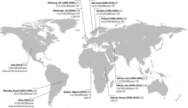
Figure 1.1 - Few worldwide epidemiological studies on the incidence of tibia fractures. TF -Tibia fractures, TSF -Tibia shaft fractures. World map image obtained from [24] and incidence calculated based on total country or city population data from [25, 26] .... 2 Figure 1.2 - Accidental and intentional percentage tibia fractures according to the age groups
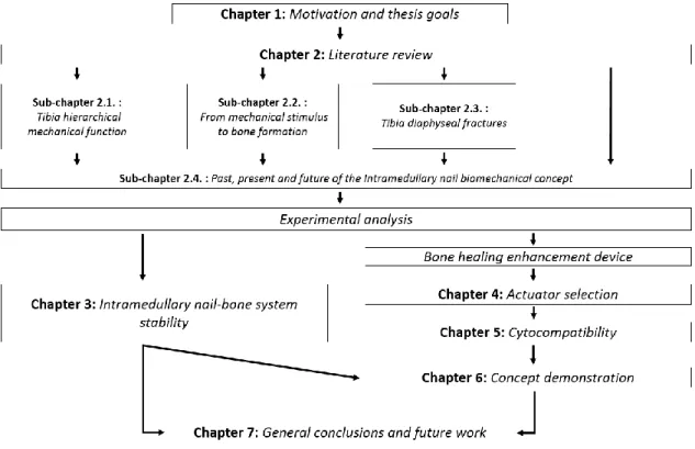
and gender which occurred between the XIX and XX century, based on medical records from Coimbra and Lisbon. Data entirely obtained from [28]. The age groups were defined according to the criteria used by Buikstra and Ubelake [32] ... 3 Figure 1.3 - Overall thesis structure and how its chapters and sections are linked together ... 15 Figure 2.1 - Representation of the tibia positioning in the lower leg (d), with localization of the
main anatomical landmarks from the posterior (b) and anterior view (c) and cross-section images (a) along the tibia showing its shape variation as well as cortical and trabecular bone portions. ... 24 Figure 2.2 - Diagram showing tibia diaphysis bone microscopic hierarchical organization and its
main cellular population. Adapted from [66-71] ... 27 Figure 2.3 - Schematic representation of mechanical loading that causes interstitial fluid flow
through bone’s lacuna-canalicular network (adapted from Duncan et al. [9]). The tension/compression stresses associated with bending cause a pressure gradient that promotes fluid flow along the osteocyte ... 43 Figure 2.4 - Mechanical usage window defined by Frost’s "mechanostat" theory of bone
adaptation to strain (adapted from Duncan et al. [9] and Frost [95]). The horizontal arrow at the bottom shows the typical minimum effective strain (MES) levels and the set point values for the bone’s thresholds and ultimate strength – microstrain (μɛ), stress (MPa) and unit-load (kg/mm2) ... 48 Figure 2.5 - Schematic chronological representation of the turning points in the evolution of the
intramedullary fixation, from the 16th century and up to the 20th century. Information is arranged according to: (a) Timeline, (b) Application sites, (c) Materials used, (d) Biomechanical concept ... 75 Figure 2.6 - Diagram showing Küntscher femoral nail (from two different views) with the clover-leaf cross-section (a) and the longitudinal slot (b) ... 79 Figure 2.7 - Image exemplifying the overall structure of a flexible reamer (a) with the distal drill
bit, a Rush nail (b) with a proximal hook end that prevents rotation and stabilizes the fracture and an Ender’s nail (c) ... 81
xx Figure 3.1 - Diagram showing the physiological orientation of the tibia. Where the orientation planes - coronal (a) and sagittal (b) - and the tibia reference axes: the vertical axis (dark dotted line), the mechanical axis (dark gray continuum line or (c)) and the anatomical axis (light gray continuum line), are represented. A - Medial spine (or medial intercondylar eminence), B - Center of the tibia, C - Knee center, D - Ankle center, E - Lateral spine (or lateral intercondylar eminence) ... 131 Figure 3.2 - SawBones manufacture information [21] and physiological values from literature
[22, 54-56] on cortical bone thickness distribution along the tibia ... 132 Figure 3.3 - Illustration of the segmentation adopted, the theoretical cortical wall-thickness
considered based on literature and the average wall-thickness obtained after appropriate SolidWorks canal-formation tools were applied... 134 Figure 3.4 - A 4-point bending jig at different process stages: (A) 3D SolidWorks version, (B) 3D
printed ABS replicate version and (C) Aluminium alloy AA6082-T6 machined final version ... 136 Figure 3.5 - Image of the torsional test top jig with the 3D printed personalized bone contact zone ... 137 Figure 3.6 - Testing configuration, grips designs and the measurement devices used in the axial
compression assay on the intact composite tibia model: (A) Illustration of the test set-up with detailed information of the jigs from a sagittal section and (B) Image of the test set up ... 138 Figure 3.7 - Testing configuration, grips design and the measurement devices used for the 4-point
bending assay on the intact composite tibia model: (A) Illustration of the test set-up with the tibia on coronal orientation and with a exemplification of the switching mechanism used between the coronal and sagittal loading mode and (B) Image of the test set up for 4-point bending with the tibia sagittal orientation ... 139 Figure 3.8 - Testing configuration used for the shear assay on the intact composite tibia model
with the bone on sagittal orientation: (A) Illustration of the test set-up and (B) Image of the test set-up ... 139 Figure 3.9 - Custom testing configuration and the measurement devices used for the torsional
assay on the intact composite tibia model where: (A) Simplified illustration of the torsional test set-up and (B) Image of the test set-up. The measuring apparatus used to record the system rotation - (a) weight and their support structure fall and (b) laser projected and motion registration – and the (c) thrust ball bearing and (d) graph paper, are also represented ... 140
xxi Figure 3.10 - Schematic representation of the electronic spackle pattern interferometry (ESPI) experimental arrangement system. Image constructed based in information from [69, 70, 74, 75] and the image of the computer was obtained from [76] ... 143 Figure 3.11 - Schematic representation of the digital image correlation (DIC) technique using
virtual extensometers experimental arrangement system where: (A) Light source, (B) CCD digital camera, (C) Speckled composite tibia under 4-point bending loading and (D) speckled surface under analysis. Image constructed based in information from [87] and the image of the computer was obtained from [76] ... 146 Figure 3.12 - Schematic representation of the strategy used for the calculation of the horizontal
and vertical gauges displacements variations during torsional assays ... 147 Figure 3.13 - ESPI analysis on the tibia midsection site displacement from the whole bone
structure axial compression at (A) 20 and (B) 80 N. The results are presented as a (a) three-dimensional displacement map, (b) two-dimensional displacement map and the (c) displacement along the x-axis at position y = 24.6 μm ... 152 Figure 3.14 - Cross-section of the tibia-intramedullary nail finite element model displacement
distribution in yy direction (mm) during 4-point bending load in the sagittal plane and in response to 20 Nm bending moment ... 153 Figure 3.15 - Comparison of the bone fragments (upper and lower portion) and intramedullary
nail deformation from finite element simulation (FE) at the (A) axial and (B) anteroposterior direction and in response to 150 N axial compression loading of the osteotomized composite tibia fixed with the intramedullary nail system ... 155 Figure 3.16 - Bone fragments (upper and lower portion) and intramedullary nail rotation registers
from finite element simulation (grey) and mechanical experimentation DIC-measurements (diagonal stripes) in response to 5 Nm torsional loading of the osteotomized composite tibia fixed with the whole intramedullary nail system. FE - Finite element simulation, ME - Mechanical experimentation DIC measurements 155 Figure 3.17 - Bone fragments (upper and lower portion) and intramedullary nail deflection
registers from finite element simulation (grey) and mechanical experimentation DIC-measurements (diagonal stripes) as a response to 20 Nm N 4-point bending loading in the (A) sagittal and (B) coronal plane of the whole osteotomized composite tibia fixed with the intramedullary nail system. FE - Finite element simulation, ME - Mechanical experimentation DIC measurements ... 156 Figure 3.18 - Bone fragments (upper and lower portion) and intramedullary nail deflection
registers from finite element simulation (FE) and mechanical experimentation DIC-measurements (ME) as a response to 100 N shear loading in the (A) sagittal and (B)
xxii coronal plane of the whole osteotomized composite tibia fixed with the intramedullary nail system ... 157 Figure 4.1 - Schematic cross-sectional representation of a multilayer PZT piezo-stack with
longitudinal expansion, built up from individually contacted piezoceramic discs. Based on [9, 16, 18, 24]. ... 181 Figure 4.2 - Schematic representation from the anterior and lateral perspective of the set-up
system based on a piezo stack (C) which was placed on a solid base and was mounted into a mechanical press (D) with known load (E), moving the attached mechanics (D) by electrical voltage stimulation. The strain of the stack is measured with the use of a laser Doppler vibrometer optical sensor head (A) which laser beam direction is controlled by mirror system (B) ... 189 Figure 4.3 - Actuator finite element model simulation during intramedullary nail hammering
where (A) is the normal stress distribution at the piezo-stack surface in direction X (direction of the piezoelectric effect), (B) in the normal strain distribution in direction X and (C) is the normal shear strain distribution in the YZ plane ... 191 Figure 4.4 - Actuator finite element model simulation during intramedullary nail removal where
(A) is the normal stress distribution at the piezo-stack surface in direction X (direction of the piezoelectric effect), (B) in the normal strain distribution in direction X and (C) is the normal shear strain distribution in the YZ plane ... 192 Figure 4.5 - Schematic voltage/stroke diagram for the model Pst 150/2x3/5 stack actuator under
different loads ... 193 Figure 4.6 - Schematic voltage/stroke diagram for the model Pst 150/2x3/7 stack actuator under
different loads ... 193 Figure 4.7 - Finite element analysis concept used for the understanding of the relation between
the actuator force application and the generated interfragmentary site motion. The 150 N actuator force case was used for exemplification ... 195 Figure 4.8 - Examples of different ferrite sizes and shapes ... 204 Figure 5.1 - Chart showing the overall structural organization of the experiments and the
associated evaluation methods ... 211 Figure 5.2 - The test materials considered in the study: (A) Zn irregular shaped ferrite sample and
(B) Sr-Ca ferrite sample showed from different views ... 212 Figure 5.3 - Resazurin assay: non reduced blue resazurin compound is present in the wells with
xxiii Figure 5.4 - Day 4 CAM assay protocol overview were: (A) albumin removal, (B) CAM dissociation from the egg shell membrane, (C) isotonic solution injection and (D) the square window creation for blood vessels development monitoring, are represented ... 219 Figure 5.5 - MTT measurements of MG-63 cells cultured on Zn irregular ferrite samples after 1
and 3 days. The values are the mean ± SD and expressed as percentage of positive controls (cell seeding density of 5 X 10⁴ cell/ml) ... 223 Figure 5.6 - Ferrite surface topographies after 3-day culture with MG-63 cells obtained from
optical microscopy: (A and C) Cell adhesion and proliferation on ferrite samples and (B and D) Negative control samples which were not exposed to cells. Images magnification of 0.7X and 2X was used in the top and bottom images, respectively. Note the purple precipitates present on the seeded samples (A and C), compared to the non-seeded samples (B and D) (cell seeding density of 5 X 10⁴ cell/ml) ... 224 Figure 5.7 - SEM image of Zn ferrite non-fractured surface. Images were obtained from secondary
electrons. Image magnification of 2500X ... 224 Figure 5.8 - X-ray spectrum of the Zn ferrite. The horizontal axis is the energy scale and the
vertical axis is the number of photons per energy interval. The x-ray identification, element, is indicated in the vicinity of the peaks ... 225 Figure 5.9 - Average measurement of static contact angle on Zn ferrite surface. The image
represents a 103.5° contact angle ... 226 Figure 5.10 - Photographs of CAM (A) through in ovo analysis immediately after ferrite sample
deposition and (B) after 11 days of incubation through ex ovo analysis. The arrow indicates the presence of new blood vessels sprouting towards the ferrite sample 227 Figure 5.11 - Average number of CAM total blood vessels of type I (grey with diagonal stripes), II
(diagonal stripes) and III (dark grey with diagonal stripes) and convergence blood vessels of type I (grey), II (white) and III (dark grey) on CAM images at day 0 and 3 from Zn ferrite sample deposition ... 227 Figure 5.12 - Average blood vessels diameter of type I (dark grey), II (diagonal stripes) and III
(grey) calculated from CAM images recorded at 0 and 72 hours after Zn ferrite sample deposition ... 228 Figure 5.13 - MTT counts on MG-63 cells cultured on Zn (in grey) and Sr-Ca (diagonal stripes)
ferrite samples, 1 and 3 days. The MTT counts are presented as the mean ± standard deviation and expressed as percentage of positive controls (cell seeding density of 5 X 10⁴ cell/ml) ... 229 Figure 5.14 - Resazurin measurements at 1, 3, 7 and 11 days of MG-63 cells cultured on Sr-Ca
xxiv an oxygen environment (dark grey - Tc+O2), Curie temperature under nitrogen environment (diagonal stripes - Tc+N2) and strong external magnetic field with opposite polarity (light grey - E). The resazurin counts are presented as the mean ± standard deviation and expressed as percentage of control (cell seeding density of 2 X 10⁴ MG-63 cell/ml). The results obtained from resazurin measurements on permanent magnetic samples were used as control. (* - Significantly different from control; ** - Significantly different from Tc+N2) ... 230 Figure 5.15 - Resazurin counts at 1, 3, 7 and 11 days of MG-63 cells cultured on Curie temperature
and under nitrogen environment demagnetized Sr-Ca ferrite samples with additional mechanical cleaning (denoted as “MC”) and without the mechanical cleaning (denoted as “No MC”). The resazurin counts are presented as the mean ± standard deviation and expressed as percentage of controls (cell seeding density of 2 X 10⁴ MG-63 cell/ml). The results obtained from resazurin measurements on permanent magnetic samples were used as control. (* - Significantly different from “No MC”) ... 231 Figure 5.16 - X-ray spectrum of the Sr-Ca ferrite. The horizontal axis is the energy scale and the
vertical axis is the number of photons per energy interval. The x-ray identification, element, is indicated in the vicinity of the peaks ... 232 Figure 5.17 - Average measurement of static contact angle on Sr-Ca ferrite surface. The image is
a representation of a 68.4° contact angle ... 233 Figure 5.18 - SEM photographs from 1 day incubation of MG-63 cells cultured on Sr-Ca ferrite
demagnetized surface through (A,B) strong external magnetic field of opposite polarity and (C,D) Curie temperature and under an oxygen atmosphere. Images were obtained from secondary electrons. Two magnifications are shown: 2500X (A,C) and 5000X (B,D) ... 234 Figure 5.19 - SEM photographs from 1 day incubation of MG-63 cells cultured on Sr-Ca ferrite
demagnetized surface through Curie temperature and under a nitrogen atmosphere and subjected to abrasive mechanical cleaning. Images were obtained from secondary electrons. Two magnifications are showed: 2500X (A) and 5000X (B) ... 235 Figure 5.20 -Profilometry 3D images of the Sr-Ca ferrite surfaces as determined from microscope-based white light interferometry and where the influence of the de-magnetization process and the absence of it, was evaluated: (A) magnetic, (B) de-magnetized through the application of a strong electric field, (C) de-magnetized with Curie temperature in an oxygen atmosphere, and (D) ferrite de-magnetized with Curie
xxv temperature in a nitrogen atmosphere. Images magnification of 0.25X was used for (A) and 0.5X was used for (B), (C) and (D) samples ... 235 Figure 5.21 - Surface topographies of the Sr-Ca ferrite surfaces as determined from microscope-based white light interferometry and where the influence of the abrasion mechanical cleaning was evaluated: (A) demagnetized Sr-Ca ferrite through Curie temperature in a nitrogen atmosphere and not subjected to hard mechanically cleaned surface and (B) the same material however subjected to abrasive mechanical cleaning. Images magnification of 0.5X was used ... 237 Figure 6.1 - Schematic representation of the proposed magnet actuator device linked to an
intramedullary nail for bone healing enhancement. The implanted actuator is externally activated and controlled by a handheld emitting device which electrical current is obtained from a frequency generator amplified signal. Tibia with fibula and intramedullary nail image obtained from [9] and fracture image obtained from [10] ... 250 Figure 6.2 - Block diagram of the general constative components in the concept demonstration
models ... 251 Figure 6.3 - Schematic representation of the (C) concept model developed for 'proof of concept'
demonstration purpose and the set-up system used for the frequency measurements based in the model 2. The system electronical apparatus comprises: (A) laser Doppler vibrometer optical sensor head, (B) oscilloscope, (D) amplifier, (E) laser Doppler vibrometer controller and (F) laser Doppler vibrometer signal analyser unit ... 252 Figure 8.1 - Photographic registers from the intramedullary nail implantation process ... 261 Figure 8.2 - X-ray from the tibia composite with the intramedullary nail implanted from the (A)
xxvii
List of Tables
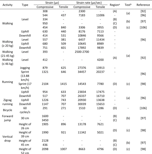
Table 2.1 - Peak tibiofemoral joint compressive forces during several daily activities and expressed as times the body weight ... 25 Table 2.2 - In vivo humans bone strain values measured during different types of physical
activities, reported in the literature ... 49 Table 2.3 - AO classification of diaphyseal long bones fractures. The fracture type could be A:
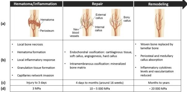
Simple fractures without a third fragment; A1: spiral, A2: oblique (≥30°), A3: transverse (<30°); B: Wedge fractures with a third or more fragments, but with contact between the fragments; B1: spiral wedge, B2: bending wedge, B3: fragment wedge; C: Complex fractures; C1: spiral, C2: segment, C3: irregular. The fracture group could be 1: Fractures in torsion; 2: Fracture in bending or 3: Fracture due to other mechanisms. Adapted from [3, 14, 16] ... 67 Table 2.4 - Schematic representation of the three-stage model for secondary bone healing. The
information is arranged according to: (a) visual representation, (b) general description of the main events that characterize each stage, (c) duration of each stage and (d) stiffens alteration with the increase in the Young’s modulus. Adapted from: [20, 31-33]... 71 Table 2.5 - Selected mechanical properties of different types of intramedullary nailing materials
in comparison with the cortical bone. UTS – Ultimate tensile strength, TYS – Tensile yield strength ... 95 Table 3.1 - Review on in vitro mechanical experimentation (ME) and/or finite element analysis
(FE) of tibia bone with or without an intramedullary nail implanted. M – Medium size, L - Large size, S – Sagittal plane, C - Coronal plane, IR - Internal rotation, ER - External rotation, AT - Anterior surface in tension, PT - Posterior surface in tension, LT - Lateral surface in tension, NIA – No information available ... 126 Table 3.2 - Comparison between the 4th generation composite intact tibia mechanical
experimentation (ME) and finite element simulation (FE) with published experimental data from the study developed by Anneliese Heiner [20] where the same tibia model was considered. NIA – No information available ... 151 Table 3.3 - Stiffness (mean value ± SD) of the composite tibia-intramedullary nail based on
mechanical experimentation with data from the machine system and DIC measurement method and from the finite element (FE) simulation and their comparison to published data from the study developed by Penzkofer et al. [11]. SS - stainless steel, TA - titanium alloy, UNCOMP - uncompressed bone-intramedullary nail
xxviii construct system and COMP - compressed bone-intramedullary nail construct system ... 153 Table 4.1 - Average interfragmentary displacement (μm) for each actuator force applied (N) 194 Table 4.2 - Permanente magnets types and typical properties. Data obtained from: [3, 66, 72-76] ... 201 Table 5.1 - Scoring scheme for irritation testing with hen’s egg chorioallantoic membrane ... 226 Table 5.2 - Surface roughness parameters measured in two directions (x and y) of the rougher
magnetic and demagnetized ferrite samples through different methods (strong electric field (E), Curie temperature in an oxygen atmosphere (Tc+ O2) and Curie temperature in a nitrogen atmosphere (Tc+ N2). Data is shown as arithmetic means± standard deviation (±SD) and expressed in µm. 𝑅𝑎: average surface roughness, 𝑅𝑞: root mean square roughness, 𝑅𝑧: mean peak-to-valley roughness ... 236 Table 5.3 - Surface roughness parameters measured in two directions (x and y) of the
demagnetized Sr-Ca ferrite through Curie temperature in a nitrogen atmosphere (Tc + N2) and the ferrite material in the same conditions however subjected to additonal mechanical cleaning (+ MC) surface treatment. Data is shown as arithmetic means± standard deviation (±SD) and expressed in µm. 𝑅𝑎: average surface roughness, 𝑅𝑞: root mean square roughness,𝑅𝑧: mean peak-to-valley roughness ... 237 Table 8.1 - Properties of some different types of actuators. The two test samples are highlighted
in dark grey ... 263 Table 8.2 - Few parameters adopted in the studies where sheep was used for the evaluation of
xxix
Nomenclature
Abbreviations/acronyms
3D Three-dimension
ABS Acrylonitrile butadiene styrene
AC Alternating current
AISI American Iron and Steel Institute
AO Arbeitsge-meinschaft für Osteosynthesefragen (meaning Association for Osteosynthesis)
ASIF Association for the Study of Internal Fixation ASLS Angular stable locking system
ASTM American Society for Testing and Materials
AT Anterior surface in tension
ATP Adenosine triphosphate
BMU Basic multicellular units
BSE Back-scattered electrons
BW Body weight
CAD Computer-aided design
CAGR Compound annual growth rate
CAM Chorioallantoic membrane
CCD Charged coupled device
CENFIM Centro de Formação Profissional da Indústria Metalúrgica e Metalomecânica (meaning Vocational Training Centre of the Metal Industry)
DIC Digital image correlation
CNC Computer numerically controlled
COMP Compressed bone-intramedullary nail construct system
CT Computed tomography
DGAV Direcção-Geral de Alimentação e Veterinária (meaning Portuguese National Authority for Animal Health)
DMSO Dimethyl sulphoxide
E Electrical field
EDS Energy-dispersive X-ray spectroscopy EDTA Ethylenediaminetetraacetic acid
xxx ENaC Epithelial sodium channels
ER External rotation
ESIN Elastic stable intramedullary nailing ESPI Electronic speckle pattern interferometry FAST Flexible axial stimulation
FBS Foetal bovine serum
FCT Foundation for Science and Technology
FDM Fused deposition modelling
FE Finite element
FEPA Federation of European Producers of Abrasives FIN Flexible intramedullary nailing
GmbH Gesellschaft mit beschränkter Haftung (mening company with limited liability)
HET Hen’s egg test
HET-CAM Hen’s egg test - Chorioallantoic membrane
ICCVAM Interagency Coordinating Committee on the Validation of Alternative Methods
IPC/I3N Institute of Nanostructures, Nanomodelling and Nanofabrication INEGI Instituto de Ciência e Inovação em Engenharia Mecânica e Engenharia
Industrial (meaning Institute of Science and Innovation in Mechanical and Industrial Engineering)
IR Internal rotation
IS Irritation score
ISO International Organization for Standardization
LAETA Associated Laboratory for Energy, Transports and Aeronautics
LC Lacuno-canalicular
LEPABE Laboratory for Process Engineering, Environment, Biotechnology and Energy
LET Laboratório de Ensaios Tecnológicos (meaning Technological Testing Laboratory)
LOME Laboratório de Optica e Mecânica Experimental (meaning Laboratory of Optics and Experimental Mechanics)
LT Lateral surface in tension
LVM Low carbon Vacumm melt Molybdenum
xxxi
ME Mechanical experimentation
MEM Minimum essential medium
MES Minimal effective strain
MMPA Magnetic Materials Producers Association
MRI Magnetic resonance imaging
MTT 3-(4,5-dimethylthiazol-2-yl)-2,5-diphenyltetrazolium bromide NADP Nicotinamide adenine dinucleotide phosphate
NIA No information available
NO Nitric oxide
NSAID Nonsteroidal anti-inflammatory drugs
OD Outer diameter
OPG Osteoprotegerin
PBS Phosphate buffer saline
PGE2 Prostaglandin E2
PLLA Poly(L-lactide) acid
PMMA Poly(methyl methacrylate)
PT Posterior surface in tension
PVDF Polyvinylidene fluoride
PZT Lead zirconate titanate
RANKL Receptor activator of nuclear factor-kappaB ligand
RIA Reamer/Irrigator/Aspirator
SAW Surface acoustic wave
SD Standard deviation
SEM Scanning electron microscopy
SIGN Surgical Implant Generation network
SS Stainless steel
TA Titanium alloy
TF Tibia fractures
TSF Tibia shaft fractures
TYS Tensile yield strength
UK United Kingdom
UNCOMP Uncompressed bone-intramedullary nail construct system
UPTEC Parque de Ciência e Tecnologia da Universidade do Porto (meaning Science and Technology Park of University of Porto)
xxxii
UTS Ultimate tensile strength
WCIF Wright cell imaging facility
Chemical nomenclature
𝐴𝑙 Aluminum 𝐴𝑙2𝑂3 Aluminum oxide 𝐴𝑢 Gold 𝐵𝑎 Barium 𝐵𝑎𝑇𝑖𝑂3 Barium titanate 𝐶 Carbon 𝐶𝑎 Calcium 𝐶𝑎𝐶𝑂3 Calcium carbonate 𝐶𝑎10(𝑃𝑂4)6(𝑂𝐻)2 Hydroxyapatite 𝐶𝑜 Cobalt 𝐶𝑂2 Carbon dioxide 𝐶𝑟 Chromium 𝐶𝑢 Copper 𝐹𝑒 Iron 𝐹𝑒2𝑂3 Ferric oxide 𝐹𝑒3𝑂4 Magnetite 𝑀𝑔𝐴𝑙2𝑂4 Magnesium aluminate 𝑀𝑛 Manganese 𝑀𝑛3𝐴𝑙2𝑆𝑖3𝑂12 Spessartine 𝑀𝑜 Molybdenum 𝑁𝑎𝐶𝑙 Sodium chloride 𝑁𝑎𝑂𝐻 Sodium hydroxide 𝑁𝑏 Niobium 𝑁𝑑2𝐹𝑒14𝐵 Neodymium-iron-boron 𝑁𝑖 Nickel 𝑁𝑖𝑇𝑖 Nitinol 𝑂 Oxygen 𝑂2 Oxygen gas 𝑃 Phosphorus 𝑃𝑏 Leadxxxiii 𝑃𝑏(𝑍𝑟1−𝑥𝑇𝑖𝑥)𝑂3 Lead zirconate titanate (or PZT) general molecular formula
𝑃𝑑 Palladium 𝑆 Sulfur 𝑆𝑖 Silicon 𝑆𝑟 Strontium 𝑆𝑟𝐹𝑒12𝑂19 Strontium hexaferrite 𝑆𝑟𝐶𝑂3 Strontium carbonate 𝑇𝑖 Titanium 𝑇𝑖𝑂2 Titanium dioxide 𝑉 Vanadium 𝑍𝑛 Zinc
Symbols
∆𝐿 Change in length 𝛥𝑥 Horizontal displacement 𝛥𝑦 Vertical displacement 𝜆 Wavelength 𝛽 Rotation angle𝐵𝐻𝑚𝑎𝑥 Maximum value of energy product
𝐵𝑟 Flux density
𝐵𝑠 Saturation flux density
𝐶 Distance between the inner and outer support or Capacitance
𝑑𝑖𝑗 Piezoelectric coefficient
𝐸 Electrical field strength or Young Modulus
𝜀 Strain
𝐹 Force
𝑓 Frequency
𝐻 Magnetic field
𝐻𝑐 Coercive field
𝐼 Momento of inertia or electrical current
𝐿 Original length
xxxiv 𝑟 Intramedullary nail mean radius with respect to the closed structure
𝑅𝑎 Average surface roughness
𝑅𝑞 Root mean square roughness
𝑅𝑧 Mean peak-to-valley roughness
𝛿 Data given by the DIC method
𝑆 Slope of the tangent of the initial straight portions of the load-deflection curve
𝑠𝑒𝑐𝐶 Coagulation reaction starting time 𝑠𝑒𝑐𝐻 Hemorrhage reaction starting time 𝑠𝑒𝑐𝐿 Vascular lyses reaction starting time
𝑆𝑖𝑗 Actuator strain
𝑠33𝐸 Compliance
𝑡 Intramedullary nailwall thickness or Time
𝑇𝑐 Curie temperature 𝑡𝑖 Initial position 𝑡𝑓 Final position 𝑢𝑖 Initial permeability 𝑢𝑚𝑎𝑥 Maximum permeability 𝑉 Voltage 𝑉𝑝−𝑝 Peak-to-peak voltage
1
CHAPTER 1
“Engineering is about going in and designing” Lisa Ferrara1. Introduction
This PhD thesis was funded by the Foundation for Science and Technology (FCT) through the research grand SFRH/BD/87089/2012. The thesis was developed in the framework of the Doctoral Program in Mechanical Engineering in association with the Associated Laboratory for Energy, Transports and Aeronautics (LAETA), Laboratory for Process Engineering, Environment, Biotechnology and Energy (LEPABE) and the Institute of Nanostructures, Nanomodelling and Nanofabrication (IPC/I3N) as part of the development of an actuator for bone healing enhancement. The experimental research was conducted at the Faculty of Engineering of the University of Porto, with the collaboration of the Laboratory for Bone Metabolism and Regeneration at the Faculty of Dental Medicine of the University of Porto and Artur Salgado S.A. All the biocompatibility experiments were developed at the Laboratory for Bone Metabolism and Regeneration. The intramedullary nail used during the research study and all the implantation devices required were provided by Artur Salgado S.A.
1.1. Motivation
1.1.1. Tibia shaft fractures: An underestimated problem
Tibial shaft fractures are the most common long bone injuries [1-3]. Most fractures occur between the mid-shaft region and the distal third of the tibia, where the smallest cross-section and moment of inertia are present [3-6]. The tibia shaft fractures are also considered a very painful injury, as demonstrated in a study developed by Kane et al. [7] where this type of fractures attained the highest pain rankings.
The epidemiology of the tibial diaphysis fractures was evaluated in a few studies [8-18]. The incidence was reported based on its variation over the years and between different countries and cities, as presented in Figure 1.1. Although, as stated by Larsen et al. [9], most epidemiological studies are conducted without a geographically well-defined and complete population and the data obtained cannot be extrapolated to a nationwide scale, few representative insights on this fractures type were still considered.
Introduction
2 A common characteristic reported in most studies is the tibial shaft fractures incidence with respect to age and gender. There are two main tibial shaft fractures peaks distributions: the first in young males and the second in older women. In men, the pattern is generally characterized by a high peak at younger age - between 10 to 34 years - which gradually falls until about 60 years, when it then rises again. The female incidence rate, however, reached its lowest values at younger ages, between 20 to 39 years, then increases after menopause, which occurs around 45 years. The rate obtained in older men is normally lower than older female peak. However, in general, the number of fractures affecting men are considered to be at least twice than that affecting women. High tibial fractures registered in men are normally associated as being caused by sport injuries (e.g. soccer and skiing) or traffic accidents. In older women, the low bone mass and high prevalence osteoporosis, which characteristically increases with aging, may greatly influence the tibial peak fracture incidence. In elderly, tibia shaft fractures lead to acute inpatient stay, post-acute patient stay and home healthcare as well as outpatient visits and physical and occupational therapy. Also such fractures in this age group are starting to be associated with high mortality rates, which values have demonstrated to be as high as the ones obtained in hip fractures [12, 16, 19-23].
Figure 1.1 - Few worldwide epidemiological studies on the incidence of tibia fractures. TF -Tibia fractures, TSF -Tibia shaft fractures. World map image obtained from [24] and incidence calculated based on total country or city population data from [25, 26]
In Portugal, there is a lack on nationwide level published data concerning tibia diaphyseal fractures epidemiology characterization, where validated fracture classification, trauma mechanism, length of hospital stay and treatment adopted, are reported. This limitation may be due to the difficulty in obtaining complete statistical detailed country information [19]. Such
Introduction
3 knowledge would help to understand the current state of the nation and its evolutional behavior in the last decades. This would allow for the development of prevention and treatment strategies [10, 14]. However, based on few unpublished references [27] and available literature [28-31], some generalizations were made. Similarly to what is verified worldwide, and as stated during a Portuguese AoTrauma Course [27], in Portugal tibia fractures are also considered as the most common among long bones and are associated with a high rate of open injuries which are considered the more severe cases. The results obtained in a study developed by Mário Peneda [28], “blamed” falls and also road-traffic accidents as the two main causes for lower limb injuries. Based on this study, it was also possible to present a preliminary insight on the country’s gender and age group related tibial fractures incidence (see Figure 1.2). There seem to be a general high predominance (minimum 3-fold) of tibia fractures among men when compared to women. The higher male values are among young and middle-aged adults. The causal factors of such gap are unknown. In women, there is a trend in increase tibial fractures beginning in middle age. According to data from the Portuguese National Health Service [30, 31], the stabilization of this injuries with intramedullary nail fixation method through open fracture reduction, is the sixth most frequent muscular-skeletal chirurgical procedure developed at operating grooms across the country. The number of intramedullary nailing implantations records showed an increase in 324 more cases in 2013 from the 4031 registered in 2009.
Figure 1.2 - Accidental and intentional percentage tibia fractures according to the age groups and gender which occurred between the XIX and XX century, based on medical records from Coimbra and Lisbon. Data entirely obtained from [28]. The age groups were defined according to the criteria used by Buikstra and Ubelake [32]
In comparison with other long bones, tibia fractures are the ones in which healing is most problematic not only due to the demanding mechanical requirements placed upon this bone
Introduction
4 during normal daily activities, but most importantly as a result of the tibiae’s reduce amount of soft tissue [3-6, 33]. Tibia shaft fractures are also more commonly associated with severe trauma due to traffic accident. Such type of impact normally leads to high-energy injuries such as open fractures. The high rate of severe trauma cases may be a consequence of tibial shaft soft tissue reduced protection where its asymmetric positioning leaves the anteromedial surface more vulnerable. In most studies, males are associated with a greater frequency of high-energy trauma which peak incidence is among individuals between 10 to 40 years old. In general, the high-energy trauma frequency among women is low throughout life. Tibia open shaft fractures are particularly difficult to manage and are associated with complications such as wound infection [34] and problems with bone healing. Infections associated with fracture-fixation devices in tibia are generally lower in close fractures, between 0.9 to 4.45% [35]. However, it may rise up to 33% [36] in open fracture cases. The more common problems with bone healing are delayed unions (defined as fractures that have not achieved union at 4.9 months post-fracture) or in more severe cases non-unions (defined as fractures that have not achieved union within 6 to 9 months post-fracture). These undesirable results extend the patient disability and lead to substantial pain. Nevertheless, such disproportionate healing period can occur in any fracture site with higher probabilities in open fractures. Delayed unions and non-union cases, where high-energy trauma is not present, are normally associated to excessive interfragmentary movement, avascularity of fragments, infection or a combination of all those variables. Hence, the type of stabilization method adopted influences the healing rate. Although a profound understanding of the factor contributing for healing failure is lacking, variables like age, gender, hormonal effects, bone necrosis and percent pre-reduction displacement may have a significant impact [1, 3-6, 9, 12, 17, 21, 37-41].
1.1.2. Intramedullary nail: A good stabilization method with space for improvement
1i) Range of application and biomechanical principle
For the vast majority of tibial shaft fractures in adults, interlocking reamed intramedullary nails has become the standard care procedure [42, 43]. The current widespread indication for the use of interlocking intramedullary nailing includes: (a) the management of closed fractures with the exception of proximal and distal fractures of the tibia that are contraindicated due to special positions [44], (b) acute closed fractures [45], (c) open fractures [46, 47] and (d) serious and
1The presentation of the concept behind the thesis motivation: Rosa, N., Simoes, R., Magalhães, F. D.,
Marques, A. T. Enhanced bone healing through mechanical stimulation by implanted piezoelectric actuators, in International joint Conference on Biomedical Engineering Systems and Technology (BIOSTEC), 2014. Angers, France. These conference presentation received the “Best PhD Project Award”.
Introduction
5 complicated fractures. The latter indication cases includes: segmental fractures, polytraumatized patients and additional ipsilateral fractures, morbid obesity [48], failed non-operative treatment of tibial shaft fractures, late management of open tibial fractures, when the definitive care is implemented after the damage control orthopedics concept in polytraumatized patient (i.e. conversion of an external fixator or internal fixator to an intramedullary nailing) [44, 46] and also in pathological fractures (e.g. fracture caused by bone metastatic) [44]. From a biological and mechanical perspective, intramedullary nailing offers several advantage when compared to other stabilization procedures (e.g. cast, external fixator and internal fixator). This procedure is considered to require a minimal surgical approach for its implantation. Also, indirect fracture reduction with reduce disturbance to the fracture site is sometimes possible. This fixation method preserves the periosteal blood supply and even when the reaming technique is adopted (removal of circumferential layers from the bone endosteal surface resulting in the elimination of bone irregularities and enlargement of the medullary canal diameter) the endosteal vasculature is re-established. The central positioning of the intramedullary nail allows it to function as a load-sharing device. During the early healing stage when the fracture site is instable, the nail supports most of the weight applied on the limb. The stress will gradually be transferred to the interfragmentary site with the progressive stiffening of the local tissues (from granulation tissue to cartilage-like and finally calcified callus) [39]. Another interesting characteristic of this stabilization method is that the surgical procedure duration for intramedullary nail implantation is lower than the amount of time required for internal fixation application [27, 49], with average procedure period of 1.9 hours [35]. According to the marked research report [50], internal fixators already form the largest segment of the orthopedic trauma fixation devices market and they are also associated with a trend in future demand increase, where a 6.8% compound annual growth rate (CAGR, calculated as geometric average of annual growth rates [51]) from 2014-2020, is predicted.
ii) Slow healing time
The intramedullary nail fixation technique is considered an effective stabilization method and its good reputation is due to its high rate of successful healing cases. However, tibia shaft fractures stabilized with intramedullary nail may still be associated with a prolonged healing time [12]. As showed in the study developed by Ouyang et al. [44], where an extended evaluation (follow-up period around 26.2 months) on the patients’ average healing time based on a wide range of interlocking intramedullary nails designs in isolated long bone fractures (e.g. tibia, femur and humeral) was taken in consideration, the mean time for tibia fracture union was 5.2 months. Besides the prolonged recovery time, patients that undergo a surgical procedure -
Introduction
6 such as intramedullary nail implantation - require a longer hospital stay as demonstrated in the study developed by Weiss et al. [21], where tibia shaft fractures average hospitalization healing period was 4 (± 9) days. Larsen et al. [9], reported the inpatient duration with average values of 9.4 (± 9.7) days. A higher average hospital stay for the management of tibial diaphyseal fractures with intramedullary nail was stated by Downing et al. [35] as 12.1 days. The management of tibial diaphyseal fractures has always held a particular interest for orthopedic surgeons due to the challenge they represent and the healing process duration is an important parameter with significant burden to the health system and direct implications on the patient’s physical and emotional wellbeing.
The reduce nationwide understanding of the epidemiology and costs to society and healthcare system associated with tibial shaft fractures treated with intramedullary nail, limits the conclusions drawn on the subject. However, it is of general belief that the tibia shaft fractures slow healing process presents a substantial burden to society and patients. The management and recovery process of tibia shaft fractures is often complex and challenging in financial terms not only to the healthcare system, but also in human aspects and facility requirements, since such procedure requires experienced orthopedic surgeons, qualified support staff, expensive equipment and a good rehabilitation strategy (e.g. physiotherapy, medication and follow-up physicians visits) [15]. There is also the social economic burden associated with tibia shaft fractures due to the labor hours lost since the younger generation are the prime victims of this type of injury [23, 52]. The weeks off work comprises the incident occurrence and management time and also the recovery time required until patients can return to their normal routine. According to Downing et al. [35] the recovery process may require an average of 15 weeks off work which may also include around 6.1 outpatients appointments. According to a recent study developed by Antonova et al. [12], in the United States around 500 000 tibia and fibula fractures occur each year which result in 77 000 hospitalizations and account for 569 000 hospital days. Although, it may not be up-to-date, a study presented by Downing et al. [35], gives an insight on tibia shaft fractures cost in the UK and Heckman and Sarasohn-Kahn [41] estimate the cost in the USA. The first study pointed-out a mean hospital cost when intramedullary nailing stabilization method is used of £2226 (around 3183.2€ in 1997 [53]) per patient, with a total cost to society of £6592 (around 9426.6€ in 1997 [53]) per patient when the patient mean time off work is also considered. In the second study, the costs considered were only for tibial shaft fracture management with general operative treatment and no specific stabilization procedure considered. The costs for both surgery and recovery phase were estimated as $20575 (around 17756.2€ in 1997 [53]) per patient and the outpatient rehabilitation process solely would be
Introduction
7 $4317 (around 3725.6€ in 1997 [53]) per case. It is important to highlight that although more closely associated with high-energy open fractures, delay and non-unions cases further worsen the burden of tibia shaft fractures. Tibia shaft fracture also affect patient’s psychological and physical quality of life [12, 54]. The high amount of medication (e.g. strong opioids, NSAID’s, benzodiazepines and injectable corticoids) used by tibia shaft fractures patients during the healing process is a pertinent detail highlighted by Antonova et al. [12]. Besides the burden this may represent for patients, according to Heckman and Sarasohn-Kahn [41] the medication taken during fracture management and the follow-up period could average around $2000 (around 1726€ in 1997 [53]) per case. Hence, tibia shaft fracture healing time represent a considerable economic burden to worldwide society but also to patient’s well-being [12, 21, 37]. Although, no decision should be made solely from an economic basis, more than ever there is an awareness of expenditure in the health service, the concern in cost reduction [35]. The burden associated with tibia shaft fractures is expected to increase with the tendency in world population augmentation, which consequently will lead to a higher number of tibia injuries and also with the expected increase in the number of aging-related injuries [33, 55].
iii) Mechanical stimulus effect on the healing time
Human life preservation, bone healing, soft tissue treatment and limb angular and rotational motion recovery are the orthopedic surgeon’s main concern when treating tibia shaft fractures [27, 42]. However, the duration of the healing process is also an important variable for the physician and healthcare system but most importantly for the patient. It is well-accepted that the mechanical environment at the fracture site can profoundly influence the rate and quality of the bone fracture repair [39]. The stiffness of the intramedullary nail-bone structure and the limb weight bearing or load applied to the fracture site regulate the local mechanical stimulus, i.e. determine the amount of motion between the bone fragments and consequently the strain suffered by the healing tissue [56, 57].
The most critical period of bone healing is the first few weeks after fracture [58-60]. Although one of the main advantage of intramedullary nailing is that it allows patients premature mobilization [49, 61, 62], during the early healing phase the fracture-site mechanical stimulus mainly results from partial weight-bearing from patient reduced mobility. According to Joseph Borrelli [46], the standard post-operative care, when intramedullary nailing stabilization technique is used in lower extremity bones, includes partial weight-bearing during the first 6 weeks accompanied with quadriceps strengthening and motion of the ankle and knee exercises. However, patient recovery procedure may vary between countries and even between hospitals
Introduction
8 in the same nation. Despite studies, such as the one developed by Gaebler et al. [63], state that small diameter tibial nails (between 7 and 8 mm) in non-segmental fractures presents a strength capable of supporting full bearing in the post-fracture phase; normally full weight-bearing is only allowed after radiographic evidence of callus formation and pain-free weight bearing is evident. This again usually occurs 6 weeks after nail implantation. Quadriceps strengthening exercises as well as a range of motion exercises of the ankle and knee start as soon as possible. After union is verified, patients are discharged and a follow-up procedure is adopted [5, 46]. Gardnera et al. [59] also states that at 4 weeks there is already a callus formation which calcifies in the following weeks. By the 8th week, the callus is already able to support compressive loads. From then and until the end of the bone recovery, callus shape and material properties suffer transformation to re-establish its original characteristic. As demonstrated in the study developed by Joslin et al. [64], inpatients with a heathy healing progress, weight-bearing increases steadily with time and its return to normal values generally indicates that clinical union of the fracture has occurred. This process appears to be accompanied by the increase load withstand by the healing tissue. This low frequency mechanical stimulus experienced by the limb during the early healing stage may represent a limitation and an opportunity to intervene positively to improve healing process [64]. Hence, as stated by some authors [43, 58-60], interfragmentary stimulus have a higher influence when applied soon after injury, i.e. first few weeks after stabilization device implantation. However, for the bone fracture recovery to be optimized, the one-week post-surgery delay in the beginning of stimulus application should be respected. Such procedure will allow the initiation of the body healing response to occur, by permitting soft tissue healing and by not to disturbing the early vascular response (which precede and determines the organization of the osteogenesis) which I very sensitive to the initial mechanical environment [65, 66].
Currently in use and in research stage, bone healing stimulation methods include the supply of osteoprogenitor and mesenchymal stem cells to the fracture site and local application of growth factors, which sometimes are complemented by therapies such as low-intensity pulse ultrasound, electrical stimulation and extracorporeal shock waves. The currently use of cell culture techniques present some limitations such as the high number of required cells, associated risks in infectious diseases transference, and also the fact it involves an invasive surgery. Growth factors are natural potent inducers of encochondral ossification (e.g. bone morphogenetic proteins, transforming growth factor β and insulin-like growth factor). However, there are several issues about their use, including safety where supraphysiological concentrations of growth factors are needed to obtain the desired osteoinductive effects, the
Introduction
9 high cost of treatment, and more importantly, the potential for ectopic bone formation. In relation to the externally applied signals - such as ultrasound, electrical and shock waves - these interventions are in most of the cases prescribed and may be expected to be more effective, in fracture delay and non-union cases. In addition to the variety of research studies where the use of this external interventions is associated with a positive skeletal response, several other controversial reports about their efficacy did not detect treatment effects in animal or clinical studies. In those studies, some drawbacks and limitations are identified associated to their use and availability and even its cost-effectiveness [55, 60, 65, 67-73]. Therefore, we may conclude that the current strategies for bone regeneration exhibit relatively satisfactory results. There is still a need for a practical cost-effective a new approach with well-defined specifications and regimes for individual patients at determined point in the healing process that is capable of accelerating the fracture healing process in such a way that the need for intramedullary nail fixation is reduce to a minimum necessary time-period.
Currently the concept that mechanical stimulus at the fracture site are essential for bone repair is well accepted. However, one of the greatest drawback in the bone-healing mechanical stimulation field is that there is an insufficient knowledge on the mechanical environment that promotes healing and the available theories for fracture enhancement are sometimes contradictory. Despite the great effort made in literature, a quantifiable relationship between the rate of healing and mechanical stimulus at the fracture site has never been stablished. The knowledge gap on the ideal mechanical environment has prevented wider-scale harnessing of bone’s mechanosensitivity to enhance healing [27, 33, 39, 56, 57, 74]. In the attempt to determine the relevant window of bone-repair mechanical stimulation, in vivo internal loads acting on long bones during daily activities were considered of special interest in fracture healing research. Few recent studies [75-80] are starting to show evidences on the importance of daily low-amplitude high-frequency strain stimulus in bone remodeling process and in the reduction of osteoporosis. Such small strain stimulus with values less than 5 µε that occurs at a higher frequency, between 10 to 100 Hz, are believed to be as effective or even more in maintaining bone mass. Since fracture healing is a regenerative process of osseous tissue, in vivo load application systems, such as individual limb compressive and whole-body vibration, were tested to demonstrate the impact of low-magnitude high-frequency strain stimulus in inducing callus formation and mineralization, hence accelerating fracture healing. Several studies [80-86] started considering the possible advantages of applying low-magnitude high-frequency interfragmentary strain stimulus to accelerate bone-healing process. In the primordial studies such as the one developed by Kenwright et al. [86], the which at the time were considered as