A Methodology to Design FPGA-based PID Controllers*
João Lima, Ricardo Menotti, João M. P. Cardoso, and Eduardo Marques
Abstract—This paper presents a methodology to implement
PID (Proportional, Integral, Derivative) controllers in FPGAs (Field-Programmable Gate Arrays) using fixed-point numerical representation. The Matlab/Simulink environment is used for modeling, simulation and evaluation the performance provided by different fixed-point representations using a given control process. A static bit-width analyzer is used to give a specialized fixed-point representation for each operand/operator in the controller system. After bit-width analysis, a VHDL represen-tation of the system is generated. Results show that the proposed methodology leads to shorten design cycles achieving important resource savings by employing specialized fixed-point repre-sentations.
I. INTRODUCTION
HE PID (Proportional, Integral and Derivative) control-ler is used in a wide variety of control systems due to its simple structure and robust performance. The popularity of this kind of controllers justifies the efforts about its design [1][2]. They are being widely used in robotics to control the positioning of cameras [3], wheels [4], manipulators [5], etc.
In certain type of embedded systems, e.g. mobile robotics, we can find several PID controllers with concurrent execu-tion. There may exists one PID control closed loop for each specialized needing control (e.g., as is the case with inde-pendent joint control of individual servos [6]). Thus, the implementation of this kind of controllers with FPGAs (Field-Programmable Gate Arrays) may be important in order to diminish the number of devices and to satisfy sampling times requirements. All the PID controllers in the system may be integrated in a single FPGA device that will also contain other system components (System-on-Chip solution).
A number of authors have considered the implementation of PID controllers using FPGAs [7][8], namely, in robotic applications [9][10][11]. Some efforts considered the sharing of some functional units for PID controller implementations
(e.g., [
* This work is partially supported by the bilateral cooperation GRICES/CNPq (Cooperação Científica e Técnica Luso-Brasileira), 2005-2006, under the project “Ambiente para Co-Projecto de Hardwa-re/Software em Plataformas de FPGAs com Aplicação em Robótica Móvel”. João Lima is with the University of Algarve, Faculty of Sciences and Technology, Campus de Gambelas, 8000-117, Faro, Portugal (email: [email protected]). He is also a member of CSI (Center for Intelligent Systems). Ricardo Menotti is a PhD student in the ICMC - Instituto de Ciências Matemáticas e Computação, Univ. de São Paulo, Brasil (email: [email protected]).
João M. P. Cardoso is with the Department of Informatic Engineering (DEI), Instituto Superior Técnico (IST), UTL, Lisbon, Portugal (email: [email protected]). He is also a member of INESC-ID, 1000-029, Lisboa, Portugal.
Eduardo Marques is with the ICMC - Instituto de Ciências Matemáticas e Computação, Univ. de São Paulo, Brasil (email: [email protected])
12][8][10]). Implementations using a single architec-ture, shared to perform different PID controllers, have also been considered [10]. Since with FPGAs we are not con-strained to a specific number of bits to represent data such is the case when using e.g. microcontrollers, the implementa-tion of PID controllers using FPGAs may permit to use in embedded systems more efficient, robust and stable control-lers and auto-tuning schemes. Although the advantage to have high-levels of freedom for bit-width representation when using FPGAs, it imposes several design problems due to the large design space exploration, difficulties to convert floating- to fixed-point numbers and difficulties to design reconfigurable hardware, which requires hardware expertise.
The area occupied in an FPGA for a given controller de-pends on the numerical accuracy used. Thus, studies for stability evaluation and control measures performance when considering a given number of bits are very important. Since floating-point arithmetic is slower and requires more hard-ware resources than fixed-point representations, the later is usually preferred. Due to its intrinsic nature (configurable fine-grained structures), FPGAs are suitable to employ only the required logic to implement the operators, which is not the case when using general and possibly over-dimensioned computing structures.
An automated procedure in the development of PID con-trollers has not paid the required attention, a rare exception is the work developed in [13]. Their approach includes Simu-link and C++ for evaluation the accuracy of fixed-point rep-resentations. They also include a tool that translates the C++ code to VHDL, ready for logic synthesis. However, steps for automation of the specific hardware design must include a structured exploration of the fixed-point representations. An almost fully automated approach would be of high impor-tance, since usually hardware designers do not master control system design, and control system experts do not have the required skills to implement and evaluate the controllers using FPGAs.
This paper presents a step towards a methodology for FPGA implementation of PID controllers. Our approach starts with modeling and simulation of the controlled system in Matlab/Simulink. The architecture in use implements PID controllers with fixed-point numerical representation, so, we need to evaluate the desired precision. In this approach the PID functional units are parameterized in order to adapt them to the number of bits needed for each operator/operand. Our methodology includes a static bit-width analyzer and the generation of VHDL code for the controller architecture. The results show both important reductions in size and
provements in performance. We strongly believe the meth-odology helps to shorten the design cycle needed when im-plementing PID controllers in FPGAs.
This paper is structured as follows. The next section pre-sents a brief introduction to PID control. Section 3 describes the proposed methodology and section 4 presents some re-sults. Finally, section 5 presents some conclusions and future work.
II. PID CONTROLLERS
A typical closed loop system using a PID controller is shown in Fig. 1(a). The control system usually requires units to interface it to the environment. For instance, a converter to PWM (Pulse-Width Modulation) may be needed when con-trolling DC motors.
The digital PID controller can be described by the fol-lowing difference equation (1):
) 2 ( ) 1 ( ) ( ) 1 ( ) (k =u k− +a0e k +a1e k− +a2e k− u (1)
Where the coefficients a0, a1, and a2 are evaluated by the expressions: ⎟⎟ ⎠ ⎞ ⎜⎜ ⎝ ⎛ + = S d C T T K a0 1 ⎟⎟ ⎠ ⎞ ⎜⎜ ⎝ ⎛ − + − = i S S d C T T T T K a1 1 2 S d C T T K a2=
The Kc, Ti and Td, are PID parameters for tuning, and Ts is the sampling period in seconds. There are several methods for evaluating the PID parameters, generally called PID tuning methods [1].
When controlling time-invariant processes, the PID pa-rameters can be constants and evaluated off-line, so, the PID architecture may use fixed values for the a0, a1 and a2 coef-ficients. Otherwise, for time-variant processes there is a need to update those parameters; in this case the PID architecture has Kc, Ti and Td as parameters that can be automatically updated during runtime by auto-tuning algorithms.
Fig. 1(b) shows a simple PID architecture with the a0, a1 and a2 coefficients. This architecture uses three adders, three multipliers and three registers. The arithmetic operations may have saturation behavior so that whenever the magnitude of the result of an operation is not represented by the output representation (overflow), the result outputted is the largest or the smallest represented value.
A complete implementation of the PID controller with auto-tuning requires a component responsible for the auto-tuning algorithm, whose complexity largely depends on the auto-tuning algorithm used. The auto-tuning feature is required in most control systems for mobile robotics due to the changes that may occur in the environment and/or system. Those modifications usually need the retuning of parameters to still have a stable control system with acceptable per-formance criteria’s.
In general, it could be useful that a controller implementa-tion accommodates both type of numerical representaimplementa-tion: fixed- and floating-point. In FPGA implementations a fixed-point with specialized format for different blocks of the
architecture might be preferred. However, the evaluation of the number of bits for integer and fractional parts of each operand in the system is a very time consuming procedure.
In this paper we propose a methodology for design and implementation of PID controllers in FPGA with exploitation of the number of bits for fixed-point representations.
PID Controller Output Interface Input Interface Process under Control ref Kc Td Ti Ts Control System e(k) y(k) u(k) Auto-tuning (a) ref y(k) REG a0 a1 a2 REG RE G u(k) u(k-1) e(k-1) e(k-2) e(k) u(k) (b)
Fig. 1. (a) Typical control loop with a PID controller; (b) PID architecture (simplified version without including the circuitry to calculate a0, a1, and a2).
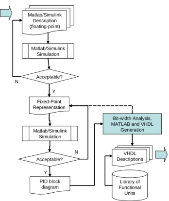
III. PROPOSED METHODOLOGY
Fig. 2 shows the proposed methodology, where the Mat-lab/Simulink [ 14 ] environment is used for modeling and simulation. The methodology starts by simulating the control system (when working with a time-invariant process, the PID parameters are firstly tuned using Matlab/Simulink) using floating point numerical representations (IEEE 754 double format). Terminated this first step with success (i.e., control stability), the same control system model is simulated with fixed-point representation using the fixed-point toolbox in-cluded in the Matlab/Simulink [14] environment. At this time we can compare the system responses obtained from simula-tions with floating- and fixed-point representasimula-tions. We can also check the influence of using different number of bits in the system stability. Note that, in this step, the number of bits for each part, integer and fractional, is uniform for all op-erators and operands of the system. In this step we also
ex-plore the fixed-point representation of the PID parameters needed to avoid system instability.
This step furnishes the minimum integer and fractional bits required by the uniform fixed-point representation. Those minimums will be used by the static bit-width analyzer to optimize the fixed-point representations with specialized formats for different components of the architecture.
Matlab/Simulink Description (floating-point) Matlab/Simulink Simulation Fixed-Point Representation Acceptable? Matlab/Simulink Simulation Acceptable? PID block diagram VHDL Descriptions Library of Functional Units Bit-width Analysis, MATLAB and VHDL Generation N Y Y N
Fig. 2. Proposed methodology.
The test of the system is performed with a reference signal,
ref (Fig. 1a), composed by a set of steps with arbitrary
am-plitudes and durations (first signal in Fig. 3). This reference can be established before the test, or generated randomly. As an example, we present in Fig. 3 the system output for dif-ferent representations. Although not shown, in this type of systems beyond a certain limit the system gets unstable and oscillations are present on the response.
In this specific case, the control process is a discrete time invariant model obtained by sampling and hold (ZOH – Zero
Order Hold), with a given frequency, a continuous process
chosen from the test set used by Åström and Hägglund [1] as examples of representative plants for the dynamics of typical industrial processes; it is a third order process with multiple poles.
Concluded this step with uniform fixed-point representa-tions, we can explore different numbers of bits for each op-erator/operand of the architecture. Without tools to help the exploration, this specialized analysis is very time-consuming because a large number of combinations of bits for integer and fractional parts is required. Due to this fact, our meth-odology includes a step where a static analysis of the number of bits is performed. 0 20 40 60 80 100 120 −200 −100 0 100 200 0 20 40 60 80 100 120 −200 −100 0 100 200 Time (s) 0 20 40 60 80 100 120 −200 −100 0 100 200
Fig. 3. System response: (a) reference signal; (b) floating-point response; (c) uniform fixed-point (<18,7>: 18 bits of integer part and 7 bits of fraction) response and specialized fixed-point response.
Although optimal schemes have been considered (e.g., [15], [16] and [17]) we included in our tool a mix of a simple static analyzer and bit-width information collected from simulations with uniform fixed-point representations.
The static analyzer is a Java application that computes the bit-widths over a dataflow graph (DFG) representation of the PID controller architecture (each node represent an operator, register or variable, and each edge an operand). The analyzer iteratively traverses the DFG doing forward and backward propagations and error calculations. We use static value range propagation [18] also known as data-range propagation to determine amplitude data-ranges. Value range propagation has been successfully used before [19][20]. Static bit-width analysis has been an active focus of research. We based our analyzer in the work presented in [20].
We start with minimum values and update the range values according to the operator of the DFG node. The analyzer uses information from the user such as input/output representa-tions, maximum integer bit-widths (necessary when dealing with feedback cycles), maximum fractional bit-widths, and maximum absolute errors in input/outputs. The maximum integer bit-widths are collected after achieving the minimum uniform fixed-point representation by simulation.
Fig. 4 shows the algorithm used for static bit-width analy-sis. The stop condition of the iterative procedure is triggered when both propagations do not impose changes on the value range analysis, or the maximum number of iterations is reached, or the errors are below a certain value defined by the user. An error analysis use error models for each operation on the DFG such as the one presented in [20]. The error calcu-lation step assumes all the operation outputs are truncated to the precision used. A step is responsible to perturb fractional parts (adding each time one bit to DFG edges recognized as the main sources of errors). We have plans to study the effect of other heuristics on perturbing fractional parts (adding and subtracting bits) since our method may not achieve close-to-optimal solutions. Notice, however, that studies are needed to evaluate techniques to check, without simulations,
if the stability of the system is maintained after quantization.
Inputs: DFG representing the design annotated with the word-lengths for all inputs and outputs;
Output: DFG with edges labeled with fixed-point representations;
1. Simulate the system using floating-point representations.
Output the maximum ranges of the variables in the PID controller. They are used as a starting point for the next step;
2. Find the minimum uniform fixed-point representation for
the design that maintains the stability of the system and producing acceptable response errors (this is currently done by simulation and comparison to floating-point responses);
3. Define as the maximum bits for integer and fractional part
the ones obtained in 2;
4. Specify maximum acceptable output errors;
5. do {
6. do forward propagation until a fixed-point is reached;
7. do backward propagation until a fixed-point is reached;
8. do error analysis;
9. if (errors not acceptable)
10. perturb fractional parts;
11. } while (changes in forward- or back-propagation or the
number of iterations reaches the limit or error not acceptable);
Fig. 4. Bit-width analysis algorithm.
The PID controller includes a cycle related to the integra-tion part. This tradiintegra-tionally imposes difficulties for static bit-width analysis and usually requires the use of simulation data to quantify the bits needed for that PID section. The problem here is different to the bit-width analysis performed to algorithms (described in a programming language). There in the presence of statically unbound loops a tool may decide to assign the worst case bit-widths (the ones related to the data types used in the program) [20]. In our case the worst case bit-widths are not known before simulation and the loop will be iterating forever.
Our backward propagation does not propagate from outer DFG nodes to cyclic DFG regions, since that would cause precision problems due to truncation. In this case cyclic DFG regions are identified and their DFG nodes annotated ac-cordingly.
With this step accomplished we have a specialized number of bits for each operator/operand. The values obtained are then exported to Matlab/Simulink model for validation using the “quantizer” and “quantize” functions included in Filter Design Toolbox [14].
The VHDL generator (gray box in Fig. 2) is responsible, based on a VHDL library of operators, for the generation of the VHDL structure to be synthesized (in this work, XST - Xilinx® Synthesis Technology tool - included in the Xilinx ISE 7.1i environment, is used). Each functional unit (FU)
from the operator library was described using the VHDL parameterization facilities allowing the generation of FUs completely specialized. The library also includes versions of the FUs with saturation. Those versions, however, require more resources and therefore its use must be evaluated before a decision. At the moment, the tool generates the architecture with FUs with or without saturation (it seems us statically difficult to evaluate the necessity to use of this type of units). The simulation results obtained with the generated VHDL (in this work, the ModelSim® simulator was used) are then compared with the results obtained form Matlab/Simulink simulations.
Note that, integration of the VHDL simulator inside the Matlab/Simulink [14] model should be considered and can be helpful for validation of the architecture, before its imple-mentation in FPGA.
IV. EXPERIMENTAL RESULTS
In this section we show how we evaluated the proposed methodology and the results achieved. The continuous plant from which we obtained the equivalent discrete one has the following transfer function: G(s) = 1/(s+1)3. The sampling period Ts was empirically chosen based on the magnitude of the poles time constants, for this case we used Ts = 10 ms.
We consider reference and input/output signals repre-sented with 10 bits for integer part (two’s complement rep-resentation) and 0 bits for fractional part (<10,0>).
We show results for three implementations of PID con-trollers:
- Example A: considers the PID structure where a0, a1 and a2 are furnished as inputs (see equation (1)); - Example B: considers the PID structure where Kc, Ti
and Td are furnished as inputs (a0, a1 and a2 are calcu-lated internally by the hardware circuitry);
- Example C: considers an auto-tuning scheme that adapts the Kc, Ti and Td values according to the responses. Based on step response of the Ziegler-Nichols rule [1], we obtained the Kc, Ti and Td parameters for example B, from which we evaluate the a0, a1, a2 coefficients for example A. For example C we have adapted the Ziegler-Nichols [1] tuning rule based on step response.
The circuits for the PID controllers have been obtained by logic synthesis and place and route using Xilinx ISE 7.1i, from the VHDL representation generated by the static ana-lyzer. We use a Xilinx Spartan-3 xc3s1000-ft256-5 FPGA [21]. The results presented herein are estimations directly obtained from Xilinx ISE 7.1i.
When considering specialized fixed-point representations, there are 12 and 22 points to be defined to a certain precision for the Examples A and B, respectively. Each variable needs two parts (integer and fraction) to specify using for each part bit-width values from 0 to a MAX value.
Table I shows the number of functional units used to im-plement the Examples A and B. In the table MUL, ADD, REG, SUB, DIV, SHL, INC, NEG and LIM identify,
re-spectively, multipliers, adders, registers, subtractors, divid-ers, shift by one, increment by one, negation units, and lim-iters.
TABLE I
NUMBER OF FUNCTIONAL UNITS FOR EACH EXAMPLE
MUL ADD REG SUB DIV SHL INC NEG LIM
Ex. A 3 3 8 1 - - - - 1
Ex. B 6 3 9 2 2 1 2 1 1
Example A
The floating-point values of the a0, a1 and a2 coefficients are: 223.1538, -441.4616 and 218.3344, respectively. In the examples with fixed-point representations we use for a0, a1 and a2 <9,7>, <10,6> and <9,6>, respectively. Those repre-sentations permit to represent those values as 223.1484, -441.4688 and 218.3281. Note that to represent the original parameters with full-precision we would need 44, 43 and 45 bits for the fractions.
For uniform fixed-point representation it was used 18 bits for the integer part and 7 bits for the fractional part (<18,7>) for all operands (a0, a1 and a2 included) and operators. This representation has been found to be the lowest one keeping the system stable. The representation uses a total of 345 bits. The specialized representation obtained using the static bit-width analyzer uses a total of 273 bits (a reduction of 20.9% of bits that implies a reduction of 48.5% of 4-LUTs). Both implementations achieve none errors when compared to the floating-point implementation using the same values for
a0, a1 and a2 for the reference signal presented. When
compared to the original floating-point values, although stable, both representations have a mean relative error of 7.9%. Note that further reductions of bit-widths make the system unstable. Based on this, we can conclude that in this kind of digital systems error metrics (relative, absolute, etc.) may play a secondary role since they may not have the im-portance as in digital filter design. Here, we are firstly con-cerned with stability and then with precision.
Table II shows the results obtained for six implementations of the PID controller described in this paper. Those imple-mentations consider arithmetic units without saturation, saturations only on ADDERs and SUBs, and on all the arithmetic units (ADDERs, SUBs and MULTs).
The results show an increase from 26% to 38% of flip-flops (FFs), 1.41x and 2.87x more 4-LUTs, and 3x to 4x more MULT18x18s, between specialized and uniform bit-widths. With respect to maximum clock frequency, the results show a decrease from 11% to 29% between special-ized and uniform bit-widths. When using arithmetic units with saturation the results show significant increase in the number of resources (4.3x and 5.7x for the specialized, and 2.1x and 3.7x for the uniform) and a decrease in the maxi-mum clock frequency (35% and 45% for the specialized, and 19% and 27% for the uniform). Fig. 5 shows the ratios be-tween the obtained results.
TABLE II
FPGA RESULTS FOR UNIFORM AND SPECIALIZED FIXED-POINT
REPRESENTATIONS (EXAMPLE A) Fixed-Point Repre-sentation Max. Freq (MHz) #4-LUTs #Slices #FFs #MULT 18x18
specialized w/o sat 73.31 62 84 106 3 specialized w/
ADD-SUB sat 47.33 267 191 114 3
specialized w/ all sat 40.64 358 227 118 3 uniform w/o sat 52.40 178 163 146 9 uniform w/
ADD-SUB sat 38.63 376 260 142 9
uniform w/ all sat 32.39 665 380 148 12
0 2 4 6 8 10 12
variable w/o sat variable w/
ADD-SUB sat
variable w/ all sat
uniform w/o sat uniform w/ ADD-SUB sat
uniform w/ all sat Max Freq
4-LUTs Slices FFs MULT18x18
Fig. 5. Ratio of resources used and maximum clock frequency for the exam-ples (with respect to the normalized results obtained for the “specialized w/o sat” case).
Example B
When considering the complete PID (with hardware cir-cuitry to calculate the a0, a1 and a2 coefficients) with uni-form fixed-point representations of <18,8> the RMS (Root Mean Square) error, obtained based on the difference be-tween fixed- and floating-point system output (y) values, was 4.505. This error is null when using the representation <18,25>. For specialized fixed-point representations we used as maximum bit-widths <18,8>. The RMS error obtained with specialized fixed-point representations was 0.216.
The implementation with specialized fixed-point repre-sentations permitted to reduce the total number of bits used from 654 to 478 (26.9%). The FPGA results are shown in Table III. There is a tremendous increase in resources for the Example B due to the need of two dividers (the results con-sider a combinational divider without pipelining). In this case it is obvious we need to consider sharing of some functional units in the same PID controller or among the PID controllers existent in the target system. Higher clock frequencies can be achieved using dividers with pipelining stages.
TABLE III
FPGA RESULTS FOR UNIFORM AND SPECIALIZED FIXED-POINT
REPRESENTATIONS (EXAMPLE B) Fixed-Point Rep-resentation Max Freq. (MHz) #4-LUTs #Slices #FFs #MULT 18x18 Uniform 3.964 5074 3584 209 18 Specialized 4.494 3568 2189 116 14 Example C
the PID controller and an auto-tuning technique (a relevant characteristic for mobile robotics due to the changes in the environment that may occur) based on step response Ziegler-Nichols rule.
The system architecture implemented as a SoC (sys-tem-on-a-chip) solution, with an Altera Stratix EP1S10F780C6ES FPGA [22], uses one Nios II softcore microprocessor responsible to execute the auto-tuning algo-rithm (the algoalgo-rithm has been translated from Matlab to C language) and to calculate the a0, a1 and a2 PID coefficients (i.e., the software component includes the calculation of the coefficients from the Ts, Td, Ti and Kc values). The Nios II is connected to the PID architecture (a hardware core obtained from the VHDL description output from the generator) using the Avalon bus. This version of the software algorithm uses floating-point data types. Fixed-point values are read and written to the PID core by the microprocessor.
Table IV shows the resources used by the entire system and the maximum frequency of the PID controller core. The re-sources include a timer connected to the PID controller that is responsible to control the PID registers each sampling period, Ts.
The results indicate that with the microprocessor running at 50 MHz it is capable to execute each auto-tuning iteration in 0.235 ms. This means that with a sampling period of 50 ms, a single Nios II could perform auto-tuning to several distrib-uted PID controllers.
With an EP1S80 Stratix FPGA we can include in the same FPGA one Nios II and about 7 or 28 PID controller cores using the uniform or the specialized fixed-point representa-tions, respectively. Those maximum numbers of PID con-troller cores are constrained by the number of DSP elements of the FPGA. Using logic elements (LEs) to implement the multipliers of the architecture would have resulted in much more PID controller cores in the same FPGA. However, that would certainly decrease the maximum clock frequency achieved.
TABLE IV
RESULTS USING AN ALTERA FPGA WITH ONE NIOS II AND THE PID
ARCHITECTURE (EXAMPLE C): LES REPRESENT LOGIC ELEMENTS; DSP
ELEMENTS REPRESENT 9X9 BITS INTEGER MULTIPLIERS.
Architecture #LEs Memory
(Kbits) #DSP Elements Max Freq. (MHz) Uniform (including Nios II) 5651 (53%) 571,136 (62%) 32 (67%) 57.72 Uniform (without Nios II) 459 (4%) 0 (0%) 24 (50%) 57.72 Specialized (including Nios II) 5399 (51%) 571,136 (62%) 14 (29%) 57.17 Specialized (without Nios II) 238 (2%) 0 (0%) 6 (43%) 57.17 Overall Comments
The overall results for the eight implementations (related to the cases shown in Table II and III) reveal that when using our approach an increase of 24% on the maximum system
clock frequency was achieved on average, and reductions on FPGA resources of 37.8% (Slices), 26.6% (FFs) and 57.6% (MULT18x18s) were achieved on average.
Note that the FPGAs being used, although not the most advanced and largest commercially available, can easily accommodate various PID controllers.
V. CONCLUSIONS
This paper presents a methodology to design PID controllers when targeting FPGA-based systems. The methodology exploits fixed-point representations, uniform or specialized, in order to reduce the number of resources needed still achieving stable control systems. Resource savings are im-portant in order to embed several PID controllers and other system components in the same FPGA. Resources savings are also an important factor to reduce power dissipation and energy consumption, important goals for embedded systems in certain mobile robotic systems. The preliminary tests show the effectiveness of the methodology on both shortening design time and reducing the number of resources.
However, there are some aspects needing further research work. Evaluations of less conservative word-length analysis techniques are needed. The use of arithmetic units with saturation requires additional hardware resources and studies should be done in order to analyze the trade-off between the use of saturation and the use of more bits of representation. The sharing of multiplier units might also be needed when there are not enough on-chip multipliers to implement all the PID controllers and additional components on the system.
Further work will also address time-variant processes and the integration of more advanced auto-tuning techniques. We also have plans to evaluate the capability of auto-tuning al-gorithms to increase the immunity of the PID controller to quantization errors.
ACKNOWLEDGMENTS
We acknowledge the donations by Xilinx and Altera of both software environments and development boards.
REFERENCES
[1] K. Åström, T. Hägglund, “PID Controllers: Theory, Design, and Tun-ing,” in Instrument Society of America, Research Triangle Park, NC, USA, 2nd, 1995.
[2] Michael A Johnson, Mohammad H Moradi, and J Crowe, PID control : new identification and design methods, Springer, New York, 2005. [3] F. Michaud, and D. Letourneau, “Mobile robot that can read symbols,”
in Proceedings 2001 IEEE International Symposium on Computational Intelligence in Robotics and Automation, 29 July-1 Aug. 2001, pp. 338-343.
[4] I. E. Paromtchik, U. Rembold, “A practical approach to motion gen-eration and control for an omnidirectional mobile robot,” in IEEE In-ternational Conference on Robotics and Automation, 8-13 May 1994, vol.4, pp. 2790-2795.
[5] H. Zhang, G. Trott, R. P. Paul, “Minimum delay PID control of inter-polated joint trajectories of robot manipulators,” in IEEE Transactions on Industrial Electronics, Volume 37, Issue 5, Oct. 1990, pp. 358-364. [6] F. Caccavale, C. Natale, B. Siciliano, and L. Villani, “Integration for the
IEEE Robotics Automation Magazine, Vol. 12, Issue 3, Sept. 2005, pp. 53- 64.
[7] R.-X. Chen, L.-G. Chen, and L. Chen, “System Design Consideration for Digital Wheelchair Controller,” in IEEE Transactions on Industrial Electronics, Vol.47, No.4, Aug. 2000, pp. 898-907.
[8] L. Samet, N. Masmoudi, M.W. Kharrat, and L. Kamoun, “A Digital PID Controller for Real Time and Multi Loop Control: a comparative study,” in Proceedings IEEE Int’l Conference on Electronics, Circuits and Systems (ICECS’98), Vol.1, Sep. 7-10, 1998, pp. 291-296. [9] Sungsu Kim, and Seul Jung, “Hardware Implementation of a Real Time
Neural Network Controller with a DSP and an FPGA,” in Proceedings IEEE Int’l Conference on Robotics and Automation (ICAR’04), New Orleans, USA, April, 2004, pp. 4639- 4644.
[10] W. Zhao, B.H. Kim, A.C. Larson and R.M. Voyles, “FPGA Imple-mentation of Closed-Loop Control System for Small-Scale Robot,” in Proceedings Int’l Conference on Advanced Robotics (ICAR’05), v. 1, 2005.
[11] David Gwaltney, Ken King, and Keary Smith, “Implementation of Adaptive Digital Controllers on Programmable Logic Devices,” in 5th Annual Military and Aerospace Programmable Logic Devices (MAPLD) Int’l Conference, 10-12 Sep. 2002, Laurel, MD, USA. [12] J. Li, and B.-S. Hu, “The Architecture of Fuzzy PID Gain Conditioner
and Its FPGA Prototype Implementation,” in Proceedings 2nd IEEE Int’l Conference on ASIC, Oct. 21-24, 1996, pp. 61-65.
[13] M. Petko, G. Karpiel, “Semi-automatic implementation of control algorithms in ASIC/FPGA,” in Proceedings Emerging Technologies and Factory Automation (ETFA'03), Sept. 2003, vol.1, pp. 427- 433. [14] The Mathworks Inc., http://www.mathworks.com
[15] George A. Constantinides, Peter Y.K. Cheung, and Wayne Luk “Op-timum and Heuristic Synthesis of Multiple Word-length Architectures,” in IEEE Transactions on Very Large Scale Integration Systems, 13:(1), 2005, pp.39-57.
[16] George A. Constantinides, Peter Y.K. Cheung, and Wayne Luk, Syn-thesis and Optimization of DSP Algorithms, Kluwer Academic Pub-lishers, 2004, pp.1-164.
[17] K. Han and B. L. Evans, “Optimum Wordlength Search Using Sensi-tivity Information,” in EURASIP Journal on Applied Signal Process-ing, special issue on Design Methods for DSP Systems, vol. 2006, no. 5, 2006, pp. 103-116.
[18] William H. Harrison, “Compiler Analysis of the Value Ranges for Specializeds,” in IEEE Transactions on Software Engineering, 3(3), May 1977, pp. 243-250.
[19] M. Stephenson and J. Babb and S. Amarasinghe, “Bitwidth Analysis with Application to Silicon Compilation,” In Proceedings of the SIGPLAN Conference on Programming Language Design and Im-plementation, Vancouver, British Columbia, June 2000.
[20] A. Nayak, M. Haldar, A. Choudhary, and P. Banerjee, “Precision and error analysis of MATLAB applications during automated hardware synthesis for FPGAs,” in DATE 2001, pp. 722-728.
[21] Xilinx, Inc. http://www.xilinx.com [22] Altera, Inc. http://www.altera.com