Analysing the critical orientation of seismic loading in 3D
buildings: preliminary results for constant lateral forces
Despoina Skoulidou1, Xavier Romão2
Department of Civil Engineering, Faculty of Engineering University of Porto, Porto, Portugal ([email protected], 2[email protected])
Abstract
The angle of seismic excitation has been proven to be an important factor when analysing the 3D behaviour of buildings. However, modern earthquake-related standards only cover partially the effects of this factor and practicable results of relevant studies are still limited. The proposed paper focuses on the determination of the critical angle of incidence based on the building's structural characteristics. An analytical expression is developed to define the critical angle for the case of single storey buildings and a special category of multi storey buildings under constant lateral forces assuming linear elastic behaviour of the structures.
Subject Headings. Civil Engineering, Engineering Structure, Seismic Monitoring Author Keywords. Angle of Incidence, Earthquake Loading, Three-Dimensional
Analysis, RC Buildings
1. Introduction
In real earthquake events the excitation angle of the seismic action is generally unknown a priori. Thus, it is prudent to perform seismic analysis by adopting a three-dimensional (3D) structural model and the angle of seismic incidence (ASI) that induces the highest structural demand. Although the consideration of such an angle, i.e. the critical angle of seismic incidence (ASIcrit), is required by earthquake-related standards (e.g. Eurocode 8 (2004)), no
methodology is currently included in standard provisions for its determination. Alternatively, in order to account for the most unfavourable scenario without performing parametric analyses for every ASI, standards prescribe the simultaneous application of the earthquake loading along two orthogonal directions that coincide with the building’s structural axes. Furthermore, in case the seismic action is represented by timewise non-simultaneous peak values, the combination of the responses of each direction is subsequently performed using well-known directional combination rules (Newmark 1975; Rosenblueth and Contreras 1977). The efficiency of these provisions as well as studies for the determination of the ASIcrit have
been extensively addressed by several researchers over the past decades.
In the domain of linear elastic analysis, the ASIcrit was studied for response spectrum analysis
(RSA) and for translational components having arbitrary shapes (Smeby and Der Kiureghian 1985; Lopez and Torres 1997). Particularly, it was proven that the ASIcrit does not depend on
the ratio of the two horizontal components when they have the same shape nor on the arbitrary vertical component. For the determination of the ASIcrit, prior structural analyses
with the response spectra under consideration were required to be carried out. In the same study the authors also demonstrated that different demand parameters obtain their
maximum values for different ASIcrit. Menun and Der Kiurengian (1998) introduced the
the traditional practice of considering only one ASI and using the directional combination rules (e.g. the 100/30 percentage rule) leads to unconservative results. Several studies dealing with different structures and various demand parameters can be found in the literature that demonstrate the inadequacy of the previously mentioned standard provisions (e.g. see Fernandez-Davila et al. 2000; Lopez et al. 2001; Menun and Der Kiureghian 2000). Based on those conclusions and still in the domain of response spectrum analysis, Lopez et al. (2000) determined upper boundaries for the structural demand with respect to the square root of the sum of the squares of the response for several structural demand parameters implementing the CQC3 rule. In the context of time history analysis (THA), the ASIcrit and the
corresponding maximum response were determined by Athanatopoulou (2005) for structures with linear elastic behaviour. The author also showed that maximum values of each demand parameter are obtained for different ASIscrit. Such as for the case of RSA, the determination of
the ASIcrit was only achieved after performing preliminary analyses of the structure using the
ground motion records under consideration. Additionally, the inadequacy of considering only one orientation of the seismic action and using the directional combination rules was also shown by Kostinakis et al. (2013) using results of THA. Furthermore, studies dealing with the lateral force analysis (LFA), which is considered the simplest as well as the most conservative method of analysis to determine structural demand under earthquake loading, showed that the demand may be underestimated if the ASIcrit is not taken into account (Morfidis et al. 2008;
Quadri and Madhurin 2014).
When nonlinear analysis is performed, the determination of the ASIcrit can no longer be
achieved by performing preliminary analyses (Cantagallo et al. 2012; Fontara et al. 2015). Applications involving the nonlinear time history analysis (NLTHA) of several structures showed that the inelastic structural demand may be substantially underestimated when the ground motion components are applied along the building's global structural axes (MacRae and Mattheis 2000; Zaghlool et al. 2001; Hosseini and Salemi 2008; Fernandez-Davila and Cruz 2008; Magliulo et al. 2014). Moreover, it was shown that directional combination rules are highly dependent on the selection of the ASI and may considerably underestimate the structural response. In order to take into account the variability of the ASI in NLTHA, Lagaros (2010) implemented multicomponent incremental dynamic analysis and showed that considering thirty ASIs and record pairs is adequate enough to account for the randomness of both the record and the ASI. More recently, Sebastiani et al. (2014) introduced a simplified approach to evaluate the ASIcrit by performing parametric pushover analyses in single degree
of freedom systems representing a multi degree of freedom structure in an attempt to reduce the computational effort.
Overall, past research has shown that for all methods of analysis and material behaviour the maximum response may not occur when the ground motion components are applied along the global structural axes. Furthermore, available results also showed that existing directional combination rules may underestimate the true structural response. Since no correlation has been found yet between the building's configuration and the expected response due to bidirectional seismic input, practitioners must perform various analyses in order to simulate several ASIs and establish the relevant critical orientation; with the latter being particularly demanding when nonlinear material behaviour is considered. Existing methods developed to explicitly determine the ASIcrit correspond to structures with linear elastic behaviour and still
require the results of preliminary analyses. As a result, the process of seismic design or safety assessment of a structure may result in an overly time-consuming numerical procedure. It is
thus necessary to focus on the definition of new methods in order to account for the ASIcrit in
a more robust and efficient way.
In light of this, a preliminary approach for the direct calculation of the ASIcrit is presented in
the context of linear elastic analysis and for constant static lateral loading. The proposed procedure is defined in the context of the seismic safety assessment of existing buildings and establishes critical demand criteria for single storey buildings and for a special category of multi-storey buildings based on maximum storey displacements. The proposed approach
defines an expression to determine the ASIcrit based only on the geometrical and material
characteristics of the building, thus being independent of the external static loading.
2. Review of concepts regarding the static behaviour of single storey buildings
The developed methodology for the determination of the ASIcrit is based on the static
behaviour of 3D single storey buildings, non-symmetric in plan, as described by Roussopoulos (1932). The behaviour of single storey buildings is of particular importance in the study of earthquake resistant structures, since it was used extensively in the past and it is still used nowadays in the framework of LFA as a proxy for the behaviour analysis of multi-storey structures. For this reason, some basic concepts of single storey structures and of their behaviour under static loading are presented first to help illustrating the rationale. The mechanical behaviour of the materials will be considered to be linear elastic and the floor will be considered to be in-plane rigid and out-of-plane flexible. Furthermore, the vertical elements will be considered to be axially rigid. Single storey buildings with the aforementioned properties always possess an elastic centre Cs and principal axes (I, II, III), where Cs is the
intersection of the vertical principal axis III (also termed elastic axis) with the floor diaphragm (Roussopoulos 1932; Makarios and Anastassiadis 1998).
For a single storey building with the aforementioned properties, the total number of degrees of freedom (dof) representing global behaviour can be considered to be three: two translational and one rotational. As a result, the horizontal stiffness of the structure can be described by a 3×3 matrix with respect to an arbitrary reference system O (X,Y,Z), where X-Y is the horizontal plane, Z is the vertical axis and O is their intersection point. For an arbitrary horizontal loading vector [FX, FY, MZ] T, the following static equilibrium has to be satisfied:
XX XY XZ X X YX YY YZ Y Y ZX ZY ZZ Z Z K K K u F K K K u F K K K θ M ⋅ = (1) where Kij are the stiffness matrix coefficients and [uX uY θΖ] T is the displacement vector with
respect to the O (X,Y,Z) reference system.
Based on the properties of Cs for single storey buildings (Roussopoulos 1932; Makarios and
Anastassiadis 1998), it is always possible to define a special reference system Cs (I, II, III) with
respect to which the stiffness matrix takes a diagonal form. This reference system is the principal system of the structure and is defined by a horizontal plane I-II, the vertical axis III and their intersection point Cs. In the principal reference system, the static equilibrium takes
the form defined by:
s s I I I II II II III C C K 0 0 u F 0 K 0 u = F 0 0 K θ M ⋅ (2)
where KI, KII, KIII are the principal stiffness matrix coefficients and [uI uII θCs] T and [FI FII MCs] T
are the displacement and the loading vectors, respectively, with respect to the Cs (I, II, III)
principal reference system.
The principal stiffness matrix is derived from translation and rotation of the initial stiffness
matrix defined by Eq.Error! Reference source not found. and the location of the principal
system is determined from the conditions KII,III = 0, KI,III = 0 and KI,II = 0. The coordinates of Cs
with respect to the initial system are calculated by the first two conditions, while the third condition defines the rotation angle ω of the principal axis I with respect to the structural axis X (Anastassiadis 1989).
3. Determination of the critical angle of incidence in single storey buildings
3.1. Principal axes parallel to global axes
In the special case where all force-resisting elements have their axes along two perpendicular
directions X and Y, the stiffness coefficients ΚΧΥ and ΚΥΧ of
Eq.Error! Reference source not found. are equal to zero. Therefore, the angle ω is also equal
to zero (ω = 0o) and the principal axes are derived from the initial global axes only by
translation, i.e. without rotation.
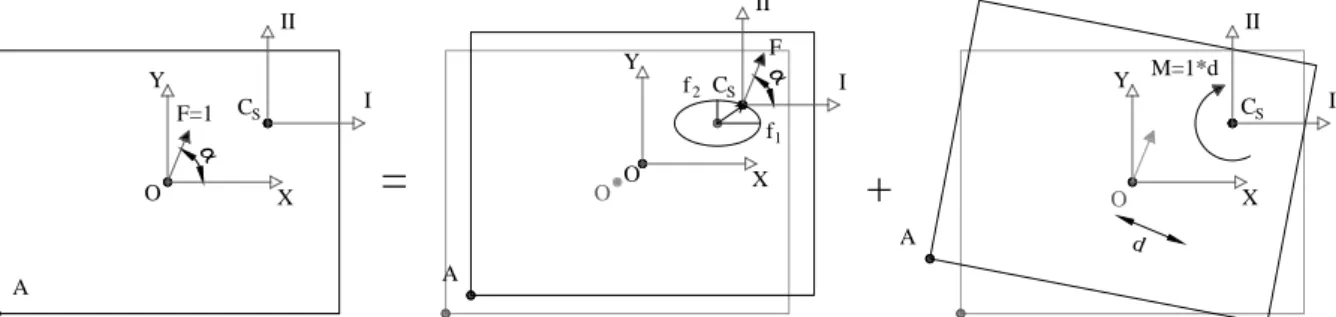
Based on the properties of Cs (Roussopoulos 1932; Anastassiadis 1989), a unit static force
passing through the centre of stiffness causes a translation without rotation of the floor diaphragm. During the rotation of a unit static force around Cs, the peak displacement vector
defines an ellipse with axes I, II and lengths of the semi-axes equal to fΙ (= 1/KI) and fΙΙ (= 1/KII),
respectively. In addition, a unit torsional moment about a vertical axis causes rotation of the
diaphragm about Cs. Therefore, a horizontal static force F rotating around any point of the
diaphragm, e.g. point O in Figure 1, will cause an elliptic translation of Cs and a rotation of the
diaphragm around Cs. Hence, the overall displacement of the floor may be obtained as a
superposition of two states of pure translation within the planes (I-III, II-III) and of one state of pure rotation about the axis III, as illustrated in Figure 1. The value of the moment that causes rotation will depend on the orthogonal distance d between F and Cs (Figure 1).
Figure 1: Displacement of a single storey building subjected to a horizontal unit
static force applied at O with an arbitrary direction with respect to the structural axes X-Y. The principal axes I-II are parallel to the structural axes
According to the previously mentioned, the vector of displacements of Cs [ Cs X
u Cs Y
u θZ]T due to
the rotation of a unit static force about O may be calculated using:
M=1*d d
=
F=1 O X Y I II O CS O+
f1 f2 A I II CS F A I II CS A X Y X Y Os s Z s s ⋅ ⋅ C I X C Y II C C III cos(α) Κ u sin(α) u = Κ θ cos(α) y -sin(α) x Κ (3)
where yCs and xCs represent the coordinates of Cs with respect to the global reference system
O (X,Y,Z) and α is the angle of the horizontal static force with respect to the global X axis, which also coincides with the principal axis I. The displacement of a generic point of the diaphragm, e.g. point A in Figure 1, may then be calculated according to Eq. 4 which defines the displacement of A as a function of the displacement of Cs based on rigid body kinematics:
Cs Cs Z Z Z Z A A Y X A Y Y A u -y θ u u = u +x θ θ θ ⋅ ⋅ (4) where yA and xA are the coordinates of A with respect to the principal coordinate system Cs (I,
II, III) which, in the current case, is parallel to the global system (ω=0o). Subsequently, the total
resultant horizontal displacement of A, uA, can finally be derived by applying the Pythagorean
Theorem:
( ) ( )
2 2 A A A X Y u = u + u = 2 2 CS CS CS CS A A I III II III(cos(α) y -sin(α) x ) (cos(α) y -sin(α) x )
cos(α)-y + sin(α)+x Κ K Κ K ⋅ ⋅ ⋅ ⋅ (5)
It can be seen that the displacement of A is defined based on the known geometrical and mechanical characteristics of the structure and it is a function of the unknown angle α. Consequently, the angle that leads to the maximum displacement can be calculated straightforwardly by differentiating Eq. 5 with respect to the angle α and by setting this derivative equal to zero:
A
crit
du = 0 α
dα → (6)
The calculated angle αcrit corresponds to the ASIcrit for the displacement of the generic point
A. Since the maximum displacement of the whole diaphragm will occur at the point with the largest distance from Cs, the ASIcrit of that point will coincide with the ASIcrit of the building
when considering the maximum displacement of the building as a measure of the global building performance.
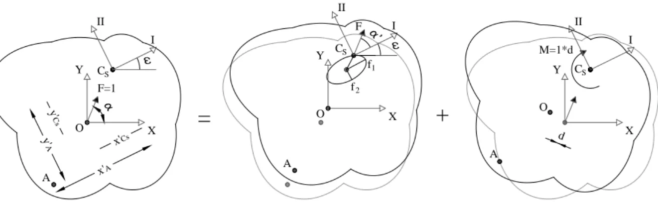
3.2. Principal axes not parallel to global axes
Generally, structures may have structural elements that do not have their local axes along two perpendicular directions. Hence, a common reference system may be difficult to be defined. Also, in this case, the terms ΚΧΥ and ΚΥX of Eq. 1, which correspond to a global - arbitrarily
defined - reference system, are no longer equal to zero. Therefore, the angle ω is no longer equal to zero and the principal axes I and II are rotated with respect to axes X and Y, as illustrated in Figure 2.
Figure 2: Displacement of a single storey building subjected to a horizontal unit
static force applied at O with an arbitrary direction with respect to the structural axes X-Y. The principal axes I-II are not parallel to the structural axes
For the implementation of the methodology presented in Section 3.1 the determination of the coordinates of Cs, the angle ω and the principal stiffness matrix are again performed according
to the procedure presented in Section 2. Subsequently, the coordinates of Cs with respect to
the reference system O (X,Y,Z) are determined in the rotated system of axes (x'Cs, y'Cs), as well
as the coordinates of point A (x'Α, y'Α) with respect to the principal coordinate system Cs (I, II,
III). For structures with principal axes that are not parallel to the global axes, the displacement vector of Cs due to the rotation of a unit force about O is defined by:
CS I X CS Y II Z CS CS III cos(α') Κ u sin(α') u = Κ θ cos(α') y' -sin(α') x' Κ ⋅ ⋅ (7)
where α' represents the angle of the static force with respect to the principal axis I shown in Figure 2. The total resultant displacement of a generic point A (shown in the same figure) can then be calculated using rigid body kinematics by:
( ) ( )
2 2 A A A X Y u = u + u = 2 2 CS CS CS CS A A I III II III(cos(α') y' -sin(α') x' ) (cos(α') y' -sin(α') x' )
cos(α')-y' + sin(α')+x'
Κ K Κ K ⋅ ⋅ ⋅ ⋅ (8) Similarly to the procedure presented in Section 3.1, the ASIcrit of the static horizontal force
that leads to the maximum response in terms of horizontal displacements of the diaphragm
can be derived by differentiating Eq.Error! Reference source not found. with respect to the
angle α' and by solving this derivative equal to zero. Since the angle α' is defined with respect to axis I of the principal coordinate system, it needs to be converted into the angle α defined in terms of the global coordinate system O (X,Y,Z) by adding the angle ω:
α α' = + ω (9)
4. Determination of the critical angle of incidence in multi-storey buildings
General multi-storey buildings do not have an elastic axis or principal bending directions (Riddel and Vasquez 1984; Anastassiadis 1989), therefore the methodology presented in Section 3 can’t be fully implemented for this type of structures. Nevertheless, there are special categories of multi-storey buildings for which those concepts are still usable. For those cases,
y' Cs y' A x'A x'Cs X Y O F=1 I II CS d A f1 f2 M=1*d I II CS A O F
=
+
A I II O CS X Y X Ythe expressions connecting the ASIcrit with the geometrical and mechanical characteristics of
the buildings are still applicable after performing some modifications. Buildings for which an elastic axis and principal bending planes can be defined belong to one of the following categories of systems (Riddel and Vasquez 1984; Makarios and Anastassiadis 1998; Athanatopoulou and Doudoumis 2008): systems with two horizontal axes of symmetry in plan view, isotropic systems, ortho-isotropic systems and complex-isotropic (coaxial) systems. All the previously mentioned systems have principal bending planes (I-III, II-III) the intersection of which defines the elastic axis III of the system. Furthermore, the elastic axis of multi-storey buildings possesses elastic properties similar to those of the elastic axis of single storey buildings, summarized by Makarios and Anastassiadis (1998). Given these properties, the static response of the system is obtained by the superposition of two states of pure bending within the planes (I-III, II-III) and of one state of pure torsion about the axis III.
Generally, any N-storey building satisfies the following static equilibrium with respect to an arbitrary reference system (X,Y,Z) (Anastassiadis 1985):
xx xy xz x x yx yy yz y y zx zy zz z z K K K u f K K K u = f K K K θ m ⋅ (10) where u̲x, u̲y, θ̲z are the N-dimensional vectors of translations uxi, uyi and rotations θzi with
respect to the Xi, Yi, Zi axes, respectively, with i = 1 to N. Furthermore, f̲x, f̲y, m̲z are the
N-dimensional vectors of forces Fxi, Fyi and moments Mzi with respect to the Xi, Yi, Zi axes,
respectively, with i = 1 to N. Finally, each K̲ij element is a N × N stiffness matrix with i,j given
by all the combinations of x, y and z.
In isotropic buildings, the horizontal stiffness matrices K̲n of all elements have the following
form (Anastassiadis 1985):
n n 0
Κ =k K , n=1,2..⋅ (11)
where kn is a numerical coefficient and K̲0 is a constant reference matrix of order N (e.g. the
stiffness matrix of an element of the system). Furthermore, it has been proven that matrices K̲ij in Eq. 10 have the following form (Anastassiadis 1985):
ij ij 0
Κ =k K , i,j=x,y,z⋅ (12)
where the coefficients kij = kji are calculated as functions of kn. The static equilibrium in Eq. 10
of the N-storey building with respect to the global reference system (X,Y,Z) may then be re-written as presented in Eq. 13 after replacing Eqs. 11 and 12 in Eq. 10.
xx O xy O xz O x x yx O yy O yz O y y zx O zy O zz O z z k K k K k K u f k K k K k K u = f k K k K k K θ m ⋅ (13) It has been shown that this equilibrium may always take the following form (Anastassiadis 1985): I O I I II O II II III O k k k K 0 0 u f 0 k K 0 u = f 0 0 k K θ m ⋅ (14) where kI, kII, kIII are calculated as defined as in Section 2 by replacing Kij of Eq. 1 with kij of Eq.
N-dimensional vectors of displacements with respect to the principal reference system (I, II, III). The coordinates of the location of the elastic axis and the orientation angle ω of the horizontal principal axes (I, II) are then determined from the conditions kII,III = 0, kI,III = 0 and
kI,II = 0, respectively. Based on these concepts, the procedure detailed in Section 3 can be seen
to be applicable for the determination of the ASIcrit by replacing the terms of the principal
stiffness matrix (KI, KII, KIII) of Eq. 2 by the kI, kII, kIII coefficients of Eq. 14. Finally, it is noted that
for ortho-isotropic and complex-isotropic systems, a similar procedure to the one presented herein to define the global stiffness matrix of Eq. 13 can be established as described in the study of Anastassiadis (1985).
5. Case study applications
Two numerical examples will be presented hereafter to illustrate the applicability of the proposed methodology in single storey and multi storey buildings with isotropic properties. In both example structures the modulus of elasticity is considered to be equal to 25 GPa. 5.1. Single storey building
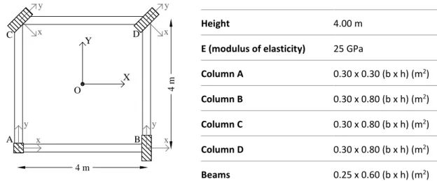
The first case study comprises a non-symmetric single storey structure. The plan view as well as the material and the geometrical characteristics of the structure are presented in Figure 3. Assumptions regarding the mechanical behaviour of the materials described in Section 2 are valid as well. The local structural axes of columns C and D are rotated -45o about the vertical
axis Z and all columns are considered fixed to the ground. This structure doesn’t correspond to a realistic building, but was chosen in order to represent a complex case study where the principal directions do not coincide with the main structural axes.
Following the procedure described in Section 3.2 the lateral stiffness matrix of the structure is determined in the global coordinate system O (X,Y,Z). Subsequently, the coordinates of the elastic centre CS, xCs = 0.6209 (m) and yCs = 1.3922 (m), and the angle ω = -31.58o that defines
the direction of principal axis I are determined in the same coordinate system. Next, the principal stiffness matrix is computed along with the coordinates of CS, x’K and y’K, with respect
to O and the rotated axes (
Figure 4a), as well as the coordinates of A, x’A and y’A, with respect to the principal reference
system CS (I, II, III) (
Figure 4b).
Height 4.00 m
E (modulus of elasticity) 25 GPa
Column A 0.30 x 0.30 (b x h) (m2)
Column B 0.30 x 0.80 (b x h) (m2)
Column C 0.30 x 0.80 (b x h) (m2)
Column D 0.30 x 0.80 (b x h) (m2)
Beams 0.25 x 0.60 (b x h) (m2)
Figure 3: Plan view and material and geometric characteristics of the single storey structure C A B O X Y x y x y 4 m 4 m D x y x y
By introducing the coordinates and the principal stiffness matrix coefficients into Eq. 8 the resultant displacement of the column corresponding to point A can be calculated for every value of α’. The derivative of the equation, solved with the mathematical software Maxima (Maxima 2014), leads to the ASIcrit with respect to the principal reference system α’crit = 182.3o.
The ASIcrit with respect to the X-Y reference system is determined from Eq. 9 equal to 150.7o.
(a) (b)
Figure 4: Determination of the CS (a) and A (b) coordinates
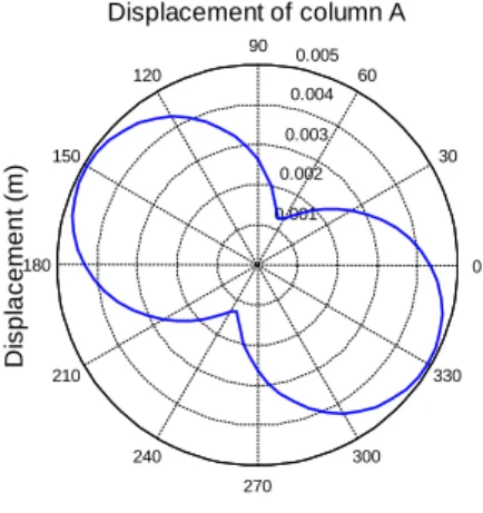
In order to verify the results obtained analytically, the structure is also simulated using the software OpenSees (McKenna et al. 2000) and a parametric analysis is performed by varying the ASI of a horizontal static load applied at the geometrical centre of the floor, O. The value of the force is assumed to be equal to 1kN and the ASI varies between 0o and 360o in steps of
0.5o. The variation of the displacement of point A with the ASI is shown in Figure 5. The
maximum displacement is achieved for an ASI equal to 150.5o, thus validating the analytical
result. It is noted that a further discretization of the angle step for the parametric analysis would lead to the exact same angle.
Figure 5: The displacement of column A due to the rotation of a unit static force
applied at O about the vertical axis Z
5.2. Multi-storey isotropic building
The second case study comprises a 3-storey isotropic building complying with the mechanical and material characteristics defined in Section 2. The plan view of a typical storey of the considered structure is presented in Figure 6a. The building consists of identical planar frames, shown in Figure 6b, which are connected at floor levels by rigid horizontal diaphragms. The height of all storeys is constant and equal to 3.50 m, the cross section dimensions of the
y'Cs =1. 51 m 4 m 4 m A O x y x'Cs =0. 2 m x y x y x y II I CS =31,58° CS y'A =4. 26 m 4 m 4 m A x'A =0. 45 m x y O x y x y x y II I =31,58° 0.001 0.002 0.003 0.004 0.005 30 210 60 240 90 270 120 300 150 330 180 0 Displacement of column A
Angle of incidence (degrees)
D is pl ac em ent ( m )
Since the vertical resisting elements have proportional stiffness matrices, the building is an isotropic building and has a real elastic axis and principal bending directions. The lateral stiffness matrix with respect to the global reference system (X,Y,Z) is given by:
O O O O O O O O O 3 K 0 K -6 K K= 0 K 4 K 5 K -6 K 5 K 249 K ⋅ ⋅ ⋅ ⋅ ⋅ ⋅ ⋅ ⋅ ⋅ (15) where K̲O is the following 3×3 lateral stiffness matrix of an individual frame:
O 55664.8 -32738.2 1769.6 K = -32738.2 61642.2 -30359.0 1769.6 -30359.0 288668.1 (16) The coordinates of the elastic axis, xCs = 1.25 m and yCs = 2.00 m, are calculated in the global
coordinate system (Figure 6a). The angle ω between the principal direction I and the global reference axis X is equal to zero since all resisting elements have their local structural axes parallel to the X or Y structural axes. The lateral stiffness matrix with respect to the principal bending planes defined by Eq. 14 is then:
O I,II,III O O 3 K 0 0 K = 0 4 K 0 0 0 230.75 K ⋅ ⋅ ⋅ (17) (a) (b)
Figure 6: Plan view of a typical floor of the 3-storey isotropic building (a) and typical frame (b)
(dimensions are in m)
Subsequently, the coordinates of point A, xA and yA, with respect to CS in the principal
coordinate system are calculated (see Figure 6a). Point A corresponds to the top of the column that has the maximum distance from the elastic axis in each floor, thus leading to the maximum displacement in each diaphragm.
By implementing Eq. 5 for systems having all their force resisting element axes parallel to the global axes, differentiating it with respect to α and solving the derivative equal to zero, the
ASIcrit leading to the maximum displacement is determined. The derivative and the equation
14.00 14.00 O I II yCs = 2.00 xCs = 1.25 xA = 6.25 1.00 3.00 3.00 2.00 2.00 X Y A CS 3.50 3.50 3.50 3.00 4.00 3.00 0.30×0.30 0.25×0.60
is solved with the Maxima software (Maxima 2014). The ASIcrit with respect to the principal
axes (I, II, III) is then found to be equal to 160.75o.
In order to verify the results obtained analytically, the structure is also simulated using the software OpenSees (McKenna et al. 2000) and a parametric analysis is performed by varying the ASI of a lateral distribution of horizontal static loads applied at the geometrical centres of the floor diaphragms. The value of the force at each diaphragm is assumed to be equal to 1 kN and the ASI varied between 0o and 360o in steps of 5o. It is noted that the lateral distribution
pattern of the horizontal forces only affects the magnitude of the displacements, not the ASIcrit, since the analysis is linear elastic and the building under consideration has a real elastic
axis. The maximum displacements of column A for each floor and the corresponding ASIcrit,
obtained using the Pythagorean Theorem, are determined and are presented in Figure 7. According to the parametric analysis, although the values of the maximum displacements for every storey are, as expected, different, the ASIcrit is found to be 160.0o for all storeys, thus
validating the value obtained from the analytical expression. The maximum displacement of the different diaphragms occurs under the same ASIcrit because of the isotropic properties of
the building. As noted for the previous example, a further discretization of the angle step for the parametric analysis would lead to the same angle obtained from the analytical expression.
Figure 7: The displacement of column A for each storey due to the rotation of a lateral
distribution of unit static force applied at the centres of mass of each diaphragm about the vertical axis Z
6. Concluding remarks
In the current paper an analytical framework was developed to determine the ASIcrit in single
storey buildings and multi-storey buildings with isotropic properties analysed with linear static analysis. Given that past research has shown that each demand parameter obtains its maximum value for a different ASI, the proposed approach only examined the storey displacements of the structure, including the top displacement, a demand parameter that was found suitable to describe global 3D structural performance. The validity of the developed framework was demonstrated by two case studies, a single storey building and a 3-storey isotropic building. The applicability of the proposed framework is straightforward since it depends only on the materials and the geometrical characteristics of the structure and it is independent of the external static force. An additional advantage of the methodology includes its validity for forces applied at any point of the diaphragm, thus allowing for the consideration of accidental eccentricities.
Although the presented framework introduces a direct methodology to determine the ASIcrit,
its applicability is still bounded by the requirement for constant lateral forces and the
2e-05 4e-05 6e-05 30 210 60 240 90 270 120 300 150 330 180 0
Displacement of column A, 1st storey
Angle of incidence (degrees)
D is pl ac em ent ( m ) 2e-05 4e-05 6e-05 8e-05 0.0001 30 210 60 240 90 270 120 300 150 330 180 0
Displacement of column A, 2nd storey
Angle of incidence (degrees)
D is pl ac em ent ( m ) 5e-05 0.0001 0.00015 30 210 60 240 90 270 120 300 150 330 180 0
Displacement of column A, 3rd storey
Angle of incidence (degrees)
D is pl ac em ent ( m )
existence of a real elastic axis. During LFA, the horizontal seismic forces may change in each direction depending on the response spectrum and the fundamental periods of vibration of the structure along the considered direction. As a result, the proposed methodology leads to accurate results in structures having their principal translational periods (periods that correspond to the principal directions) on the constant acceleration branch of the spectrum, in accordance with Morfidis et al. (2008). An extension of the methodology is currently being developed by the authors in which the shape of the response spectrum is introduced into the analytical expressions.
Regarding the existence of an elastic axis, it has been proven a prerequisite for the uncoupling of the dofs and thus the application of the methodology. However, in general multi storey buildings the nullification of the diaphragm rotations for translational excitation with horizontal static forces applied along a vertical axis is not possible. Since the elastic axis is a very good descriptor of a building and allows the determination of its static behaviour independently of the external loading (Makarios and Anastassiadis 1998), studies have been dedicated to extend and generalize its concept for general multi-storey buildings. Two different methodologies can be found in the literature that deal with the approximation of the elastic axis for multi-storey buildings (Makarios and Anastassiadis 1998; Marino and Rossi 2004; Doudoumis and Athanatopoulou 2008). The advancement of the proposed methodology with exploitation of these concepts constitutes an area of future research.
References
Anastassiadis, K. 1989. Antiseismic Structures. Volume I. Thessaloniki, Greece (In Greek): ZITI. Anastassiadis, K. 1985. “Caractéristiques élastiques spatiâles des bâtiments à étages”, Annales
de I’ I.T.B.T.P., No 435-Juin 1985
Athanatopoulou, A. M. 2005. “Critical Orientation of Three Correlated Seismic Components.”
Engineering Structures 27 (2): 301–12. DOI: 10.1016/j.engstruct.2004.10.011.
Athanatopoulou, A. M. and I. N. Doudoumis. 2008. “Principal Directions under Lateral Loading in Multistorey Asymmetric Buildings.” Structural Design of Tall and Special Buildings 17 (4): 773–94. DOI: 10.1002/tal.385.
Cantagallo, C., G. Camata, and E. Spacone. 2012. “The Effect of the Earthquake Incidence Angle on Seismic Demand of RC Structures.” In 15th World Conference on Earthquake Engineering. Lisbon, Portugal.
Doudoumis, I. N., and A. M. Athanatopoulou. 2008. “Invariant Torsion Properties of Multistorey Asymmetric Buildings.” Structural Design of Tall and Special Buildings 17 (1): 79–97. DOI: 10.1002/tal.320.
Fernandez-Davila, V. I., S. Cominetti, and E. F. Cruz. 2000. “Considering the Bi-Directional Effects and the Seismic Angle.” In 12th World Conference on Earthquake Engineering. Auckland, New Zealand.
Fernandez-Davila, V. I., and E. F. Cruz. 2008. “Estimating Inelastic Bi-Directional Seismic Response of Multi-Story Asymmetric Buildings Using a Set of Combination Rules.” In The 14th World Conference on Earthquake Engineering. Beijing, China.
Fontara, I. M., K. G. Kostinakis, G. E. Manoukas and A. M. Athanatopoulou. 2015. “Parameters Affecting the Seismic Response of Buildings under Bi-Directional Excitation.” Structural
Engineering and Mechanics 53 (5): 957–79. DOI: 10.12989/sem.2015.53.5.957.
Hosseini, M., and A. Salemi. 2008. “Studying the Effect of Earthquake Excitation Angle on the Internal Forces of Steel Building´s Elements by Using Nonlinear Time History Analyses.” In
14th World Conference on Earthquake Engineering. Beijing, China.
Kostinakis, K. G., , A. M. Athanatopoulou and V. S. Tsiggelis. 2013. “Effectiveness of Percentage Combination Rules for Maximum Response Calculation within the Context of Linear Time History Analysis.” Engineering Structures 56: 36–45. DOI: 10.1016/j.engstruct.2013.04.012. Lagaros, N. D. 2010. “Multicomponent Incremental Dynamic Analysis Considering Variable Incident Angle.” Structure and Infrastructure Engineering 6 (1-2): 77–94. DOI:
10.1080/15732470802663805.
Lopez, O. A., A. K. Chopra and J. J. Hernandez. 2000. “Critical Response of Structures to Multicomponent Earthquake Excitation.” Earthquake Engineering & Structural Dynamics 29 (12): 1759–78. DOI: 10.1002/1096-9845(200012)29:12<1759::AID-EQE984>3.0.CO;2-K. Lopez, O. A., A. K. Chopra and J. J. Hernandez. 2001. “Evaluation of Combination Rules for
Maximum Response Calculation in Multicomponent Seismic Analysis.” Earthquake
Engineering & Structural Dynamics 30 (9): 1379–98. DOI: 10.1002/eqe.68.
Lopez, O. A., and R.Torres. 1997. “The Critical Angle of Seismic Incidence and the Maximum Structural Responce.” Earthquake Engineering & Structural Dynamics 26 (9): 881–94. DOI:
10.1002/(SICI)1096-9845(199709)26:9<881::AID-EQE674>3.0.CO;2-R.
MacRae, G. A., and J. Mattheis. 2000. “Three-Dimentional Steel Building Response to near-Fault Motions.” Journal of Structural Engineering ASCE 126 (1): 117–126. DOI:
10.1061/(ASCE)0733-9445.
Magliulo, G., G. Maddaloni, & C. Petrone, 2014. “Influence of earthquake direction on the seismic response of irregular plan RC frame buildings.” Earthq. Eng. Eng. Vib. 13 (2): 243-256. DOI: 10.1007/s11803-014-0227-z.
Makarios, T. K., and K. Anastassiadis. 1998. “Real and Fictitious Elastic Axes of Multi-Storey Buildings: Theory.” Structural Design of Tall and Special Buildings 7 (1): 33–55. DOI:
10.1002/(SICI)1099-1794(199803)7:1<33::AID-TAL95>3.0.CO;2-D.
Marino, E. M., and P. P. Rossi. 2004. “Exact Evaluation of the Location of the Optimum Torsion Axis.” Structural Design of Tall and Special Buildings 13 (4): 277–90. DOI: 10.1002/tal.252. Maxima. 2014. “Maxima, a Computer Algebra System. Version 5.34.1.”
http://maxima.sourceforge.net/.
McKenna, F., G. L. Fenves, B. Jeremic and M. H. Scott. 2000. “Open System for Earthquake Engineering Simulation.” http://opensees.berkeley.edu/.
Menun, C. and A. Der Kiureghian. 2000. “Envelopes for Seismic Responce Vectors. II:
Application.” Journal of Structural Engineering 126(4): 474–81. DOI:
10.1061/(ASCE)0733-9445.
Menun, C. and A. Der Kiureghian. 1998. “A Replacement for the 30%, 40%, and SRSS Rules for
Multicomponent Seismic Analysis.” Earthquake Spectra. DOI: 10.1193/1.1586025.
Morfidis, K. E., A. M. Athanatopoulou and I. E. Avramidis. 2008. “Effects of Seismic Directivity within the Framework of the Lateral Force Procedure.” In 14th World Conference on Earthquake Engineering. Beijing, China.
Newmark, N. 1975. “Seismic Design Criteria for Structures and Facilities: Trans-Alaska Pipeline System.” In U.S. National Conference in Earthquake Engineering. Ann Arbor, Michigan. Quadri, S. A. and M. Madhurin. 2014. “Investigation of Critical Angle of Seismic Incidence for
the Analysis of RCC Frames.” In 12th IRF International Conference. Pune, India.
Riddel, R., and J. Vasquez. 1984. “Existence of Centers of Resistance and Torsional Uncoupling of Earthquake Response of Buildings.” In 8th World Conference on Earthquake Engineering,
187–94. San Francisco, USA.
Rosenblueth, E., and H. Contreras. 1977. “Approximate Design for Multi-Component Earthquakes.” Journal of the Engineering Mechanics Division 103(5): 895–911.
Roussopoulos, A. 1932. “Distribution of Horizontal Forces by a Rigid Plate in Spatial Structures: Case of Seismic Forces, Their Distribution and Regime.” Technika Chronika, Technical Chamber of Greece 17: 871–84 (In Greek).
Sebastiani, P. E., L. Liberatore, A. Lucchini and F. Mollaioli. 2014. “Simple Models to Predict the Most Critical Incedence Angle for Buildings under Bi-Directional near-Fault Excitations.” In 2nd European Conference on Earthquake Engineering and Seismology. Istambul, Turkey. Smeby, W., and A. Der Kiureghian. 1985. “Modal Combination Rules for Multicomponent Earthquake Excitation.” Earthquake Engineering & Structural Dynamics 13 (1): 1–12. DOI:
10.1002/eqe.4290130103.
Zaghlool, B. S., A. J. Carr, and P. J. Moss. 2001. “Inelastic Behaviour of Three-Dimensional Structures under Concurrent Seismic Excitations.” In 12th World Conference on Earthquake Engineering. Auckland, New Zealand.