OF
RADIATION SCIENCES
06-02 (2018) 01-14Accepted for publication: 2018-04-03
BJRS
Experimental verification of a methodology for Monte Carlo
modeling of multileaf collimators using the code Geant4
A. C. Holanda de Oliveira
a; J. W. Vieira
b; M. Zarza-Moreno
c; F. R. Andrade Lima
daDepartamento de Energia Nuclear, Universidade Federal de Pernambuco, 50670-901, Recife-PE, Brazil
bLaboratório de Dosimetria Numérica, Instituto Federal de Pernambuco, 50740-540, Recife-PE, Brazil
cDepartamento de Física, Universidade Nova de Lisboa, 1099-085, Lisboa, Portugal
dCentro Regional de Ciências Nucleares do Nordeste, 50740-545, Recife-PE, Brazil
ABSTRACT
Among the many algorithms developed for evaluation of dose distributions in radiotherapy, the Monte Carlo methods provide more realistic results. In intensity modulated radiation therapy, significant differences in dose distributions within the fields defined by multileaf collimator (MLC) could have significant radiobiology effects. Thus, it is important to model thoroughly the MLC to allow more accurate radiotherapy delivery. The objective of this work is to describe and to validate a methodology for modeling of MLCs using code Geant4. The Varian Millennium 120-leaf MLC was modeled using this methodology and it was experimentally verified. The leaves of the MLC were built using three types of solid (G4Box, G4Tubs and G4ExtrudeSolid) and the Boolean operation of subtraction (G4SubtractionSolid). Based on this methodology, it is possible to simulate other Varian MLC models and MLCs with similar design.
1. INTRODUCTION
Radiotherapy uses different techniques and equipment for treatment of cancer. The equipment most often used in radiotherapy is linear accelerator (Linac) which produces electron or X-ray beams in the energy range of 5 to 30 MeV (LOVEROCK, 2007). Among the many algorithms developed for evaluation of dose distributions of radiation, the simulations based on Monte Carlo (MC) methods provide more realistic results (VERHAEGEN, 2013). In intensity modulated radiation therapy (IMRT), where complex intensity distributions are delivered using a multileaf collimator (MLC), an accurate MC modeling of the Linac and MLC is very important. Significant differences in dose distributions of IMRT fields could have significant radiobiology effects (VERHAEGEN; SEUNTJENS, 2003).
MLC is composed of two banks of metal leaves that move perpendicularly to the radiation beam. The sides of the leaves are designed to have a kind of fit between them. This configuration is known as tongue-and-groove and has the objective to minimize the radiation transmitted between adjacent leaves (LOVEROCK, 2007). The dosimetric properties of MLC have to fulfill international standards and depend on its technical design specifications. The most important dosimetric parameters are leakage, penumbra and tongue-and-groove (T&G) effect. The leakage refers to radiation that emerges through the air gaps between adjacent leaves (IAG – interleaf air gap) and transmitted through the leaf material. Also, there is a small air gap (abutting leaf gap) between a completely closed leaf pair to avoid collision between opposing leaves. Penumbra is the region of rapid decrease at the radiation beam edges, commonly defined as the distance between the 20% and 80% isodose lines. The T&G effect occurs if transversally neighboring fields are irradiated (TACKE et. Al., 2006). Thus, it is important to model thoroughly the MLC to allow more accurate radiotherapy planning.
The objective of this work is to describe and to validate a methodology for MC modeling of MLCs using code Geant4 (AGOSTINELLI et al., 2003). To exemplify this methodology, the Varian Millennium 120-leaf MLC (Varian Oncology Systems, Palo Alto, CA) was modeled.
2. MATERIALS AND METHODS
In order to validate the modeling of the MLC, a 6 MV Varian Linac photon beam was also modeled. In this section, the methods and materials used for the simulations and the modelings on Geant4 (version 9.6), and the measurements for their experimental verifications are presented.
2.1 Varian Millennium 120-leaf MLC
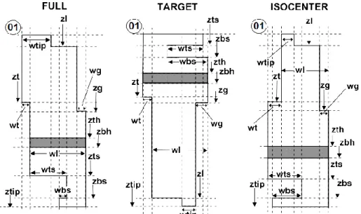
The Millenium MLC consists of 80 inner leaves (TARGET/ISOCENTER) and 40 outer leaves (FULL) whose width projects to 0.5 cm and 1.0 cm, respectively, at isocenter. A cross-sectional view of the inner and outer leaves is shown in Figure 1. Each leaf is separately driven by a motorized screw through a slit in the leaf (Figures 1 and 2, in gray). To account for the beam divergence and to minimize the geometric penumbra across the leaves, the leaf sides are focused towards the target (Figure 2a). Likewise, the leaf ends are rounded (Figure 2b) to maintain a fairly constant penumbra size as a function of the leaf position (HEATH; SEUNTJENS, 2003).
Figure 1: Cross sections of three leaf types of the Varian Millennium 120-leaf MLC, showing its
dimensions.
Figure 2: Cross sections and profile of leaves of the Varian Millennium 120-leaf MLC, showing
their inclination (a) and rounded ends (b).
(a) (b)
Source: Adapted from Rogers et. al. (2011).
The Varian Millenium 120-leaf MLC was firstly modeled by Heath and Seuntjens (2003) by using code BEAMnrc. Posteriorly, there have been some modifications of inputs and some bugs were fixed by the developers of BEAMnrc and the model of the MLC was named DYNVMLC (ROGERS et. al., 2011).
2.2 Monte Carlo Modeling of MLCs
The leaves of the MLC were built using three types of solid (G4Box, G4Tubs and G4ExtrudeSolid) and the Boolean operation of subtraction (G4SubtractionSolid).
The solid G4ExtrudeSolid was used to build the cross-sections of leaves, by defining vertex positions (x,y) relative to the center of the cross-sections. The first vertex (01) is the upper left of the leaf (Figure 1); the others follow this vertex in clockwise. The vertex x-values vary according to the leaf y-position (yleaf), such that the leaf left sides (Tongue-Side) are inclined at an angle θ0 and the leaf right sides (Groove-Side) are inclined at an angle θ1 (Figure 2a).
Tables 1, 2 and 3 show (in C ++) the positions of the fourteen vertices for each type of leaf, where A0 = θ0 and A1 = θ1, according to Equations 1 and 2:
θ0 = tg-1(y0 / (ZMLC - ZCENTER)) (1)
θ1 = tg-1 (y1 / (ZMLC - ZCENTER)) (2)
where ZCENTER is the distance from the leaf top to the MLC center (ZMLC).
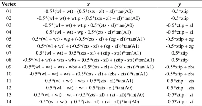
Table 1: Vertex positions of FULL leaf cross section of the Varian Millennium 120-leaf MLC.
Vertex x y
01 -0.5*(wl + wt) - (0.5*(zts - zl) + zl)*tan(A0) -0.5*ztip 02 -0.5*(wl + wt) + wtip - (0.5*(zts - zl) + zl)*tan(A0) -0.5*ztip 03 -0.5*(wl + wt) + wtip - 0.5*(zts - zl)*tan(A0) -0.5*ztip + zl 04 0.5*(wl + wt) - wg - 0.5*(zts - zl)*tan(A1) -0.5*ztip + zl 05 0.5*(wl + wt) - wg + (-0.5*(zts - zl) + (zg - zl))*tan(A1) -0.5*ztip + zg 06 0.5*(wl + wt) + (-0.5*(zts - zl) + (zg - zl))*tan(A1) -0.5*ztip + zg 07 0.5*(wl + wt) + (0.5*(zts - zl) + (ztip - zts))*tan(A1) 0.5*ztip 08 -0.5*(wl + wt) + wts - wbs + (0.5*(zts - zl) + (ztip - zts))*tan(A1) 0.5*ztip 09 -0.5*(wl + wt) + wts - wbs + (0.5*(zts - zl) + (zbs - zts))*tan(A1) -0.5*ztip + zbs 10 -0.5*(wl + wt) + wts + (0.5*(zts - zl) + (zbs - zts))*tan(A1) -0.5*ztip + zbs 11 -0.5*(wl + wt) + wts + 0.5*(zts - zl)*tan(A1) -0.5*ztip + zts 12 -0.5*(wl + wt) + wt + 0.5*(zts - zl)*tan(A0) -0.5*ztip + zts 13 -0.5*(wl + wt) + wt - (-0.5*(zts - zl) + (zt - zl))*tan(A0) -0.5*ztip + zt 14 -0.5*(wl + wt) - (-0.5*(zts - zl) + (zt - zl))*tan(A0) -0.5*ztip + zt
The ZCENTER values for each leaf type and the y0 and y1 values are given by Equations 3-7:
ZCENTER (FULL) = – 0.5ztip + zl + 0.5(zts – zl) (3) ZCENTER (TARGET) = – 0.5ztip + zbs + 0.5(zl – zbs) (4) ZCENTER (ISOCENTER) = – 0.5ztip + zl + 0.5(zts – zl) (5)
y0 = yleaf – 0.5(wl + wt) + 0.5wt – 0.5IAG (6)
Table 2: Vertex positions of TARGET leaf cross section of the Varian Millennium 120-leaf MLC. Vertex x y 01 -0.5*(wl + wt) - (0.5*(zl - zbs) + zbs)*tan(A0) -0.5*ztip 02 0.5*(wl + wt) - (0.5*(zl - zbs) + zbs)*tan(A1) -0.5*ztip 03 0.5*(wl + wt) - (0.5*(zl - zbs) + (zbs-zts))*tan(A1) -0.5*ztip + zts 04 0.5*(wl + wt) - wts - (0.5*(zl - zbs) + (zbs-zts))*tan(A1) -0.5*ztip + zts 05 0.5*(wl + wt) - wbs - 0.5*(zl - zbs)*tan(A1) -0.5*ztip + zbs 06 0.5*(wl + wt) - 0.5*(zl - zbs)*tan(A1) -0.5*ztip + zbs 07 0.5*(wl + wt) - (-0.5*(zl - zbs) + (zg-zbs))*tan(A1) -0.5*ztip + zg 08 0.5*(wl + wt) - wg - (-0.5*(zl - zbs) + (zg-zbs))*tan(A1) -0.5*ztip + zg 09 0.5*(wl + wt) - wg + (0.5*(zl - zbs) + (ztip-zl))*tan(A1) 0.5*ztip 10 0.5*(wl + wt) - wtip + (0.5*(zl - zbs) + (ztip-zl))*tan(A1) 0.5*ztip 11 0.5*(wl + wt) - wtip + 0.5*(zl - zbs)*tan(A1) -0.5*ztip + zl 12 -0.5*(wl + wt) + wt + 0.5*(zl - zbs)*tan(A0) -0.5*ztip + zl 13 -0.5*(wl + wt) + wt + (-0.5*(zl - zbs) + (zt-zbs))*tan(A0) -0.5*ztip + zt 14 -0.5*(wl + wt) + (-0.5*(zl - zbs) + (zt-zbs))*tan(A0) -0.5*ztip + zt
Table 3: Vertex positions of ISOCENTER leaf cross section of the Varian Millennium 120-leaf MLC.
Vertex x y
01 -0.5*(wl + wt) + wt - (0.5*(zts - zl) + zl)*tan(A0) -0.5*ztip 02 -0.5*(wl + wt) + wt + wtip - (0.5*(zts - zl) + zl)*tan(A0) -0.5*ztip 03 -0.5*(wl + wt) + wt + wtip - 0.5*(zts - zl)*tan(A0) -0.5*ztip + zl 04 0.5*(wl + wt) - wg - 0.5*(zts - zl)*tan(A1) -0.5*ztip + zl 05 0.5*(wl + wt) - wg + (-0.5*(zts - zl) + (zg - zl))*tan(A1) -0.5*ztip + zg 06 0.5*(wl + wt) + (-0.5*(zts - zl) + (zg - zl))*tan(A1) -0.5*ztip + zg 07 0.5*(wl + wt) + (0.5*(zts - zl) + (ztip - zts))*tan(A1) 0.5*tip 08 -0.5*(wl + wt) + (0.5*(zts - zl) + (ztip - zts))*tan(A1) 0.5*tip 09 -0.5*(wl + wt) + (0.5*(zts - zl) + (zbs - zts))*tan(A1) -0.5*ztip + zbs 10 -0.5*(wl + wt) + wbs + (0.5*(zts - zl) + (zbs - zts))*tan(A1) -0.5*ztip + zbs 11 -0.5*(wl + wt) + wbs + 0.5*(zts - zl)*tan(A1) -0.5*ztip + zts 12 -0.5*(wl + wt) + 0.5*(zts - zl)*tan(A0) -0.5*ztip + zts 13 -0.5*(wl + wt) + (-0.5*(zts - zl) + (zt - zl))*tan(A0) -0.5*ztip + zt 14 -0.5*(wl + wt) + wt + (-0.5*(zts - zl) + (zt - zl))*tan(A0) -0.5*ztip + zt
From the solid G4ExtrudeSolid is subtracted a parallelepiped (G4Box) referring to the driving screw hole, whose distance from the leaf edge is equal to HOLEPOS (Figure 2b). From the end of the resulting solid is subtracted a pipe section (G4Tubs) with internal radius equal to LEAFRADIUS.
A tungsten alloy with a composition of 90% tungsten, 6% nickel, 2.5% copper and 1.5% iron was used for the leaf material. The density and the IAG were chosen to match simulated dose distributions with experimental data.
2.3 Linac Model and Monte Carlo Simulations
The Linac and MLC modelings were performed according to the data kindly provided by Varian (https://myvarian.com/). The data for the Linac modeling are valid for the models TX, Trilogy, Clinac iX, DX, C/D, EX and cX.
The Linac model includes the target, primary collimator, vacuum exit window, flattening filter, monitor ion chamber, mirror and collimating jaws. The primary electron beam was defined by FWHM (full width at half maximum) values of energy and spatial Gaussian distributions, and the mean value of energy. These values were chosen to match simulated percentage depth dose (PDD) curves and lateral dose profiles with measured data. All simulations runs used the Geant4 Livermore physics model. The production threshold values were assigned for the target as 0.25 mm; for the flattening filter as 5.0 mm; for the primary and secondary collimators as 50.0 mm; for the MLC as 0.2 mm; and for the other structures as 1.0 mm. In Geant4, production threshold values are converted to cutoff energies for each material and for each particle type (i.e. electron, positron and gamma).
The simulations were divided in three parts: firstly a phase space above the secondary collimator was obtained; from this first phase space, phase spaces above the MLC, to validate the Linac modeling, and below the MLC were obtained; these secondary phase spaces were then provided as input to calculate the dose distributions in a water phantom.
In MC simulations for radiotherapy, phase spaces are files containing details (position, direction, energy, etc.) of the particles passing through a region. In this work, the phase spaces were generated in IAEA format (IAEA, 2006) using the writer class (G4IAEAphspWriter) developed by Cortés-Giraldo et. al. (2012), available at https://www-nds.iaea.org/phsp/Geant4/. In generation of the first phase space, 2×10⁹ primary electrons were emitted and bremsstrahlung splitting with a photon split factor of 10 was used in the target.
The water phantom was defined as a cube of 480×480×480 mm3. At runtime, the water cube is defined as sensitive volume (G4VSensitiveDetector) and is voxelized using the
G4VReadOutGeometry class. In the function ProcessHits, the energy deposited in the voxel where
the interaction occurred, its density and its coordinates are obtained. From the voxel volume, the dose is obtained and multiplied by the particle’s statistical weight. Then, the weighted dose and the voxel’s coordinates are passed to another class where the dose is added to the corresponding previous value. To estimate the uncertainty, at the end of each history (event), the square of dose is calculated and added to the previous value, and the total number of histories for each voxel is incremented (MA et. al., 2005). At the end of simulation, this information is recorded in a text file. To read the phase spaces, the functions of G4IAEAphspReader class were used (CORTÉS-GIRALDO et al., 2012).
2.4 Measurements
In order to validate the modelings, dose distributions in the water phantom were compared to experimental measurements.
In the case of Linac model, the data were a lateral dose profile at depth of 5 cm and a PDD curve for a field of 10×10 cm2. The measurements were performed in a Varian Clinac 2100C/D using a semiflex ionization chamber (PTW 31001) for the same conditions as the calculated ones. The active volume of this chamber is 0.125 cm3 and it has an inner diameter of 5.5 mm. The chamber was mounted on a computer controlled scanning system placed in an automatic water tank PTW FREIBURG (model 41006). Central axis depth ionization curves and transversal ionization profiles
were acquired using the PTW MEPHYSTO mc² software. For depth ionization curves the acquisition was made in steps of 0.1 cm up to 2 cm depth and 0.5 cm beyond 2 cm depth. Transversal profiles (X axis) were scored in steps of 0.25 cm in the central (homogeneous) region of field, being reduced to 0.1 cm for the acquisition of dose values in the penumbra and umbra region of the profiles.
For the verification of leakage, abutting leaf gap and T&G effect of the MLC, extended dose range (EDR) Kodak films were exposed in a solid water phantom at depth of 5 cm and source surface distance (SSD) of 95 cm. The films were properly developed with a regular film processor and then digitized using the VXR-16 film scanner by Vidar Company (Herndorn, VA). Subsequently, the images with a resolution of 0.0178 cm were analyzed using the RIT 113 Film Dosimetry software (Radiological Imaging Technology, Inc. Colorado, CO).
The leakage dose profile was generated perpendicular to the direction of the MLC leaf motion (Y axis) at a 3 cm offset from the central axis, using a field where all 60 leaf pairs were blocking the fields with the jaws collimator set to 10×10 cm2. Additional dose calculation for a 10×10 cm2 open field defined with the jaws and the leaves retracted was also carried out in a water phantom. Using these calculations, the percent leakage transmission through the MLC was determined by the ratio of the blocked field dose profiles to the on-axis dose value of the 10×10 cm2 open field.
In order to identify the optimal size of the abutting leaf gap, calculated and measured dose profiles were compared for a 10×10 cm2 field defined by jaws with the MLC leaves closed. The dose profile was obtained along the direction of leaf movement.
The impact of the T&G effect was investigated by creating a test field with alternating closed at the central axis and open leaves. This field was configured with the jaws set to produce a 10×10 cm2 field.
In order to verify the penumbra of the MLC, a lateral dose profile at depth of 5 cm and SSD of 95 cm was measured with a PinPoint ionization chamber (model PTW 31014) for a field of
10×10 cm2. The chamber has a 2 mm radius and a sensitive volume of 0.015 cm3 and it was mounted in a Wellhofer water scanning system. The profiles were adaptively step scanned at a depth of 5 cm using a minimum step of 0.1 cm. The effective point of measurement of this chamber was positioned at its geometric center according to the specifications of the chamber.
3. RESULTS AND DISCUSSION
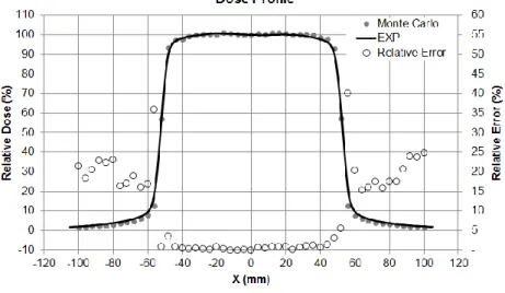
The comparison of PDD curves and dose profiles from experimental measurements and MC simulations for the Linac modeled are shown in the Figures 3 and 4, where the relative error is given point-to-point relative to experimental values. The average relative errors between the PDD curves in build-up region and beyond maximum dose region are 2.2% and 1.0%, respectively. The average relative errors between the dose profiles in penumbra-umbra region and high dose region (>80%) are 19.6% and 0.8%, respectively. These results are in agreement with the recommendations of TRS 30 of IAEA (2004). The mean energy value and energy and radial FWHM values used for the primary electron beam were, respectively, 6.2 MeV, 0.1 MeV and 0.1 mm.
Figure 3: Comparison of Percentage depth dose (PDD) curves for a field of 10x10 cm2 from
Figure 4: Comparison of lateral dose profiles (at depth of 5 cm) for a field of 10x10 cm2 from
experimental measurements (EXP) and Monte Carlo calculations for a 6 MV Linac model.
Figure 5 shows the comparison between dose profiles obtained experimentally and by MC simulation for verification of leakage, abutting leaf gap and T&G effect of the MLC modeled. A leaf material density of 17.35 g/cm3 was found to provide the best agreement between the measured and simulated leakage. The average interleaf leakage was 1.40% which is in agreement with the value measured using radiographic EDR films (1.42%). Comparing this experimental value with the simulated values for the different interleaf gap widths, it is observed that an interleaf gap of 0.06 mm gives the closest agreement between MC simulation and measurements, considering the uncertainty of 2% for MC simulations and 5% for film measurements. The experimental abutting leaf leakage was 27.23%. An abutting leaf gap of 0.04 mm provided the best agreement between the measured and simulated profile. It can be seen that the simulated dose profile for verification of T&G effect correctly predicts the pattern of the experimental dose profiles. The measured and simulated penumbra values were respectively 6.02 mm and 5.89 mm.
The leaf material density value in agreement with that found by Jang et. al (2006). The interleaf leakage and abutting leaf gap values are in agreement with that found by Heath and Seuntjens (2003). Okamoto et al (2014) also modeled the Varian Millennium 120-leaf MLC using Geant4, but they did not show the modeling methodology and this did not include the driving screw hole.
Figure 5: Dose profiles for verification of leakage (a), abutting leaf gap (b) and T&G effect (c) of the MLC modeled. (a) (b) (c)
4. CONCLUSION
In this work, it was described a methodology for MC modeling of MLCs using code Geant4. The Varian Millennium 120-leaf MLC was modeled using this methodology and it was experimentally verified. Using this methodology it is possible to simulate, besides Millennium 120-leaf MLCs, other Varian MLC models and MLCs with similar design. A 6 MV Varian Linac photon beam was
also modeled and validated. The results of the experimental validations of these modelings are in agreement with recommendations of international norms and with results of other authors. One of the perspectives of this work is the integration of these modelings with other in-house MC applications for dosimetric evaluations in radiotherapy.
REFERENCES
AGOSTINELLI, S.; et al. GEANT4 - A Simulation Toolkit. Nuclear Instruments and Methods in
Physics Research Section A, 506, 2003.
CORTÉS-GIRALDO, M. A.; QUESADA, J. M.; GALLARDO, M. I.; CAPOTE, R. An implementation to read and write IAEA phase-space files in GEANT4-based simulations.
International Journal of Radiation Biology, 88, 2012.
HEATH, E.; SEUNTJENS, J. Development and validation of a BEAMnrc component module for accurate Monte Carlo modelling of the Varian dynamic Millennium multileaf collimator. Physics in
Medicine and Biology, 48, 2003.
IAEA - INTERNATIONAL ATOMIC ENERGY AGENCY. Technical Reports Series No. 430:
Commissioning and Quality Assurance of Computerized Planning Systems for Radiation Treatment of Cancer. Vienna: IAEA, 2004.
IAEA - INTERNATIONAL ATOMIC ENERGY AGENCY. Phase-Space Database for External
Beam Radiotherapy. Vienna: IAEA, 2006.
JANG, S. Y.; VASSILIEV, O. N.; LIU, H. H.; MOHAN, R. Development and commissioning of a multileaf collimator model in Monte Carlo dose calculations for intensity-modulated radiation therapy. Medical Physics, 33, 3, 2006.
LOVEROCK, L. Linear Accelerators. In: MAYLES, P.; NAHUM, A.; ROSENWALD, J.C. (Org.).
Handbook of Radiotherapy Physics: Theory and Practice. Inglaterra: Taylor & Francis, 2007.
MA, C.-M.; LI, J. S.; JIANG, S. B.; PAWLICKI, T.; XIONG, W.; QIN, L. H.; YANG, J. Effect of statistical uncertainties on Monte Carlo treatment planning. Physics in Medicine and Biology, 50, 2005.
OKAMOTO, H.; FUJITA, Y.; SAKAMA, K.; SAITOH, H.; KANAI, T.; ITAMI, J.; KOHNO, T. Commissioning of 6 MV medical linac for dynamic MLC-based IMRT on Monte Carlo code Geant4. Radiological Physics and Technology, 7, 2, 2014.
ROGERS, D. W. O.; WALTERS, B.; KAWRAKOW, I. BEAMnrc Users Manual. Ottawa: National Research Council of Canada, 2011.
TACKE, M. B.; SZYMANOWSKI, H.; OELFKE, U.; SCHULZE, C.; NUSS, S.; WEHRWEIN, E.; LEIDENBERGER, S. Assessment of a new multileaf collimator concept using GEANT4 Monte Carlo simulations. Medical Physics, 33, 4, 2006.
VERHAEGEN, F.; SEUNTJENS, J. Monte Carlo modelling of external radiotherapy photon beams. Physics in Medicine and Biology, 48, 2003.
VERHAEGEN, F. Monte Carlo Modeling of External Photon Beams in Radiotherapy. In: SECO, J.; VERHAEGEN, F. (Eds). Monte Carlo Techniques in Radiation Therapy. USA: CRC Press, 2013.