RBCCV 44205-1498 DOI: 10.5935/1678-9741.20130076
Laser Doppler anemometry measurements of
steady low through two bi-lealet prosthetic heart
valves
Velocimetria laser de escoamento permanente através de duas próteses cardíacas de duplo folheto
Ovandir Bazan
1, Jayme Pinto Ortiz
1, Francisco Ubaldo Vieira Junior
2,3, Reinaldo Wilson Vieira
2,
Nilson Antunes
2, Fabio Bittencourt Dutra Tabacow
1, Eduardo Tavares Costa
3, Orlando Petrucci
Junior
21University of São Paulo (USP), Polytechnic School, Mechanical Engineer-ing Department, São Paulo, SP, Brazil.
2University of Campinas (UNICAMP), Department of Surgery, Medicine Center and Experimental Surgery, Campinas, SP, Brazil.
3University of Campinas (UNICAMP), Center for Biomedical Engineering, Campinas, SP, Brazil.
Hydrodynamic testing carried out at Department of Surgery, Medicine Cent-er and ExpCent-erimental SurgCent-ery,UnivCent-ersity of Campinas (UNICAMP), Campi -nas, SP, Brazil.
Work paper carried out at Departamento de Engenharia Mecânica da Escola Politécnica da Universidade de São Paulo (PME-PUSP), São Paulo, SP, Brazil.
No inancial support. Correspondence address: Ovandir Bazan
Av. Prof. Mello de Moraes, 2231 – Cidade Universitária Armando de Salles Oliveira – São Paulo, SP, Brazil – Zip code: 05508-030
E-mail: [email protected]
Article received on April 4th, 2013 Article accepted on September 16th, 2013
Abstract
Introduction: In vitro hydrodynamic characterization of prosthetic heart valves provides important information regarding their operation, especially if performed by
noninvasive techniques of anemometry. Once velocity proiles
for each valve are provided, it is possible to compare them in
terms of hydrodynamic performance. In this irst experimental
study using laser doppler anemometry with mechanical valves,
the simulations were performed at a steady low workbench.
Objective: To compare unidimensional velocity proiles at
the central plane of two bi-lealet aortic prosthesis from St. Jude (AGN 21 – 751 and 21 AJ – 501 models) exposed to a steady low regime, on four distinct sections, three downstream and
one upstream.
Methods: To provide similar conditions for the low through
each prosthesis by a steady low workbench (water, low rate of 17L/min.) and, for the same sections and sweeps, to obtain the velocity proiles of each heart valve by unidimensional
measurements.
Results: It was found that higher velocities correspond to the prosthesis with smaller inner diameter and instabilities of
low are larger as the section of interest is closer to the valve. Regions of recirculation, stagnation of low, low pressure, and low peak velocities were also found.
Conclusions: Considering the hydrodynamic aspect and for every section measured, it could be concluded that the prosthesis
model AGN 21 - 751 (RegentTM) is superior to the 21 AJ – 501 model (Master Series). Based on the results, future studies can choose to focus on speciic regions of the these valves.
Descriptors: Heart valve prosthesis. Blood low velocity.
Laser-Doppler lowmetry.
Resumo
Introdução: A caracterização hidrodinâmica in vitro de pró-teses de válvulas cardíacas fornece informações importantes quanto ao seu funcionamento, sobretudo se realizada por meio de métodos não-invasivos de anemometria. Uma vez obtidos os
peris de velocidade para cada válvula, é possível compará-las
quanto ao seu desempenho hidrodinâmico. Neste primeiro
METHODS
The objective of this study was to compare, during a steady low regime, the velocity proiles at the central plane of two St. Jude bi-lealet aortic valves. For this reason, it was necessary to establish a suitable methodology for experimental hydrodynamic testing. An academic agreement celebrated between EPUSP and UNICAMP made it possible to use the 1D LDA system, the steady low hydrodynamic workbench, and the valve prostheses.
The in vitro simulations presented in this paper did not have the purpose of reproducing the physiological conditions of the test luid (blood analog properties of viscosity, density, and temperature), neither mimicking the physiological pressure and volumetric low curves. The test luid used was water at 27ºC and a steady low condition was imposed in order to compare the velocity proiles of the two prostheses under the same range of volumetric discharge. In order to meet the speciic purpose of this study (velocity proiles comparison), the ISO 5840:2005 guidelines [11] were not considered for the hydrodynamic performance analysis in steady low regime (i.e., the imposition of volumetric low discharge from 5 to 30 L/min., varying every 5 L/min.), although the unique imposed low rate was close to the mean value established in those guidelines. Similarly, the question of the “effective oriice area” of the prostheses, discussed in the standard as criteria for the hydrodynamic performance analysis, was not addressed here. These characteristics, as well as pulsatile testing, are convenient and will be the target of next studies [13,14].
The materials and methods used in this study are presented below.
INTRODUCTION
In vitro hydrodynamic characterization of prosthetic heart valves provides important information regarding their operation [1,2], especially if performed by noninvasive techniques of anemometry [3-8]. Regarding hydrodynamic performance, it is possible to compare the velocity proiles for each valve and develop new designs. Velocity proiles are different for every type of valve and regions of low
stagnation and separation could occur, inducing formation of
thrombosis, tissue overgrowth and/or calciication as well as blood hemolysis due to shear stress [1,9,10]. ISO 5840:2005 standard offers a pattern for the hydrodynamic performance testing of prosthetic valves, considering a steady or pulsatile low and allowing for the evaluation of these valves [11,12].
Nevertheless, the comparison between prosthetic heart valves is possible under some conditions of low similarity, which is the speciic objective of this study: to compare the velocity proiles of two St. Jude bi-lealet aortic valves with a nominal diameter of 21 mm exposed to a steady low regime. The 1D velocity proiles were obtained at the central plane of low, on four distinct sections, three downstream and one upstream of the valves.
This irst experimental study is due to an academic agreement established between UNICAMP (Medical School, Department of Surgery) and EPUSP (Polytechnic School, Mechanical Engineering Department). The study was developed at the Medicine Center and Experimental Surgery and the Biomedical and Environmental Engineering Laboratory, from the Medical School (UNICAMP) and Polytechnic School (EPUSP), respectively.
Abbreviations, acronyms & symbols
1D Unidimensional 2D Bidimensional 3D Tridimensional
LDA Laser Doppler anemometer
as simulações foram realizadas em bancada de testes para es-coamento permanente.
Objetivo: Comparar peris de velocidade unidimensional no
plano central de duas próteses aórticas de duplo folheto St. Jude (modelos AGN 21 – 751 e 21 AJ – 501) submetidas a um regime de luxo permanente, para quatro seções distintas, três à jusante e uma à montante.
Métodos: Proporcionar condições de similaridade para o es-coamento através de cada prótese, por meio de bancada
hidro-dinâmica para escoamento permanente (água, à vazão de 17 L/ min.) e, por meio de anemometria laser unidimensional, obter os peris de velocidades para as mesmas seções e varreduras.
Resultados: Veriicou-se que as maiores velocidades corres
-pondem à prótese de diâmetro interno menor e que as instabi
-lidades do luxo são maiores à medida que a seção de interesse encontra-se mais próxima da válvula. Também foram veriica
-das as regiões de recirculação, de estagnação do luxo e de baixa
pressão, além dos picos de velocidade para o escoamento em questão.
Conclusões: Sob o aspecto hidrodinâmico e para todas as
seções de interesse, foi possível concluir a preferência da válvula
de modelo AGN 21 - 751 (RegentTM) sobre a 21 AJ – 501 (Master
Series). Os resultados obtidos permitiram escolher, para os pró
-ximos trabalhos, um foco de estudo mais especíico para regiões
concretas dessas próteses.
Descritores: Próteses valvulares cardíacas. Velocidade do
Hydrodynamic workbench for steady low regime
The experimental workbench for the hydrodynamic testing in steady low regime was designed at the Biomedical and Environmental Engineering Laboratory of EPUSP and was adapted at the Medicine Center and Experimental Surgery of UNICAMP.
The workbench (Figure 1) consists of two reservoirs, an acrylic test chamber, sealing rings, three spherical valves,
connections and pipes in PVC, and a positive displacement
hydraulic pump with a nominal low discharge of 360 gallons per hour (22.71 L/min). The same low discharge was imposed for each experiment, allowing for the comparison of the velocity proiles obtained from the valves. An indirect method of volumetric low measurement was used, by determining the effective low of the pump once the steady state regime was performed on the hydrodynamic workbench.
The effective pump low discharge was obtained through variations in observed volume in a chamber of the experimental workbench during a certain period of time measured by a chronometer. With the experimental workbench adjusted for steady low and with the hydraulic circuit to the testing chamber blocked (changing the valve in Figure 1, n.1, to the closed position), the illing up of the superior reservoir up to a stipulated height for a registered period of time was observed. The water volume was determined through the internal area of the base of the superior reservoir. The effective pump low discharge was obtained dividing this volume by the measured time.
The steady low regime was performed when the water level in the reservoirs remained invariable. The same low resistance in the hydraulic circuit (equivalent resistance) was
established for each experiment. Considering the differences between the two cardiac prostheses used, they offer distinct resistances to low circulation, which implies different pressure distributions for each one (see the Results section). The equivalent low resistance (total head loss) for each experiment was ensured by regulating the inferior spherical valve of the hydrodynamic workbench (Figure 1, n. 2). This spherical valve implies an adjustable low resistance to the hydraulic circuit. To validate each experiment, the other two spherical valves (Figure 1, n. 1 and n. 3) remained , fully open and fully closed, respectively. In addition, the same total water volume was ensured on every testing. The effective low value can be seen in the results section.
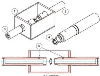
In order to use the LDA system, a test chamber was conceived in a speciic region of the hydraulic circuit (Figure 1, Detail A). The design of this test chamber is shown in Figure 2. It consists of two pipes and an optical coninement (Figure 2, n. 1), both in acrylic, and seal rings. The prosthesis (Figure 2, n. 4) is positioned under pressure, by longitudinal assembling of the two pipes, which in turn slide within the test chamber oriices. The two pipes downstream and upstream of the prosthesis (respectively, n. 2 and n. 3 in Figure 2) have internal diameters of 21.20 mm (able to shelter the chosen prosthesis) and both pipes are 210 mm long (upstream pipe length allows for the developed low to be measured; downstream pipe length offers LDA measurements on different sections). Each pipe has one oriice to acquire pressure (Figure 2, n. 5) based on the height of the water column so that differential pressure can be obtained. When the pipes are positioned, they lock the prosthesis inside them. In this condition, the oriices are located 40 mm upstream and 20 mm downstream of the prosthesis.
Fig. 1 - Steady low hydrodynamic workbench photo
Highlighted: A (test chamber), 1 (top spherical valve), 2 (bottom spherical valve) and 3 (maintenance spherical valve)
Fig. 2 - Workbench test chamber detail
Prostheses used
The high frequency of valve replacement in the aortic position gave support to the choice of these prosthesis models in the research here presented [15-16].
Two St. Jude bi-lealet prosthetic aortic valves, models 21
AGN – 751 (RegentTM) and 21 AJ – 501 (Masters Series), [17]
were used. Although the two valves have the same nominal diameter of 21 mm, they have internal diameters of 19.6 mm and 16.7 mm, respectively. These prostheses models are shown in Figure 3.
Considering dimensional variations of mechanical valves are negligible, only one prosthesis of each model was used in this study. So the results were considered independent of the number of samples. On the other hand, the internal diameter difference of the two prostheses (two different models) enabled the comparison and discussion of the results. Further studies are necessary to properly deine the number of samples (prostheses).
volume at a particular intersection point. Since it is usually
possible to separate three laser-beam wavelengths (violet, blue, and green) generated by the source, each wavelength can be manipulated in pairs of beams in orthogonal planes and it can provide information on up to three velocity components simultaneously: in each plane and for a speciic point. This is why LDA systems are suitable for accurate velocity measurements. The most well-known coniguration is called backscattering. In this coniguration, the probes perform two simultaneous functions. Firstly, they are responsible for the convergence of monochromatic pairs of laser beams into the measurement point (intersection volume) through the outer lens (focusing lens). Secondly, they receive the scattered light (from seeding particles) through the inner lens (reception phase).
When crossing the measurement volume, the seeding particles (contained in the low) induce the scattering of light in varying intensity according to the low velocity at that point. This returning light is redirected to the detection, signal conditioning, and processing phases. Finally, the results of the processing phase are manipulated and displayed using speciic software. Thus, it is possible to know the velocity components of low (1D, 2D, or 3D, depending on the system coniguration) through sweeping points comprised of a linear sequence of measurement volumes.
In this study, the LDA system of the Laboratory of Surgical Technique and Experimental Surgery at UNICAMP was used. The equipment is from Dantec Dynamics and it is actually capable of 1D velocimetry measurements only. This LDA system is based on Argon ions laser (Innova 70 Coherent, nominal power of 4 W), which is refrigerated by air with a backscattering coniguration. The BSA Flow Software, from the same company, was also used.
The scope of this study was the use of the 1D LDA system in order to obtain information about the horizontal plane of the low. In addition, a manual traverse system was used for positioning the probe and, consequently, scanning the observed measurement points upstream and downstream of the prostheses.
RESULTS
The 1D measurement results (one section upstream and three sections downstream of the valves) obtained for the two St. Jude bi-lealet prosthetic aortic valves through a steady low are presented. Introductorily, the low conditions, which were derived from the operating workbench, as well as the proper positioning of the LDA probe, are presented below.
Preliminary preparation
The prostheses were arranged in the test chamber as described in the methodology. The test luid used was water at 27°C, with the addition of seeding particles of 20 μm in Fig. 3 - Aortic bi-lealet prosthetic heart valves used
Highlighted: from left to right, models 21 AGN - 751 and 21 AJ - 501
LDA used: working principle and description
Before describing the LDA system used, its working principle is briely discussed.
The laser Doppler anemometry system (or LDA) consists of a irst stage of laser beam transmission so that pairs of laser beams converge into an intersection point, representing the point of interest to be measured (low containing seeding particles). At the same time, another stage occurs, which is characterized by the detection of scattered light radiation from the small intersection volume (when particle motion is due to speciic low velocities). Then, these data can be conditioned and processed for a particular type of information, since the lashing light frequency (Doppler frequency) is proportional to the low velocity at the measurement point.
diameter (Dantec Dynamics, Polyamide Seeding Particles).
Plastic hoses were conveniently connected with a manometer in order to acquire differential pressure from the pipes’ oriices upstream and downstream of the prosthesis
(Figure 2, n. 5).
As mentioned in the methods section, the low used in the test chamber was the pump’s effective low, once both the same volume of water on the workbench and the steady low regime on each experiment was established. The volumetric low discharge was obtained indirectly: volume variation over measured time. This procedure was repeated three times and an arithmetic average was obtained. It was found that the low rate imposed on the prosthesis was approximately 17 L/min. and this value represents the only possible low discharge for the test chamber.
With the LDA system in operation, the manual traverse system was referenced so that the laser beams always reached the mean horizontal plane of the pipes. A controlled routine established, via software, for the operation of the LDA system allowed some variables of the spectral analyzer to be controlled during the experiments, such as: the acquisition rate (up to 10 KHz), the photomultiplier voltage (up to 1,000 V), the ampliier signal gain (35 dB), and the operating power (170 mW). As described in the methods section, the LDA system operated only as 1D, through a probe with a pair of laser beams for the green spectrum and with the following characteristics: wavelength (ƛ) of 514.5 nm, diameter of 1.35 mm, focal length of 160 mm, spacing of the laser beam pair in the focal lens (frontals) of 38 mm, and fringes spacing (at the intersection volume of the beans) of 2.182 μm, with a
total of 35 fringes.
After establishing the horizontal plane for the reference position, the probe was positioned in the sections and points of interest, as shown in Figure 4.
Following the low direction, the irst point of interest was
at 30 mm before the prosthesis (Figure 4, upstream). Three other points of interest were located after the prosthesis at 8 mm (Figure 4, downstream 1), 20 mm (Figure 4, downstream 2), and 32 mm (Figure 4, downstream 3). Therefore, the 1D
LDA measurements consisted of scans of four sections for
each prosthesis: one upstream and three downstream of the
valve.
Measurements in the hydrodynamic workbench
After each prosthesis was assembled in the test chamber (Figure 2), the steady low was established, and the probe was conveniently positioned facing the measurement point (Figure 4), the LDA system was used to obtain the 1D velocity proiles at the central plane along the inner diameter of the pipes (21.20 mm) and for four sections along low direction. Every new measurement at the point of interest was obtained by displacing the LDA probe longitudinally through 0.50 mm over the horizontal diameter plane.
Under 17L/min. of low discharge, differential pressure was 42 mm of water column (or 3.09 mmHg) for assembling the prosthesis 21 AGN - 751 (internal diameter of 19.6 mm) and 63 mm of water column (or 4.63 mmHg) for the prosthesis 21 AJ - 501 (internal diameter of 16.7 mm).
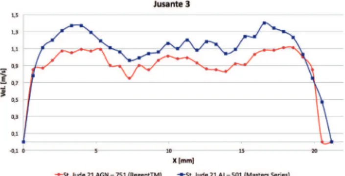
Figures 5 to 8 show the measured velocity proiles for the two prosthetic valve models, under steady low conditions with a volumetric discharge of 17 L/min, for each point of interest. The discussion of the results is presented in the next section.
Fig. 4 - Measurement sections referenced at the prosthesis positioning Highlighted: in the low direction, upstream at 30 mm, downstream 1 at 8 mm, downstream 2 at 20 mm and downstream 3 at 32 mm from the valve
Fig. 5 - Velocity proiles at 30 mm upstream of the valves
DISCUSSION
Fig. 6 - Velocity proiles at 8 mm downstream of the valves
Fig. 7 - Velocity proiles at 20 mm downstream of the valves
Fig. 8 - Velocity proiles at 32 mm downstream of the valves
low restrictions in the passage of the low, which implies different localized head loss. According to the literature, a prosthesis with larger diameter offers a smaller head loss. To ensure that in each of the experiments the same equivalent resistance was imposed on the hydraulic circuit, we used a spherical valve (Figure 1, n. 2). In fact, when the prosthesis with smaller diameter was used, this speciic spherical valve was kept more open.
Each velocity proile obtained at 30 mm upstream the valve allowed for the low discharge to be estimated by integrating the velocity proile in the referenced area. This calculation conirms the previously measured value of 17 L/ min. with an error margin of approximately 5%. However, the testing by means of this single low discharge represents an intrinsic limitation of this study [18].
The results obtained using the 1D LDA correspond to those expected from the literature: for all of the downstream measurement sections, greater velocities correspond to the prosthesis with a smaller internal diameter (16.7 mm, St. Jude model 21 AJ – 501), with higher transversal gradients near the pipe wall. In terms of pressure measurements, the prosthesis with a larger internal diameter (19.6 mm, St. Jude model 21
AGN – 751) presented smaller values of differential pressure
and, consequently, smaller local head loss (42 mm of water column, or 3.09 mmHg). This implies smaller resistance to the passage of low, compared with the prosthesis with a smaller diameter. In terms of low instabilities downstream the prosthesis, it was observed that they are greater in the section near the prosthesis (section 1, downstream). It was found that although certain symmetry of the velocity proiles occurs, this symmetry is not signiicant.
Some small negative values of velocity were measured with the LDA system. Recirculation zones were observed for both prosthesis models, St. Jude 21 AGN – 751 and St. Jude 21 AJ – 501, particularly in the downstream sections. Although negative values of velocity were expected in the prostheses surroundings, they were not expected at the farthest sections (downstream 2 and 3). The transversal gradients of velocity are much more pronounced in the case of the prosthetic valve with a larger diameter (St. Jude 21 AJ – 501), which is possible to observe by analyzing Figures 6 and 7. Similar future studies with measurements in more than one direction, i. e., 2D LDA measurements, will be used to validate the results obtained in this study.
In terms of hydrodynamics, the prosthesis with a larger internal diameter should be adopted, considering the smaller peak velocities in the aortic root and the smaller transversal velocity gradients in this case, with less probability of recirculation. This is in accordance with the adequate sizing of the effective oriice area criteria so that residual stenosis after valve implantation can be avoided, thereby minimizing the occurrence of elevated pressure gradients through the valve [19]. On the other hand, the occurrence of
REFERENCES
1. Yoganathan AP, He Z, Casey Jones S. Fluid mechanics of heart
valves. Ann Rev Biomed Eng. 2004;6:331-62.
2. Dasi LP, Simon HA, Sucosky P, Yoganathan AP. Fluid mechanics of artificial heart valves. Clin Exp Pharmacol Physiol. 2009;36(2):225-37.
3. Chew YT, Chew TC, Low HT, Lim WL. Techniques in the determination of the flow effectiveness of prosthetic heart valves. In: Cardiovascular techniques: biomechanical systems: techniques and applications. vol. II. London:Cornelius Leondes, CRC Press LLC;2001. p.70-117.
4. Yoganathan AP, Chandran KB, Sotiropoulus F. Flow in prosthetic heart valves: state-of-the-art and future directions. Ann Biomed Eng. 2005;33(12):1689-94.
This can be seen for the two St. Jude prostheses tested here. The AGN 21 - 751 (RegentTM) model is designed for
supra-annular suture and the AJ 21 - 501 (Masters Series) model for intra-annular suture. Currently, due to hemodynamic advantages, most surgeons employ the supra-annular positioning, even if there is a discrepancy among manufacturers regarding different internal diameter of the prostheses based on valves with the same nominal diameter [20-22]. For the prostheses studied here, which are from the same manufacturer, the choice of supra-annular prosthesis implies a valve with a larger inner diameter, although the two models have the same
nominal diameter (21 mm). In fact, smaller peak velocities
and a better hydrodynamic behavior were observed for all measurements of the supra-annular prosthesis 21 AGN – 751 (RegentTM) points of interest (Figures 6 to 8). However, it is not possible to disregard some surgical priorities that can be more relevant in some cases than the hydrodynamic aspects for a certain group of patients [20].
Clearly, the present study has some limitations because it does not include other low ranges besides 17 L / min. [11, 18] and the LDA system available is restricted to 1D measurements. It would be feasible to extend this study by using another type of pump and including additional spherical valves and a lowmeter in the hydrodynamic circuit, so that it is possible to adjust other values of volumetric discharge in steady low regime. As explained in the methodology, this will be the focus of the next study, using a cardiac simulator (USP), where 2D laser anemometry will be used for velocity measurements [13,14].
CONCLUSION
For the two prosthetic valves tested according the hydrodynamic aspect considered, it was possible to verify the superiority of the prosthesis model AGN 21 - 751 (RegentTM)
comparing with model 21 AJ – 501 (Master Series). This choice implies the supra-annular positioning. The results permit to focus, in next work, the observations and measurements in some speciic regions nearby the prosthesis were the low recirculation and peak velocities occurs. According with was exposed in methods, for further testing will be possible include a statistical analysis based on a batch of valves and regarding some guidelines suggested by the ISO 5840:2005 standard.
ACKNOWLEDGEMENTS
This research had the support of: Faculdade de Medicina da UNICAMP, through Laboratório de Técnica Cirúrgica e
Cirurgia Experimental, Escola Politécnica da USP (EPUSP),
through Laboratório de Engenharia Ambiental e Biomédica (PME, LAB), and Centro Tecnológico de Hidráulica (CTH). The authors are grateful to these institutions for the infrastructure support during the research development.
The authors also are grateful to Coordenação de Aperfeiçoamento de Pessoal de Nível Superior (CAPES)
for the doctorate scholarship linked to the Programa de Pós-Graduação em Engenharia Mecânica of EPUSP.
Author’s roles & responsibilities
OB LDA equipment maintenance estimating; steady workbench design and manufacturing (except the test section of the prosthesis), test section CAD re-drafting; transfering and assembling of hydrodynamic workbench between USP and Unicamp; LDA training; LDA testing with the prostheses; paper writing, igures, graphs and resion; revisor replicas.
JPO: Academic partnership coordinator and linked jobs between USP and UNICAMP, LDA trials monitoring; line of research guiding at USP; paper revision and revisor replicas.
FUVJ: Workbench test section CAD drawings; test section
manufacturing; LDA training; LDA testing with the prostheses; paper revision.
RWV: Academic partnership coordinator and linked jobs between USP and UNICAMP, LDA trials monitoring; line of research guiding at Unicamp; paper review.
NA: Responsible for resources inding, maintenance and re-structuring of Medicine Center and Experimental Surgery Laboratory (LDA system); responsible for the heart valves obtainning from St. Jude Medical Brazil.
FDBT: Transfering and assembling of hydrodynamic workbench between USP and Unicamp; LDA training; LDA testing with the prostheses; testing photos.
ETC: Responsible for the workbench test section building (by the Center for Biomedical Engineering, CEB, Unicamp ) and enable the maintaining resources of the LDA equipment via CEB. OPJ: Responsible for the Cardiac Surgery discipline at Unicamp and
5. Grigioni M, Daniele C, D’Avenio G, Morbiducci U, Del Gaudio
C, Abbate M, et al. Innovative technologies for the assessment
of cardiovascular medical devices: state-of-the-art techniques for artificial heart valve testing. Expert Rev Med Devices. 2004;1(1):81-93.
6. Meyer RS, Deutsch S, Bachmann CB, Tarbell JM. Laser Doppler velocimetry and low visualization studies in the regurgitant leakage low region of three mechanical mitral valves. Artif Organs. 2001;25(4):292-9.
7. Pinotti M. Is there correlation between the turbulent eddies size and mechanical hemolysis? J Braz Soc Mech Sci. 2000;22(4). Available from: URL: http://www.scielo.br/scielo. php?script=sci_arttext&pid=S0100-73862000000400006.
8. Meyer RS, Deutsch S, Maymir JC, Geselowitz DB, Tarbell JM. Three-component laser Doppler velocimetry measurements in the regurgitant low region of a Björk-Shiley monostrut mitral valve. Ann Biomed Eng. 1997;25(6):1081-91.
9. Lu PC, Lai HC, Liu JS. A reevaluation and discussion on the threshold limit for hemolysis in a turbulent shear low. J Biomech. 2001;34(10):1361-4.
10. Woo YR, Yoganathan AP. Pulsatile low velocity and shear stress measurements on the St. Jude bilealet valve prosthesis. Scand J Thorac Cardiovasc Surg. 1986;20(1):15-28.
11. American National Standard. Cardiovascular implants – cardiac valve prostheses, ISO 5840:2005.
12. Cheade EL. Atualização de sistema duplicador de pulsos para teste de válvulas cardíacas [Dissertação de Mestrado]. Campinas: UNICAMP, Faculdade de Engenharia Elétrica e de Computação; 2008. 120p.
13. Bazan O, Ortiz JP. Design conception and experimental setup for in vitro evaluation of mitral prosthetic valves. Rev Bras Cir Cardiovasc. 2011;26(2):197-204.
14. Bazan O, Ortiz JP. Sistema duplicador de pulsos para análise
in vitro de próteses de válvulas cardíacas – testes preliminares de validação, em: 7º Congresso Latino Americano de Órgãos Artiiciais e Biomateriais, COLAOB 2012, 2012, Natal/ RN, Proceedings of COLAOB 2012, disponível em: www.metallum. com.br/7colaob/resumos/trabalhos_completos/02-015.docx.
15. De Paulis R, Schmitz C, Scaffa R, Nardi P, Chiariello L, Reul H. In vitro evaluation of aortic valve prosthesis in a novel valved conduit with pseudosinuses of Valsalva. J Thorac Cardiovasc Surg. 2005;130(4):1016-21.
16. Dasi LP, Ge L, Simon HA, SotiropouloS F, Yoganathan AP. Vorticity dynamics of a bilealet mechanical heart valve in an axisymmetric aorta. Phys Fluids. 2007;19(6):067105-17.
17. St. Jude Medical, Cardiac Surgery, U.S. Product Catalog, April 2010.
18. Blais C, Pibarot P, Dumesnil JG, Garcia D, Chen D, Durand
L-G. Comparison of valve resistance with effective oriice area
regarding low dependence. Am J Cardiol. 2001;88(1):45-52.
19. Dotta, F, Torres M, Manfroi W, Guaragna JCVC, Caramoni P, Albuquerque LC, et al. Desproporção prótese aórtica-paciente: definição, impacto e prevenção, Rev Bras Ecocardiogr. 2007;20(4):34-8.
20. Zhang M, Wu QC. Intra-supra annular aortic valve and complete supra annular aortic valve: a literature review and hemodynamic
comparison. Scand J Surg. 2010;99(1):28-31.
21. Seitelberger R, Bialy J, Gottardi R, Seebacher G, Moidl R, Mittelöck M, et al. Relation between size of prosthesis and valve gradient: comparison of two aortic bioprosthesis. Eur J Cardiothorac Surg. 2004;25(3):358-63.
22. Guenzinger R, Eichinger WB, Hettich I, Bleiziffer S, Ruzicka D, Bauernschimitt R, et al. A prospective randomized comparison of the Medtronic Advantage Supra and St Jude Medical Regent mechanical heart valves in the aortic position: is there an
additional beneit of supra-annular valve positioning? J Thorac