ISSN 1549-3636
© 2007 Science Publications
Corresponding Author: Adel Alti, Department of Computer Science, Farhat Abbes University of Setif, Algeria 793
Integrating Software Architecture Concepts into the MDA
Platform with UML Profile
1
Adel Alti,
2Tahar Khammaci and
2Adel Smeda
1Department of Computer Science, Farhat Abbes University of Setif, Algeria
2LINA, Université de Nantes, 2, Rue de la Houssinière, 44322, Nantes, France
Abstract: Architecture Description Languages (ADLs) provide an abstract representation of software systems. Achieving a concrete mapping of such representation into the implementation is one of the principal aspects of MDA (Model Driven Architecture). Integration of ADLs within MDA confers to the MDA platform a higher level of abstraction and a degree of reuse of ADLs. Indeed they have significantly different platform metamodels which make the definition of mapping rules complex. This complexity is clearly noticeable when some software architecture concepts cannot be easily mapped to MDA platform. In this research, we propose to integrate software architecture within MDA. We define also strategy for direct transformation using a UML profile. It represents both software architecture model (PIM) and MDA platform model (PSM) in UML meta-model then elaborates transformation rules between results UML meta-models. The goal is to automate the process of deriving implementation platform from software concepts.
Key words: Software architecture, COSA, MDA, UML profile, mapping rules
INTRODUCTION
Software architecture description provides an abstract representation of components and their interactions of a software system by means of Architecture Description Languages (ADLs)[7]. This technique is called Component-Based Software Architecture (CBSA). CBSA helps software architects to abstract the details of implementation and facilitates the manipulation and the reuse of components.
Recent developments in software techniques, i.e. Component-Based Software Development (CBSD), are based on the assembling prefabricated components. CBSD helps software developers to abstract the details of implementation and to facilitate the manipulation and reuse of components. Actually, there are several middleware platforms (CORBA, J2EE, NET, etc.) focus on developing component-based systems. Middleware as an abstraction layer is completely integrated in middleware platforms for resolving heterogeneity and guaranteeing the transparency communication of distributed components. The major problems consist of:
• The complexity to control interactions of distributed components
• The inter-connections among the components make
the architecture complex
• The reuse of components in the implementation level is therefore limited
During the last decade, UML becomes a standard language for specifying, visualizing, constructing and documenting architectural description concepts[10]. However, UML lacks the support for some architectural concepts such as connectors, roles, etc., but it provides a suitable base to define profiles for software architecture and implementation platforms. The notion of transformation is an essential element for Model Driven Architecture (MDA)[8] aiming at automated model transformations. Furthermore, UML profiles can be integrated within an MDA context to define a chain of model transformations, from architectures to implementations[3,8].
between software architecture elements and its corresponding implementation elements for a given MDA platform. Our strategy focuses on separation of different abstraction levels, translates and integrates SA concepts into MDA platform more easily and more quickly.
The principal contribution of our work is, on the one hand to profit from the advantages of SA concepts including the explicit definition and support of connectors into MDA platform to treat the complex dependences among components and on the other hand to satisfy a higher level of abstraction for MDA platform by adopting high abstraction level from ADL.
COSA SOFTWARE ARCHITECTURE
Component-Object based Software Architecture (COSA) describes systems as a collection of components that interact with each other using connectors.
Components and connectors have the same level of abstraction and are defined explicitly. COSA takes into account most of operational mechanisms used in the approach object-oriented such as instantiation, inheritance, composition, etc.
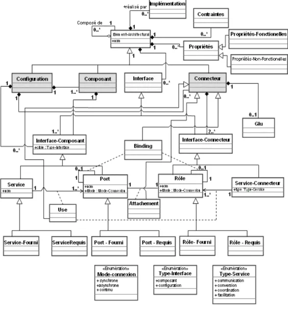
Figure 1 presents a meta-model of the COSA approach. COSA supports number of architectural elements including components, connectors and
795 configurations[13]. These architectural elements are types that can be instantiated to construct several architectures. An architectural element can have its own properties and its own constraints.
The key role of configurations in COSA is to abstract the details of different components and connectors. A configuration has a name and defined by an interface (ports and services), which are the visible parts of the configuration and support the interactions among configurations and between a configuration and its components.
Components represent the computational elements and data stores of a system. Each component may have an interface with multiple ports and multiple services. The interface consists of a set of points of interactions between the component and the external world that allow the invocation of the services. A component can be primitive or composite[13].
Connectors represent interactions among components; they provide the link for architectural designs. A COSA connector is mainly represented by an interface and a glue specification[13]. In principle, the interface shows the necessary information about the connector, including the roles, service type that a connector provides (communication, conversion, coordination, facilitation). Connectors can be composite or primitive.
Interfaces in COSA are first-class entities. They provide connection points among architecture elements. Likewise, they define how the communication between these elements can take place. The interface of a component/configuration is called port and the interface of a connector is called role. In addition to ports and roles interfaces have services that express the semantics of the element with which they are associated.
Properties represent additional information (beyond structure) about the parts of an architectural description. Typically they are used to represent anticipated or required extra functional aspects of architectural design. There are two types of properties: functional properties and non-functional properties. Functions that relate to the semantics of a system and represent the requirements are called functional properties. Meanwhile non-functional properties represent additional requirements, such as safety, security, performance and portability.
Constraints are specific properties, they define certain rules and regulations that should be met in order to ensure adherence to intended component and connector uses.
COSA UML PROFILE
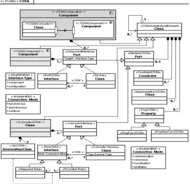
The goal of the COSA profile is to extend UML 2.0 in order to represent COSA architectural concepts. This profile aims to provide a practical way for integrating software architecture in the framework MDA (Model Driven Architecture), which unifies all modelling approaches[12].
A high level profile model provides the basic concepts to define COSA architecture. The meta-model of COSA is described as a UML stereotype package named «COSA». This package defines number of stereotypes: «COSAComponent», «COSAConnector», etc. These stereotypes correspond to the metaclasses of UML meta-model with all tagged values and its OCL 2.0 constraints[11]. Fig. 2 shows this meta-model. The second level permits to describe a particular architecture with the application of the profile. We can also define the value of each tagged value related to each stereotype. In this level the OCL constraints are checked and the final mapped system must conform to the UML profile. The third level presents a set of instances for component, connector and configuration types[12].
INTEGRATION OF COSA SOFTWARE ARCHITECTURE CONCEPTS INTO MDA
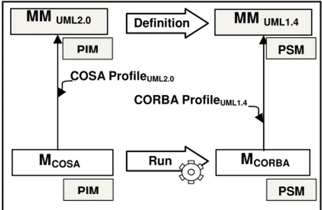
MDA (Model Driven Architecture) provides means to separate preoccupations of architectural aspects from implementation aspects by supporting the automation of the transformation from modelling to implementation. The main point is the independent of the model definition from the implementation platforms (CORBA, J2EE, etc.).
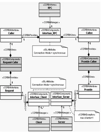
Fig. 2: The COSA profile
(Platform Independent Model) and in the PIM transformations toward PSM (Platform Specific Model).
Software architecture at the PIM level: PIM meta-model includes all architectural concepts relative to the COSA model. Using the mechanisms provided by UML profiles, we realize PIM transformations toward PSM and integrates all software architecture concepts into MDA platforms
Software architecture at the PSM level: the PIM transformations into PSM specify the way of which the MDA platforms (CORBA, J2EE, etc.) using models of
COSA architectures contains all intended architectural concepts for exploitation
PROFILE TRANSFORMATION
797 The mechanisms provided by UML profiles are very well suited to describing any implementation platform and the transformation rules between models. The definition of transformation process starts with defining a UML model conforms to the COSA meta-model, next producing automatically an implementation UML platform model as a target platform. After that, the model is evaluated by the platform profile.
We need to define the mapping rules from elements of the PIM to elements of PSM that make up the platform profile. The idea of elaborating these rules is to take each UML element of a PIM and find its corresponding PSM (the same semantically UML elements of PIM). Each element of transformation contains OCL expression [11], which permits transformation between the elements of COSA UML profile and platform UML profile and a filter to permit distinction between them. In addition, if the UML profile of the platform includes the specification of element relationships, then the transformation may be specified using operations deduced from theses relationships.
ILLUSTRATED TRANSFORMATION: FROM COSA (PIM) TO CORBA (PSM)
To illustrate how our strategy of mapping can be used, we apply it to COSA (PIM) to CORBA (PSM) transformation. Figure 3 presents the process of transformation from COSA software architecture to CORBA standard platform.
CORBA is a standard platform that provides simplicity of development by assembling prefabricated components but it does not support high levels of abstraction, especially composite components and connector concept. Meanwhile COSA supports composite components and defines connectors explicitly as abstract concepts.
Therefore, it is very useful to define an automatic transformation from COSA UML profiled (as an MDA PIM) to CORBA UML profiled (as an MDA PSM). The primary interest is a rapid mapping and smooth integration of COSA concepts into CORBA platform to achieve a higher level of abstraction and to help solving the problems of interactions among CORBA components. Compared to COSA, CORBA has concrete aspects and fully realizing designs.
COSA to CORBA transformation must follow incremental process that generates CORBA concepts from its corresponding COSA. This process starts with defining a UML model conforms to the COSA meta-model, next producing automatically a UML CORBA model as a target platform. After that, the model is
Fig. 3: COSA (PIM) to CORBA (PSM) transformation
evaluated by the CORBA UML profile. Figure 3 presents the process of transformation from COSA software architecture to CORBA platform.
Correspondence concepts: COSA UML profile[12] and CORBA UML profile[9] are based on two different UML meta-models; we need to map each COSA concept into CORBA concepts. The COSA-CORBA correspondence can be deduced easily from the same semantics between UML elements. COSA components are represented by UML 2.0 components. Since UML 2.0 component corresponds to a UML 1.4 class (the name of the class is the name of the component), a UML 2.0 component «COSAComponent» may be transformed to UML class «CORBAHome». COSA connectors, which are abstractions that include mechanisms of communication, are not defined explicitly in CORBA platform; we tried to find the closest CORBA concepts semantically. COSA connectors are represented by UML 2.0 classes. Since UML 2.0 class matches UML 1.4 class, so UML 2.0 Class «COSAConnector» is mapped to UML class «CORBAHome». Table 1 shows the concepts of COSA and their CORBA correspondence.
Mapping rules: Mapping rules must follow COSA to CORBA correspondence concepts. To elaborate each mapping rule we affect all elements relationships of source model (COSA) to its corresponding relationships on the target model (CORBA).
For example, COSA components, which are abstraction that includes mechanisms of computation, are represented by UML 2.0 components. Since UML 2.0 component corresponds to a UML 1.4 class (the name of the class is the name of the component), a UML 2.0 component «COSAComponent» may be transformed to UML class «CORBAHome». We include operations for acquiring attached elements
MCOSA MCORBA
PIM
Run COSA ProfileUML2.0
CORBA ProfileUML1.4
MM UML1.4 Definition
PIM
PSM
Table 1: COSA-CORBA correspondence
COSA concepts CORBA concepts «COSAConfiguration» Component «CORBAModule» Package «COSAComponent» Component «CORBAHome» Class «COSAConnector» Class
«Component-Interface» Port «CORBAComponent» Class «Connector-Interface» Port
«COSAPort» Interface «CORBAInterface» is synchronous «COSARole» Interface «CORBAEvent» is
asynchronous «Service» Class «CORBAEvent» Class «Connector-Service» Class
«COSAGlu» Association Class «IDL-Operation» Operation «COSAUse» Delegate connector «CORBAComponent» with two «COSABinding» Delegate interfaces provided and required connector
«COSAAttachment» Assembly connector
«COSAProp» Property «IDL-Attribute» Attribute
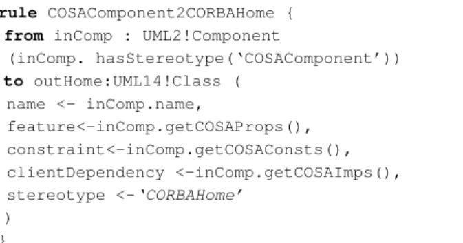
rule COSAComponent2CORBAHome {
from inComp : UML2!Component
(inComp. hasStereotype(‘COSAComponent’))
to outHome:UML14!Class ( name <- inComp.name,
feature<-inComp.getCOSAProps(), constraint<-inComp.getCOSAConsts(), clientDependency <-inComp.getCOSAImps(), stereotype <-‘CORBAHome’
) }
Fig. 4: Mapping rule from COSA component to CORBA home using ATL
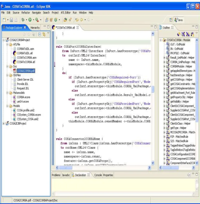
(getCOSAProps for acquired component properties, getCOSAImps for acquired component implementations and getCOSAContsraints for acquired component constraints) because COSA components contain only properties, implementations and constraints and then we impose this to the corresponding CORBA element (Fig. 4). This rule is expressed in ATL (Atlas Transformation Language)[2] .
COSA connectors, which are abstractions that include mechanisms of communication, are not defined explicitly in CORBA platform; we tried to find the closest CORBA concepts semantically. COSA connectors are represented by UML 2.0 classes (Fig. 5). Since UML 2.0 class matches UML 1.4 class, so UML 2.0 Class «COSAConnector» is mapped to UML class «CORBAHome».
COSA component/connector interfaces match UML 2.0 ports. Ports correspond to UML classes (name of the class is name of the port). So, a UML class (that represents a UML 2.0 component) must be attached to another class (that represents ports). Every class that represents a port (a UML class corresponds to
«CORBAComponent») must be attached to a UML class that represents a component or a connector (components and connectors correspond to «CORBAHome»). COSA provided ports/roles (or required ports/roles) are transformed to facets (or receptacles) for synchronous communication or to event sinks (or event sources) for asynchronous communication (Fig. 6). This rule is expressed in ATL (Atlas Transformation Language)[2].
An important aspect of COSA architecture is to offer a graph of component and connector types called configurations.
A UML 2.0 component can contain subcomponents and subclasses. COSA configurations are represented by UML 2.0 components. Since UML 2.0 component matches UML 1.4 Class (Fig. 7), UML 2.0 Component «COSAConfiguration» is mapped into UML class «CORBAModule».
rule COSAComponent2CORBAHome {
from inComp : UML2!Component
(inComp. hasStereotype(‘COSAComponent’))
to outHome:UML14!Class ( name <- inComp.name,
feature<-inComp.getCOSAProps(), constraint<-inComp.getCOSAConsts(), clientDependency <-inComp.getCOSAImps(), stereotype <-‘CORBAHome’
) }
Fig. 5: Mapping rule from COSA connector to CORBA home using ATL
rule COSAPort2CORBAInterface{
from InPort:UML2!Interface
(InPort.hasStereotype('Required-Port') or(InPort.hasStereotype('Provided-Port')
to utIntf:UML14!Interface( name <- InPort.name,
namespace<-thisModule.CORBAModule, )
do{
let tp:String = InPort.getStereotype()
if InPort.getPropObj(tp,‘Mode')=#synchnous
outIntf.stereotype<-'CORBAInterface'
else
outIntf.stereotype<- ‘CORBAEventPort’ feature<-inComp.getCOSAProps(), }
799
rule COSAConfiguration2CORBAModule {
from inConfig :UML2!Component
(Config.hasStereotype(‘COSAConfiguration’))
to outHome:UML14!Package ( name <- Config.name,
feature<-inComp.getCOSAProps(), constraint<-inComp.getCOSAConsts(), clientDependency <-inComp.getCOSAImps(), namespace<- thisModule.CORBAModel, ownedElement<- Config.ownedMember,
stereotype <-‘CORBAModule’ )
}
Fig. 7: Mapping rule from COSA connector to CORBA home using ATL.
System client-server {
Class Component Server{ Interface {
Connection-Mode =synchronous Ports provide {provide ;} }
Constraints {max-clients=1;} }
Class Component Client{ Interface {
Connection-Mode =synchronous Ports request {request ;} }
}
Class Connector RPC{ Interface {
Connection-Mode =synchronous Roles provide {callee ;} Roles request {caller ;} }
Glue {….} }
}
Fig. 8: The Client-Server system in COSA
Fig. 9: The Client-Server system using COSA UML 2.0 profile
Fig. 10: The Client-Server system using COSA UML 2.0 profile
Specific COSA connectors such as Use, Binding and Attachment are mapped into UML class (which is «CORBAComponent») and bound a provided interface (or event sink) into required interface (or event source). The principle of transformation using COSA and CORBA profiles is based on mapping each element in the COSA UML 2.0 profile into an element of the CORBA UML 1.4 profile.
Implementing the transformation: To illustrate how the COSA-CORBA transformation can be used, we apply it to the Client-Server system. Figure 8, shows the description of the system using COSA and Figure 9 presents the system after applying the profile. Figure 10 shows the architecture in CORBA after applying the transformation.
Fig. 11: COSA-CORBA transformation
• The meta-model of COSA (and CORBA) with all tagged values and OCL constraints is defined by the UML 2.0 (UML 1.4) profile
• The COSA-CORBA transformation is created.
This transformation describes how COSA model elements are matched and navigated, to create and initialize the elements of CORBA models
• The meta-model of COSA (and CORBA) with all
tagged values and OCL constraints is defined by the UML 2.0 (UML 1.4) profile
• COSA to CORBA transformation is configured and executed. The elaborated CORBA model is evaluated by its profile
COSA-CORBA transformation is defined using ATL transformation language[2] of RSM. Figure 11 shows the meta-models COSA and CORBA (in the left side) and the mapping rules (in the right side).
801 Fig. 12: The CORBA model of Client-Server system
RELATED WORK
In[4], Garlan points out that the world of software development and the context in which software is being used are changing in significant ways and these changes promise to have a major impact on how architecture is practiced. Rodrigues at al.[14], defined a mapping rules to transform an ACME description into a CORBA IDL specification. They focused on composing systems by exploring the ACME extensions facilities to include input/output ports in an ACME specification. They transformed almost every thing as an IDL interface, therefore, they did not really profit from the concepts available in CORBA IDL. ACCORD RNTL Project[1] is an open and distributed environment that aims to ease assembling components. It defines a semi-automated matching of concepts and an automated transformation of ACCORD model into CCM. This work is based on UML profiles to represent ACCORD and CCM
administration. Its approach allows a well separation between differentes aspects, but disagrees in the more integration of architecture concepts and architectural styles available in ADLs. More recently, in[15] Sanchez proposed an automatic transformation between requirement and architecture models for achieving a comfortable MDA framework.
Our approach of profile transformations can be seen as a base for mapping architectural concepts into an implicational plat-form. It offers number of advantages compared to related works, including:
• Fast mapping and smooth integration of most of SA concepts especially the concepts that are not defined explicitly such as connector, configuration, roles, to achieve a complete MDA framework
• Satisfying the higher level of abstraction of MDA plate-form by adopting high abstraction level from the UML Profile
• Automatic elaboration rules at the transformation process by using the same UML meta-models
However, our approach does not include the description architectural styles available and the capacity of automatic elaboration of the correspondence specification concepts between MDA PIM and MDA PSM meta-models for the transformation process.
CONCLUSION
In this research, we propose the integration of software architecture concepts into MDA platform and also we define a strategy of direct transformation using UML profile by mapping software architecture model and platform models in UML meta-model then elaborate correspondences concepts between results UML meta-models in mapping rules. We illustrated our strategy using an automatic transformation from COSA concepts to CORBA concepts. This strategy allows the mapping of COSA software architecture concepts that are specified in the UML profile (PIM) into CORBA platform (PSM).Related benefits of profile transformations is a higher abstraction level of MDA platform and more easily and more quickly integrating architectural concepts within MDA.
For our future work, we are considering the mapping at the meta-meta level, i.e. from an architectural meta-meta model into MOF. We are also considering the transformation in the other MDA platform and in the other SA-based.
REFERENCES
1. ACOORD RNTL Project, www.infres.enst.fr. 2. ATLAS group LINA. and INRIA Nantes, 2007.
ATL: Atlas Transformation Language. ATL User Manual version 7.0.
3. Fuentes-Fernández, L. and A. Vallecillo-Moreno, 2004. An Introduction to UML Profiles. European J. Inform. Prof., 7 (2): 6-13.
4. Garlan, D., 2000. Software Architecture: A Roadmap. Proc. of 22nd International Conference on Software Eng., pp: 91-101.
5. Manset, D., R.H.,Verjus and F. Oquendo, 2006. A formal architecture-centric, model-driven approach for the automatic generation of grid applications. Proc. of the 8th Int. Conf. on Enterprise Inform. Systems.
6. Marcos, E., C.J., Acu a and C.E. Cuesta, 2006. Integrating Software Architecture into a MDA Framework. Proc. of the 3th European Workshop on SA (EWSA’2006), France, pp: 128-143. 7. Medvidovic, N. and R.N. Taylor, 2000. A
classification and comparison framework for software architecture description languages. IEEE Trans. Software Eng., 26: 70-93.
8. Model Driven Architecture, www.omg.org/mda. 9. OMG, 2002. UML profile for CCM: Revised
Submission. document mars/03-01-01
10. OMG, October 2004. UML 2.0 Superstructure Specification: Revised Final Adopted Specification.www.omg.org/docs/ptc/04-10-02.pdf. 11. OMG, June 2005. UML OCL 2.0 Specification: Revised Final Adopted Specification. www.omg.org/docs/ptc/05-06-06.pdf.
12. Alti, A., T. Khammaci and A. Smeda, 2007. Representing and Formally Modeling COSA software architecture with UML 2.0 profile. IRECOS Review., 2 (1): 30-37.
13. Oussalah, M., A. Smeda and T. Khammaci, 2004. An explicit definition of connectors for component based software architecture. Proc. of the 11th IEEE Conference Engineering of Computer Based Systems (ECBS’2004), Czech Republic, pp: 44-51. 14. Rodrigues, M.N., L. Lucena and T. Batista, 2004. From Acme to CORBA: Bridging the Gap. First European Workshop on Software Architecture (EWSA’04)., pp: 103-114.