Object Modeling for User-Centered Development and
User Interface Design: The Wisdom Approach
Cê
Duarte Nuno Jardim Nunes
(Licenciado)
Tese Submetida à Universidade da Madeira para a
Obtenção do Grau de Doutor em Engenharia de Sistemas, especialidade de Informática
Professor Doutor João Bernardo de Sena Esteves Falcão e Cunha
Professor Associado do Dep. de Eng. Mecânica e Gestão Industrial da Faculdade de Engenharia da Universidade do Porto
A
Software engineering evolved significantly in the past decades and is definitively established as an engineering discipline. However, the past years completely changed the nature of the software industry. The Internet, information appliances, entertainment and e-commerce are today large industry segments, often dominated by startups or small companies that work in turbulent environments and face intense competition. Moreover, today there is an increasing diversity of computing devices that are becoming ubiquitous and reaching a growing number of users. In many situations users experience the user-interface of a software intensive system before they commit to purchasing a product or service. Therefore, usability is increasingly becoming an important issue in software development.
This thesis explores how object modeling can contribute to integrate usability engineering into modern software development providing benefits for both disciplines. The Wisdom UML-based approach presented here promotes a lightweight software development method encompassing three major aspects. The Wisdom process enables a new understanding of an UML-based process framework and provides an alternative to the Unified Process specifically adapted to promote a rapid, evolutionary prototyping model, which seamlessly adapts non-classical development lifecycles required by small software development teams. To accomplish this the Wisdom process relies on a new model architecture that promotes a set of UML-based models to support user-centered development and user-interface design. The Wisdom model architecture introduces new models to support user-role modeling, interaction modeling, dialogue modeling and presentation modeling. In addition, we propose a new analysis-level architecture that supports the integration of architectural significant user-interface elements. Finally, the Wisdom notation is a subset and extension of the UML that reduces the total number of concepts required to develop interactive systems. The Wisdom notation simplifies the application of the UML and defines a new set of modeling constructs necessary to support the Wisdom process and architecture.
K
Software Engineering
Usability Engineering
User-centered Design
User-Interface Design
Object Modeling
Unified Modeling Language
R
A engenharia de software desenvolveu-se significativamente nas últimas décadas afirmando-se hoje definitivamente como uma disciplina da engenharia. Todavia, os últimos anos alteraram por completo a natureza da indústria de software. A Internet, os dispositivos de informação, o entretenimento e o negócio electrónico são hoje mercados importantes, muitas vezes dominados por pequenas empresas que trabalham em ambientes turbulentos e extremamente competitivos. A crescente diversidade e ubiquidade dos sistemas computacionais serve hoje um número crescente de utilizadores que, muito frequentemente, experimentam a interface dos sistemas de software antes mesmo de se comprometerem a adquirir os produtos ou serviços. Desta forma, a “usabilidade” (facilidade de utilização) dos sistemas informáticos tornou-se uma questão central para a engenharia de software.
A presente tese explora a forma como a modelação por objectos pode contribuir para integrar métodos e técnicas da usabilidade no desenvolvimento moderno de software, permitindo benefícios para ambas as disciplinas. O método Wisdom, aqui apresentado, é uma nova proposta de um método de desenvolvimeno de software simplificado que compreende três aspectos importantes. O processo Wisdom define uma alternativa ao Processo Unificado especialmente adaptada ao desenvolvimento de software por pequenos grupos de pessoas de uma forma rápida e assente num modelo controlado de prototipificação evolutiva. O modelo de desenvolvimento subjacente ao processo Wisdom assenta numa nova arquitectura de modelos UML que suporta o desenvolvimento centrado nos utilizadores e o desenho de interfaces com o utilizador. A arquitectura Wisdom introduz novos modelos UML que suportam a modelação de perfis de utilizadores, da interacção, do diálogo homem-máquina, e das questões de apresentação, bem como, propõe um novo enquadramento dos elementos estruturais de análise UML, os quais permitem a integração de aspectos relacionados com a interacção. Finalmente, a notação Wisdom é um subconjunto e extensão do UML que reduz significativamente o número total de conceitos necessários para o desenvolvimento de sistemas interactivos. Por um lado simplifica a utilização do UML e, por outro, define um novo conjunto de elementos de modelação que suportam o processo e a arquitectura Wisdom.
P
C
Engenharia de Software
Engenharia da Usabilidade
Desenvolvimento Centrado nos Utilizadores
Desenho de Interfaces com o Utilizador
Modelação com Objectos
Unified Modeling Language
To the memory of my grandmother Cecília who taught me to dare
A
I am deeply indebted to many persons who have provided help, support and encouragement. First of all, I would like to thank my supervisor Prof. João Falcão e Cunha for his invaluable help and unselfish support throughout the preparation of this thesis. I thank him for teaching me to be a researcher.
I would also like to thank Prof. José Carmo for his caring and leadership. Warm thanks to Prof. Rita Vasconcelos for believing in my work and making our Department such a pleasant place to work. I would also like to thank all my other colleagues at the Department, in particular Leonel Nóbrega and Jorge Fernandes for their cooperation and fruitful discussions.
Much of the work presented here emerged from the collaboration with the OO&HCI people involved at the different international workshops. Special thanks to Dr. Mark van Harmelen for his vision, commitment and persistence in bringing OO&HCI to the R&D agenda; Dave Roberts for inspiring comments in object modeling for user-interface design; Tom Dayton for raising my interest in participatory techniques and the Bridge; Dr. Srdjan Kovacevic for the fruitful advices on tool issues; Prof. Fabio Paternò for the collaboration on the CTT to UML transformations; John Artim for inspiring comments on Wisdom; Prof. Jaelson Castro for initial collaboration on UCEP; and Prof. Larry Constantine for the availability to share the recent developments on usage-centered design.
I am grateful to all the companies, organizations, practitioners and students who helped me understand their needs and develop Wisdom.
I thank the IBM Ease of Use group, and particularly Roland Merrick, for their collaboration and support in providing the AUIML specs and tools for this project.
Finally I would like to express my warmest gratitude to my family and all my friends for making my life rich and joyful. Warm thanks to Angela and Emílio for their support and for being such great grandparents. I thank my brother Pedro for his friendship and for being such a perfect uncle. I express my heartfelt thanks to my parents for their support, care, and love and also for being such great grandparents -my mother for teaching me honesty and daring, and -my father for sharing his life-wisdom and instill that good luck is the product of integrity and hard work.
I give my greatest love to Andreia for sharing her life with me.
T
C
I. Introduction
1
I.1.
Motivation... 3
I.2.
Problem Statement ... 6
I.3.
Summary of Contributions ... 7
I.4.
Organization of the Thesis... 9
II. Background: A Brief Survey of Usability Engineering and Object Modeling
11
II.1. Usability of Software Intensive Systems: Definition, theories, Models and
principles... 13
II.1.1. Definition of Usability...13
II.1.2. Cognitive Frameworks of Usability...15
II.1.3. Usability principles and rules...24
II.2. A Brief Historical Perspective of Object-Oriented Modeling ... 29
II.2.1. The nature and Importance of Modeling...30
II.2.2. Object-Oriented Analysis and Design...32
II.2.3. The Unification Effort...33
II.2.4. Martin and Odell Foundation of Object-Oriented Modeling ...34
II.3. The Unified Modeling Language... 36
II.3.1. Goals and Definition of the UML...36
II.3.2. The UML Metamodel ...38
II.3.3. Extension Mechanisms and Future Development for UML Variants...39
II.4. Object-oriented process and methods: The Unified Process ... 41
II.4.1. Use-case Driven, Architecture-centric, Iterative and Incremental...42
II.4.2. The Unified Process Lifecycle...43
II.4.3. Architectural Representations in the Unified Process ...44
II.5. Usability and Software Development... 49
II.5.1. The Usability Engineering Lifecycle...49
II.5.2. User-centered Design ...52
II.5.3. Participatory Design...54
II.6. Architectures for interactive systems... 57
II.7. Model-Based Development of Interactive Systems... 60
II.7.1. Useful Models in Model-based Development Environments ...61
II.7.2. Task Notations...62
III. State of the Art: Object Modeling for User-Centered Development and User
Interface Design
71
III.1. Brief Historical Perspective of Object Modeling for User-Centered
Development and User Interface Design... 73
III.2. Recent Developments in Object Modeling for User-Centered Development
and User Interface Design... 77
III.2.1. Three Views of User Interfaces ... 77
III.2.2. A Unifying Framework for Object Modeling for User Interface Design ... 79
III.2.3. Dimensions for Integrating User-Interface Design into Software Development ... 80
III.3. Useful Models in Object Modeling for User-Centered Development and
User Interface Design... 82
III.3.1. Task Model... 82
III.3.2. Business (Process) Model... 85
III.3.3. Domain Model ... 87
III.3.4. Interaction model, User Interface and Interactive System Model... 88
III.4. Toward Integrated User-Centered Object-Oriented Methods... 90
III.4.1. Problems in Traditional Object-Oriented Methods... 91
III.4.2. Review of User Centered Object-Oriented Methods ... 92
III.4.3. A general framework for an Integrated User-Centered Object-Oriented Process ...101
III.5. Conclusion ... 107
IV. The Wisdom Method
111
IV.1. Application context: small software developing companies ... 114
IV.1.1. Underestimating the Importance of Small Software Developing Companies...114
IV.1.2. Differences in Software Engineering in the Small...117
IV.2. The Wisdom process... 122
IV.2.1. Evolutionary Prototyping...124
IV.3. The Wisdom architecture... 133
IV.3.1. Wisdom Model Architecture...134
IV.3.2. Wisdom User-Interface Architecture...138
IV.4. The Wisdom notation ... 142
IV.4.1. UML Extensions for the User Role Model ...144
IV.4.2. Revised UML Extensions for the Analysis Model...147
IV.4.3. UML Extensions for the Interaction Model...148
IV.4.4. UML Extensions for the Dialogue Model ...149
IV.4.5. UML Extensions for the Presentation Model ...152
IV.4.6. Valid Association Stereotypes Combinations...155
IV.5. The Wisdom Method ... 157
IV.5.1. Genealogy of Wisdom ...157
IV.5.2. Workflows, Development Activities and Models in Wisdom...160
IV.5.3. Requirements Workflow...161
IV.5.4. Analysis Workflow ...165
IV.5.5. Design Workflow ...169
IV.6. Differences Between Wisdom and other UC-OO Methods... 176
IV.7. Conclusion ... 179
V. Practical Experience and Results
181
V.1. Tool Issues ... 183
V.1.1. The XMI Interchange Format ...186
V.1.2. User Interface Tools...192
V.1.3. Appliance Independent UI Description Languages...200
V.2. Automatic Generation of Appliance Independent User Interfaces from
Wisdom Models... 203
V.2.3. Generalization: XForms and Flexible Automatic Generation ...213
V.3. Enhancing the Support for Task Modeling with Tool Interchange... 219
V.4. The Wisdom Notation and User-Interface Patterns... 223
V.5. Conclusion ... 227
VI. Conclusions and Future Developments
231
VI.1. Conclusions... 232
VI.2. Reflections and Future Developments... 235
VI.2.1. Software Process and Process Improvement...235
VI.2.2. UML and Notation Issues...236
VI.2.3. Tool issues...237
Index
238
L
Figure II.1 – The discipline of human-computer interaction (HCI) according to the ACM
Special Interest Group in HCI (SIGCHI) [ACM, 1992]...13
Figure II.2– Nielsen’s model of attributes of system acceptability [Nielsen, 1993]...15
Figure II.3 – The Model Human Processor – adapted from Card et al [Card et al., 1983]...16
Figure II.4– Typical Values for Parameters Describing Memories and Processors in the Model Human Processor (source: [Card et al., 1983])...18
Figure II.5 – The Model Human Processor Principles of Operation [Card et al., 1983] ...18
Figure II.6 – Definitions for a three level Goal-Task-Action Framework...19
Figure II.7– Review of GOMS Family of Methods (adapted from [John, 1995 ])...21
Figure II.8 – Conceptual Models...22
Figure II.9 – Norman’s Cycle of Interaction: The Seven Stages of Action and the Gulfs of Execution and Evaluation (adapted from [Norman and Draper, 1986]) ...23
Figure II.10 – Relationship between usability heuristics...28
Figure II.11 – Object orientation, object-oriented analysis and design and object-oriented programming languages (adapted from Martin and Odell [Martin and Odell, 1998])...29
Figure II.12 – Historical Perspective of Object-Oriented Analysis and Design Methods ...32
Figure II.13 – UML Genealogy and Roadmap (sources: [Kobryn, 1999] and [Martin and Odell, 1998]) ...34
Figure II.14 – Martin and Odell Foundation of Object-Oriented Modeling (adapted from Martin and Odell [Martin and Odell, 1998] ...34
Figure II.15 – The OMG meta-modeling architecture...39
Figure II.16 – The Unified Process Lifecycle (adapted from [Jacobson et al., 1999 ])...44
Figure II.17 – Generic Elements of Architectural Descriptions (adapted from Shaw and Garlan [Shaw and Garlan, 1996]) ...45
Figure II.18 – The 4+1 View Model of Architecture (adapted from [Kruchten, 1995])...46
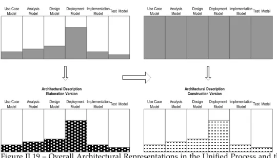
Figure II.19 – Overall Architectural Representations in the Unified Process and the Rational Unified Process ...47
Figure II.20 - The information space of the OOSE analysis framework ...48
Figure II.21 – The usability engineering lifecycle (adapted from Mayhew [Mayhew, 1999] ...50
Figure II.22 – A Taxonomy of participatory design practices (adapted from [Muller et al., 1993]...55
Figure II.23 - Conceptual Architectural Models for User-interface Objects ...57
Figure II.24 - The Seeheim and Arch conceptual models...58
Figure II.25 – Different approaches to task models (adapted from [Paternò, 2000 ]) ...63
Figure III.1 - The history of OOUI by Collins [Collins, 1995]...73
Figure III.2 – The three views of user interfaces ...78
Figure III.3 - The ECOOP’99 version of the CHI’97 framework, including the three issues – notation, process and architecture [Nunes et al., 1999; Kovacevic, 1998; Harmelen et al., 1997] ...79
Figure III.4 – Original draft of the CHI’98 User Task Model (from [Artim et al., 1998])...84
Figure III.5 – The Iceberg analogy of the designer’s usability model (source: [Roberts et al., 1998])...93
Figure III.6 – The Ovid Lifecycle (source: [Roberts et al., 1998])...93
Figure III.8 – The Idiom Process Framework (source: [Harmelen, 2001b]) ... 95 Figure III.9 – Model of the design activities in Usage-centered Design (source: [Constantine
and Lockwood, 1999]) ... 97 Figure III.10 – Models and logic dependencies in Usage-centered design (source:
[Constantine and Lockwood, 2001], updated version provided directly by the authors) ... 98 Figure III.11 – The User Centered Object-Oriented Process Framework [Nunes et al., 1999] ...102 Figure IV.1 – Characterization of small software development companies according to the
US Economic Census 1997 [USCensus, 1999]. ...116 Figure IV.2 – Improvement strategy versus organizational size and environmental
turbulence for (a) exploitation and (b) exploration in small and large companies (source [Dyba, 2000]) ...118 Figure IV.3 – The impact of (1) ability and (2) reliability on performance - M denotes the
mean performance of the distributions. (Source: [Dyba, 2000])...119 Figure IV.4 – The Wisdom Process Framework...122 Figure IV.5 – Wisdom as a process improvement strategy. From top to bottom the successive
introduction of Wisdom activities leading to the final process...126 Figure IV.6 – Three alternative use-case descriptions for the Withdraw cash use-case: (i)
Conventional, (ii) Structured, (iii) Essential...130 Figure IV.7 – Example of the Wisdom approach to use-case modeling for the ATM withdraw
cash example: (i) left-hand side – an adapted Bridge task flow produced in a participatory sessions and (ii) right-hand side – an essential task flows
expressed as an UML activity diagram...132 Figure IV.8 – The Wisdom Model Architecture...135 Figure IV.9 - The Wisdom user-interface architecture...139 Figure IV.10 – Application example of the conventional OO analysis framework versus the
Wisdom UI architecture: left-hand side - transcription of a solution provided in [Conallen, 1999]; right-hand side - the new solution based on the Wisdom UI
architecture...140 Figure IV.11 – UML Diagrams and Associated Concepts (estimation based on [Castellani,
1999])...142 Figure IV.12 – Process Workflows, Activities, Models and Diagrams in Wisdom ...143 Figure IV.13 - Alternative notations for the class stereotypes of the Wisdom user role model. ...146 Figure IV.14 – Participatory notation for the class stereotypes of the Wisdom user role model ..146 Figure IV.15 – Alternative notations for the class stereotypes of the Wisdom analysis and
interaction models...149 Figure IV.16 – Notation for the UML adaptation of ConcurTasktrees...151 Figure IV.17 – Presentation modeling elements in the UP (boundary), Ovid (object view),
Idiom (view), Usage-centered Design (interaction space) and Wisdom
(interaction space) ...154 Figure IV.18 – Valid association stereotypes combinations...155 Figure IV.19 – Wisdom Genealogy...158 Figure IV.20 – Dimensions of Software Complexity and Wisdom (adapted from [Royce,
1998])...159 Figure IV.21 – Activity Diagram for the Requirements Workflow Set in Wisdom...162 Figure IV.22 – Example of artifacts produced by the Requirements Workflow for the Hotel
Reservation System...164 Figure IV.23 – Activity Diagram for the Analysis Workflow in Wisdom...166 Figure IV.24 – Example of artifacts produced by the Analysis Workflow for the Hotel
Reservation System...168 Figure IV.25 - Activity Diagram for the Design Workflow in Wisdom ...170 Figure IV.26 - Artifacts from the Design Workflow for the Hotel Reservation System ...174 Figure IV.27 - Using the Bridge to create concrete GUIs in Wisdom...175 Figure IV.28 – Comparison between different UC-OO methods and Wisdom with respect to
the useful model for user-centered development and user-interface design. ...176 Figure V.1 – Jarzabek and Huang perspective on how to make CASE tools attractive to
developers (source: [Jarzabek and Huang, 1998])...186 Figure V.2 – Tool integration: (a) current situation and with open model Interchange (XMI)
[Brodsky, 1999] ...187 Figure V.3 – The OMG Repository Architecture and the SMIF (XMI) Interchange Standard
Figure V.7 - Specifications formats for High-level User Interface Development Tools
(adapted from [Myers, 1995])...195 Figure V.8 – AUIML Example for a simple user-interface asking a person’s complete name...205 Figure V.9 – Two examples of concrete user-interfaces automatically generated from a
AUIML document through: (i) a JavaSwing renderer and (ii) a DHTML
renderer...205 Figure V.10 – Overview of the two tracks in the UML to AUIML project, including an
overview of the XMI to AUIML transformation process...208 Figure V.11 – Overview of the Wisdom to AUIML Transformation process...209 Figure V.12 – An example of a Wisdom presentation model and the corresponding XMI
document ...210 Figure V.13 – An example of an AUIML document and a corresponding concrete user
interface produced by a Java Swing renderer...211 Figure V.14 – XForms as an appliance independent user-interface description language
(source: [W3C, 2001])...214 Figure V.15 – An example of an XForms-based flexible automatic generation process through
graphical exploration...217 Figure V.16 - A CTT Model expressed in the original CTT notation ...220 Figure V.17 - A CTT Model expressed in the CTT UML extension...221 Figure V.18 – An envisioned environment combining XMI-based tool interchange and
automatic generation informed by the dialogue model ...222 Figure V.19 – A solution for the Wizard pattern using Wisdom presentation and dialogue
A
ACM – Association for Computing Machinery API – Application Programming Interface
AUIML – Abstract User-Interface Modeling Language BPR – Business Process re-engineering
CASE – Computer Aided Software Engineering CHI – Computer-Human Interaction
CMM – Capability Maturity Model CSS – Cascading Style Sheets CTT – ConcurTaskTrees CUA - Common User Access CWM - Common Warehouse Model
DHTML – Dynamic Hypertext Markup Language DMS – Database Management Systems
DTD - Document Type Definition ERJ – Enterprise Java Beans
GOMS – Goals, Operator, Methods and Selection Rules GUI – Graphical User Interface
HCI – Human-Computer Interaction HTML – Hypertext Markup Language HTTP – Hypertext Transmission Protocol IDC – International Data Corporation IT – Information Technology
KLM – Keystroke-Level Model
MBDE – Model-Based Development Environment MIS – Management Information Systems
MOF – Meta Object Facility
OLE – Object Linking and Embedding OMG – Object Management Group OO – Object-Oriented
OO-SE – Object-Oriented Software Engineering OOUI – Object-Oriented User Interface
OOUID – Object-Oriented User Interface Design OVID – Object, View and Interaction Design PD – Participatory Design
SE – Software Engineering
SIGCHI – ACM Special Interest Group on Human Computer Interaction SMIF - Stream-based Model Interchange Format
SPI – Software Process Improvement
SSD – Small Software Development Company UCD – User Centered Design
UCEP – User-centered Evolutionary Prototyping UC-OO – User-Centered Object-Oriented UEL – Usability Engineering Lifecycle UI – User Interface
UID – User Interface Design
UIDE – User Interface Development Environment UIML – User-Interface Modeling Language UIMS – User Interface Management System UML – Unified Modeling Language UP – Unified Process
W3C – World Wide Web Consortium WIMP – Windows Icons Menus and Pointers WML – Wireless Markup Language
WWW – World Wide Web
XHTML – eXtensible HyperText Markup Language XMI –XML Metadata Interchange
I.
I
NTRODUCTION
"People Propose, Science Studies, Technology Conforms" Donald Norman person-centered motto for the 21st
century [Norman, 1993]
Software engineering conventionally targeted large, contract-based development for the defense and industry sectors. Although the software engineering discipline achieved significant improvements in that area, today modern software development faces completely different problems. The past years completely changed the nature of the software industry. The increasing diversity of computing devices, the Internet, and entertainment are today large industry segments, often dominated by startups or small companies that work under intense competition. Software engineering is faced today with the problem of adapting conventional methods, techniques and technologies to work in evolutionary, rapid, extreme and other non-classical styles of software development.
There is substantial evidence that attention to usability dramatically decreases the costs and increases productivity of software intensive systems. Nevertheless, developers rarely employ usability engineering methods and techniques in real-life projects. One important reason that usability engineering is not used in practice is the assumption that usability methods and techniques are costly and can only be used by large companies. However, the requirements for the next generation of user interfaces are quite different. The increasing diversity and connectivity of computing devices, and the new consumers of computing technology will have a profound effect on the future of user-interfaces.
engineering are today established fields; decades of research provided significant contributions that can help with the new and envisioned problems. The approach followed in this thesis is to bridge both fields taking advantage of what they best have to offer. The underlying principle is that some of the problems that software engineering faces today are the essence of what usability engineering promoted for years. Conversely, some of the problems that usability engineering currently faces are already successfully solved in the software engineering field.
I.1. M
OTIVATION
"We see computers everywhere but in the productivity statistics"
Attributed to Robert Solow [Landauer, 1997]
There are several well-documented examples of cost savings from employing usability engineering methods and techniques in software development. Studies consensually point out the evidence that usability engineering dramatically reduces costs (including training, support, errors, maintenance and late changes) and increases the benefits (including productivity and sales). It is not our remit here to make an extensive survey of studies about cost-justifying usability engineering, instead we summarize some references that motivate the need for usability engineering.
In a study about the impact of Information Technology (IT) in labor productivity, Landauer [Landauer, 1997] found out that the low return on investment from IT appears to be the missing piece in the post-war productivity slowdown puzzle. The author demonstrates this hypothesis through an extensive review of productivity statistics that clearly point out that: “the downturn of productivity growth over time coincident with widespread computerization, the concentration of growth failure in industries most heavily involved, the failure of labor productivity in services to respond positively to lavish information technology, the long term lack of correlation of business success with investment in this new technology” [Landauer, 1997]. This interpretation of the productivity statistics is sustained by the fact that computers are: (i) often used to support tasks that are irrelevant or detrimental to true productivity, and (ii) frequently not helpful when intended to increase worker or process efficiency [Landauer, 1997]. According to the author, the reason behind this problem is “foremost is reliance on traditional design and engineering methods that are not sufficient for the development of tools for intellectual work” [Landauer, 1997]. A shift towards user-centered design and usability engineering methods and techniques is predicted by Landauer to increase white-collar work efficiency by 40% per year, against 5% only applying conventional methods [Landauer, 1997].
[Karat, 1990]. Contatine and Lockwood refer an Australian study of hidden usability problems to be between $6,000AD and $20,000AD per year for each workstation [Constantine and Lockwood, 1999]. A mathematical model based on 11 studies suggests that usability engineering saves $39,000USD in a small project, $613,000USD in a medium project, and $8,200,000USD in a large project. In an entire book devoted to the theme of cost-justifying usability [Bias and Mayhew, 1994], Mayhew and Mantei estimate a complete planned usability-engineering program (for a large company in a large project) to cost $132,186USD and the benefits to be $209,490USD for an internal developer organization and $592,635 for a vendor company [Bias and Mayhew, 1994].
The studies mentioned before are usually associated with large companies and large projects. For instance, the cost estimated by Mayhew and Mantei for a usability-engineering program exceeds several times the entire development cost of most small companies. Recognizing the problem that usability engineering is perceived by small companies as expensive (and thus not cost-effective), Nielsen argued that the initial estimate of $132,186USD could be cut to $65,330USD if discount usability engineering methods where used [Nielsen, 1994]. An additional study of the usability budgets of 31 development projects confirmed the assumption that usability costs scale down with project size. Nielsen estimates that two person-years is the mean usability engineering effort in a project and that four person-years would be sufficient for most projects [Nielsen, 1994].
The impact of usability engineering in Internet economy is expected to be of even greater importance. As Nielsen points out “the web reverses the picture. Now, users experience the usability of a site before they have committed to using it and before they have spent any money on potential purchases.” [Nielsen, 2000]. Moreover, on the web the competition is not limited to other companies in the same industry: “With all the other millions of sites out there, you are in competition for the user’s time and attention, and web users get their expectations from the very best of all these other sites.” [Nielsen, 2000].
I.2. P
ROBLEM
S
TATEMENT
I.3. S
UMMARY OF
C
ONTRIBUTIONS
The main contributions of this dissertation are as follows:
• It describes principles and theories of usability engineering and object-oriented software engineering in terms understandable and relevant to modern interactive system development (see Chapter II);
• It describes the state-of-the-art in object modeling for user-centered development and user interface design. Discusses the useful models for object-oriented user interface design and reviews the integrated user-centered object-oriented methods (see Chapter III);
• It proposes an original process framework that provides an alternative to the Unified Process specifically adapted to promote a rapid, evolutionary prototyping model, which seamlessly adapts the requirements of small software development teams that typically work chaotically (see Chapter IV).
• It proposes an original UML model architecture defining a set of UML models required to build interactive system according to the best practices of object modeling for user-centered development and user-interface design (see Chapter IV). The Wisdom model architecture supports all the artifacts required for user-centered development and user-interface design, in particular user role modeling, interaction modeling, dialogue modeling and presentation modeling;
• It proposes an original extension of the UML analysis framework (the Wisdom user-interface architecture) that enables the integration of architectural significant user-interface elements in the conventional object-oriented analysis framework (see Chapter IV);
• It proposes a set of UML compliant modeling notations (the Wisdom notation), specifically adapted to develop interactive systems (see Chapter IV). The Wisdom notation adapts several recent contributions in the field of OO-UC to the UML style and standard; and also proposes new notations to support effective and efficient user-centered development and user-interface design. The original notational contributions introduced in the Wisdom notation enable the description of user profiles, user-interface architectures, presentation and dialogue aspects of interactive systems;
Wisdom process), with the best practices defined in usability engineering. Wisdom enables small groups of developers to work in highly turbulent and competitive environments taking advantage of what best characterizes them: enhanced communication, flexibility, fast reaction, improvisation and creativity (see Chapter IV);
• It demonstrates the successful application of the Wisdom method for appliance-independent user interface design, taking advantage of the UML tool interchange infrastructure (see Chapter V). It also demonstrates how the Wisdom models can effectively be used to automatically generate user interfaces rendered on multiple devices;
• It proposes a new envisioned tool environment for appliance independent interface design, using flexible model-based automatic generation of user-interfaces capable of being rendered on multiple platforms. It discusses how such an environment could leverage the UML tool interchange format and concentrate on highly focused user-centered tools that help developers on their tasks (see Chapter V);
I.4. O
RGANIZATION OF THE
T
HESIS
This dissertation consists of six chapters. The next chapter reviews the main theories and practical approaches in usability engineering and object-oriented software development, drawn from the human-computer interaction and software engineering journals and books.
Chapter III describes the recent developments in the field of object modeling and user interface design. The chapter starts with a brief historical perspective and carries on to a discussion of the useful models in object oriented user interface design. The chapter ends with a review of the methods that apply object-oriented principles for user-centered and user-interface design. From the review we present a new proposal for an integrated user-centered object-oriented process framework.
Chapter IV presents the Whitewater Interactive System Development with Object Models (Wisdom) method. The chapter starts discussing the application context of Wisdom (small software companies). The chapter continues presenting the three main contributions underlying the Wisdom method: the Wisdom process, architectural models and notation. Chapter IV ends with a detailed presentation of the Wisdom method for each major software development workflow: requirements, analysis and design. During the presentation specific techniques are discussed and examples provided.
Chapter V describes practical experiences of applying the Wisdom method in different aspects related to user interface design and specifically the impact regarding tool support. In this chapter we demonstrate how Wisdom can be used to automatically generate appliance-independent user interfaces. We then discuss how the Wisdom notation can take advantage of the UML interchange format. The chapter ends with a discussion of the Wisdom notation as a means of representing user-interface patterns.
II.
B
ACKGROUND
: A B
RIEF
S
URVEY OF
U
SABILITY
E
NGINEERING AND
O
BJECT
M
ODELING
“The ideal engineer is a composite ... He is not a scientist, he is not a mathematician, he is not a sociologist or a writer; but he may use the knowledge and techniques of any or all of these disciplines in solving engineering problems.”
—N. W. Dougherty (1955)
This chapter reviews the main theories and practical approaches in usability engineering and object-oriented software development. The main theories described in this chapter are drawn from the human-computer interaction and software engineering journals and books.
extracting quantitative measures from a qualitative model, is the notion of mental and conceptual models. A definition of mental and conceptual models is provided and related to Norman’s cycle of interaction – another widely used cognitive framework of usability. The cycle of interaction and the gulfs of execution and evaluation, are finally used to review a list of usability heuristics commonly used as principles and rules of user-interface design.
Since the goal of this chapter is to present usability in the context of software development, the remainder surveys recent developments in object modeling as the unifying paradigm of software development. We start from a broad definition of object modeling, as a technique for organizing knowledge, and its application to develop software intensive systems. We then address the nature and importance of modeling in software development, including the major aspects, such as semantic information (semantics), visual presentation (notation) and context. From this broad perspective we shift the focus to object-oriented analysis and design, the field that lead to the Unified Modeling Language de facto standard. We present a brief historical perspective of object-oriented analysis and design and use Martin and Odell foundation of object-oriented modeling to introduce the UML standard. Since the UML is a de facto standard, this section is focused on other less known aspects (language architecture and extension mechanisms) that are important for the contributions described in later chapters. The section ends emphasizing the independence of the UML from methodological background and presenting the major process framework of the UML – the Unified Process. Key aspects in this topic are related to architectural descriptions and patterns used in the Unified Process.
II.1. U
SABILITY OF
S
OFTWARE
I
NTENSIVE
S
YSTEMS
:
D
EFINITION
,
THEORIES
, M
ODELS AND PRINCIPLES
This section discusses usability of software intensive system, its definition and major theories, models and principles. For the purpose of this thesis we are concerned with usability in the context of the application of engineering principles to systematically build usable and economically viable interactive systems that support real work in an effective and efficient way that promotes satisfaction in use. However, this definition of usability engineering arises from the wider perspective of human-computer interaction (HCI), which is the discipline concerned with the design, evaluation and implementation of interactive computing systems for human use and with the study of major phenomena surrounding them [ACM, 1992].
Figure II.1 – The discipline of human-computer interaction (HCI) according to the ACM Special Interest Group in HCI (SIGCHI) [ACM, 1992]
Figure II.1 depicts the ACM SIGCHI vision of HCI. As we can see from this illustration, HCI concerns are much wider than those directly influencing usability engineering. Whenever applicable we use the term usability engineering to stress the focus of this thesis on the theories, models, principles, methods and techniques that are important for systematically building interactive systems.
II.1.1.Definition of Usability
“the extent to which a product can be used by specific users to achieve specific goals with effectiveness, efficiency and satisfaction in a specific context of use”. [ISO, 1998]
This definition relates to the quality of the interaction between the person who uses the product to achieve actual work and the product itself. The important features of the interaction are effectiveness, efficiency and satisfaction. Effectiveness concerns how well the user accomplishes the goals he wants to achieve with the system. Efficiency relates to the resources consumed in order to achieve the goals. Finally, satisfaction concerns how the user feels about the use of the system.
Usability has multiple components and is not a single one-dimension property of a user interface. According to Nielsen [Nielsen, 1993] usability is traditionally associated with the following attributes:
• Learnability – the system should be easy to learn, enabling even inexperienced users to perform rapidly the supported tasks;
• Efficiency – the system should be efficient in use, so that once the user has learned the system he should be able to achieve a high level of productivity;
• Memorability – the system should be easy to remember, allowing casual users to reuse the system without having to learn the system again;
• Error prevention – the system should prevent users from making errors, in particular, errors that damage users work must not occur. The system should enable users to recover from errors;
• Satisfaction – The system should be pleasant to use, fostering subjective satisfaction in use.
The precise definition of such usability attributes enables a systematic approach to usability as an engineering discipline. The components described above can be improved, measured and evaluated, and hence, constitute an alternative to speculative approaches to usability.
Usability is typically measured by testing a number of representative users performing a predetermined set of tasks. To determine the system overall usability we can take a mean value of the scores of a set of usability measures, or, recognizing that users are different, considering the entire distribution of usability measures [Nielsen, 1993]. Furthermore a number of methods for analyzing user interfaces quantitatively are also available, such as GOMS (and its variations) [Card et al., 1983], Hick’s law, Fitt’s law and Raskin’s measure of efficiency [Raskin, 2000] (see section II.1.2.2).
• Access rule – the system should be usable without help, prior experience or instruction by an experienced user in the application domain;
• Efficacy rule – the system should not interfere or impede efficient use by an experienced and skilled user;
• Progression rule – the system should accommodate and facilitate continuous advancement in knowledge, skill and facility as the user gains experience;
• Support rule – the system should support real work by making it simpler, faster, easier and more fun for the users to perform the tasks they are trying to accomplish and by creating new possibilities;
• Context rule – the system should be suited to the operational context (real conditions and environment) within which it will be deployed.
II.1.1.1.Usability and other Considerations
In the words of Nielsen: “Usability is a narrow concept compared to the larger issue of system acceptability” [Nielsen, 1993]. System acceptability concerns the wider extend to which a system satisfies all the needs and requirements of the user and other potential stakeholders directly or indirectly influenced by the system. Acceptability is a combination of social and practical attributes. Given that a system is socially acceptable – meaning that it conforms to the existing social, cultural and moral guidelines – we can enumerate a number of practical acceptability attributes. One example of such attributes is illustrated in Figure II.2.
System Acceptability
Social Acceptability
Practical Acceptability
Usefulness
Utility
Usability
Cost
Compatibility
Reliability
Easy to learn
Efficient to use
Easy to remember
Few errors
Subjectively pleasing Figure II.2– Nielsen’s model of attributes of system acceptability [Nielsen, 1993]
II.1.2.Cognitive Frameworks of Usability
The dominant frameworks used in HCI to understand and represent how humans interact with computers are based on the cognitive psychology perspective. Cognitive psychology is a theoretical perspective that focuses on how human beings achieve their goals in terms of cognitive tasks that involve transforming and processing information from the sensory input.
characterized as information processors. This approach resembles the ones used to describe computer systems in terms of memories, processors, their parameters and interconnections. This description is approximate in the sense that it only intends to predict human-computer interaction and not to explain the physiological processes that happen in the brain.
II.1.2.1.The Model Human Processor
The Model Human Processor is an extension of the basic information-processing model that sees the human mind as a series of ordered processing stages [Preece, 1995]. This simplified model starts with the sensory input stimuli and comprises a four-stage model of encoding, comparison, response selection, response execution, and finally ends with the output.
The two main extensions of the basic information-processing model are the inclusion of attention and memory processes. They form the basis of the Model Human Processor (see Figure II.3) which consists of three interacting systems: the perceptual system, the motor system and the cognitive system – each with it’s own memory and processor [Card et al., 1983].
Long-term Memory
Working Memory
Visual image store
Auditory image store
Perceptual processor
Motor processor
Cognitive processor
Figure II.3 – The Model Human Processor – adapted from Card et al [Card et al., 1983]
The cognitive system connects the inputs from the perceptual system to the right outputs of the motor system. The process consists in receiving symbolic coded information from the working memory, eventually combining that information with previously coded information in the long-term memory, and decides how to respond. Since most of the human tasks are complex and involve learning, retrieval of facts, or problem solving; the memories for the cognitive system are more complicated. The working memory holds the intermediate products of thinking and the symbolic representations produced by the perceptual system. The working memory consists of a subset of the symbolic elements (chunks) in the long-term memory that are active to support the mental operations. The most important characteristics of the working memory are its limited capacity to hold information, in amount and time. The long-term memory holds the available mass of knowledge in the form of a network of related chunks accessed associatively from the contents of the working memory. The contents of the long-term memory comprise facts, procedures and history. Information in the long-term memory must be encoded in symbolic form – there is no direct way of storing information from the sensory inputs into the long-term memory.
The motor system is responsible for carrying out responses to the sensory inputs. Thought is transferred into action, using information in the working memory, by activating patterns of voluntary muscles.
The Model Human Processor as a Framework for Estimating and Evaluating User Interfaces
The Model Human Processor framework, presented in Figure II.3 and briefly describe before, provides a means of characterizing the various cognitive processes that are assumed to underlie the performance of a task. From this conceptual model several approaches were developed to translate qualitative descriptions into qualitative measures – they are known as GOMS (goals, operations, methods and selection rules) family of models [Card et al., 1983].
The GOMS family of models is based on a set of parameters that describe memories and processors. The most important parameters for memories are [Card et al., 1983]:
• µ - The storage capacity, in items;
• δ - The decay time of an item, and
• κ - The main code type (physical, acoustic, visual, semantic, etc.).
Conversely the most important parameter for processors is:
• τ - The cycle time.
Parameter Perceptual System Cognitive System Motor System
Memories
µ µVIS = 17(7~17) letters
µAIS = 5(4.4~6.2) letters
µWM(pure) = 3(2.5~4.1) chunks
µWM(effective) = 7(5~9) chunks
δ δVIS = 200(90~1000) msec.
δAIS = 1500(900~3500) msec.
δWM(1 chunk) = 73(73~226) sec.
δWM(3 chunks) = 7(5~34) sec.
δLTM = ∞
κ κVIS = physical
κAIS = physical
κWM = acoustic or visual
κLTM = semantic
Processors
τ τP = 100(50~200) msec. τC = 230(70~700) msec. τM.= 70(30~100)
msec.
Figure II.4– Typical Values for Parameters Describing Memories and Processors in the Model Human Processor (source: [Card et al., 1983])
Furthermore, the parameters obey a set of principles, called the principles of operation, which enable qualitative predictions and measurements of user behavior. The principles of operation for the Model Human Processor are summarized in Figure II.5.
The Model Human Processor Principles of Operation
• P0. Recognize-act Cycle of the Cognitive Processor – on each cycle of the cognitive processor, the contents of the working memory initiate actions associatively linked to them in long-term memory, these actions in turn modify the contents of the working memory.
• P1. Variable Perceptual Processor Rate Principle – the perceptual processor cycle time τP varies
inversely with stimulus intensity.
• P2. Encoding Specificity Principle – specific encoding operations performed on what is perceived determine what us stored, and what is stored determines what retrieval cues are effective in providing access to what is stored.
• P3. Discrimination Principle – the difficult of memory retrieval is determined by the candidates that exist in memory, relative to the retrieval cues.
• P4. Variable Cognitive Processor Rate Principle – The cognitive processor cycle time τc i s
shorter when greater effort is induced by increased task demands or information loads, it also diminishes with practice.
• P5. Fitt’s law – the time Tpos to move the hand to a target of size S which lies a distance D away
is given by: Tpos=IMlog ( /2 D S+0 5. ), where IM=100 70 120[ ~ ] sec/m bit.
• P6. Power Law of Practice – the time Tn to perform a task on the nth trial follows a power law:
Tn=T n
− 1
α, where α =0 4 0 2. [ . ~ . ]0 6.
• P7. Uncertainty Principle – decision time T increases with uncertainty about the judgment or decision to be made: T=ICH, where H is the information-theoretic entropy of the decision and
IC=150(0~157) msec/bit. For n equally probable alternatives (called Hick’s Law)
H=log (2 n+1), for n alternatives with different probabilities, pi, of occurrence,
H=
∑
ipilog ( /21pi+1).• P8. Rationality Principle – a person acts so as to attain his goals through rational actions, given the structure of the task and his inputs of information and bounded by limitations on his knowledge and processing ability: Goals + Task + Operators + Inputs + Knowledge + Process-limits → Behavior.
• P9. Problem Space Principle – the rational activity in which people engage to solve a problem can be described in terms of: (i) a set of states of knowledge, (ii) operators for changing one state into another, (iii) constraints on applying operators, and (iv) control knowledge for deciding which operator to apply next.
II.1.2.2.The GOMS Family of Models
Since Card and colleagues presented the original concept of GOMS, several authors extended the original method [John and Kieras, 1996a; Kieras, 1988; John, 1990; John and Gray, 1995]. They also outlined several significant gaps in cognitive theory to address some HCI concerns - for instance fatigue, user-acceptance and fit to organizational life [John and Kieras, 1996a ]. Despite that, the GOMS model is one of the few widely known HCI conceptual theories and it has been widely discussed, experimented and tested.
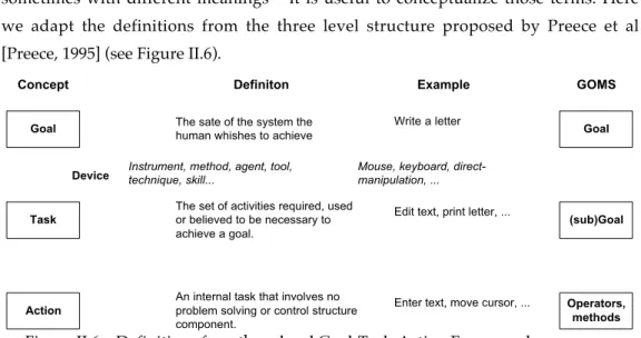
GOMS is a method for describing a task and the user’s knowledge of how to perform the task in terms of Goals, Operators, Methods and Selection rules [John, 1995]. Since the concepts underlying the GOMS model are widely used in the HCI field – sometimes with different meanings – it is useful to conceptualize those terms. Here we adapt the definitions from the three level structure proposed by Preece et al [Preece, 1995] (see Figure II.6).
Goal
Task
Action
Concept Definiton Example
Device
The sate of the system the human whishes to achieve
The set of activities required, used or believed to be necessary to achieve a goal.
An internal task that involves no problem solving or control structure component.
Instrument, method, agent, tool, technique, skill...
Write a letter
Edit text, print letter, ...
Enter text, move cursor, ...
Mouse, keyboard, direct-manipulation, ... GOMS Goal (sub)Goal Operators, methods
Figure II.6 – Definitions for a three level Goal-Task-Action Framework
A goal can be defined as the state of the system that the human whishes to achieve. A goal, sometimes called an external task, can be achieved using some instrument, method, agent, tool, technique, skill, or generally, some device that enables the human to change the system to the desired state. A task (or more specifically an internal task) is defined as the activities required, used or believed to be necessary to achieve a goal using a particular device. A task is, hence, a structured set of sequential activities that a human has to do (or thinks he as to do) in order to accomplish a goal. Finally an action is defined as an internal task that involves no problem solving or control structure component.
well-learned sequences of sub-goals and operators that can accomplish a goal. A classic example of a method is deleting a paragraph in a word processor – place the cursor at the beginning of the paragraph, drag to the end of the paragraph, release highlighting the paragraph and press the delete key. Finally, if there is more than one method to accomplish the same goal, selection rules apply, that is, decide what method to use in a particular circumstance [John, 1995 ].
There are at least four different versions of the original GOMS method that achieved a broad use [John, 1995 ]. The original formulation proposed by Card et al [Card et al., 1983], which is a loosely defined demonstration of how to express a goal hierarchy, methods and operators, and to formulate selection rules. A simplified version, also defined by Card and colleagues, that uses only keystroke level operators and no goals, methods and selection rules. The simplified version is called the Keystroke-Level Model (KLM) and enables simple calculations through lists of keystrokes and mouse movements, supported with a set of simple heuristics used to “place mental operators”. A more rigorous version, called NGOMSL and proposed by Kieras [Kieras, 1988], presents a procedure for identifying all GOMS components, expressed in a form similar to an ordinary programming language. NGOMSL includes rules-of-thumb about how many steps can be in a method, how goals are set and terminated, and what information needs to be remembered by the user while doing a task [John and Kieras, 1996a ]. Finally John [John, 1990; John and Gray, 1995] proposed a parallel activity version, called CPM-GOMS, which uses cognitive, perceptual and motor operators in a PERT chart to show how activities can be performed in parallel.
Version of GOMS
Type of System
Predictions Uses of
Analysis
Task Domain
Original Single-user
passive Operator, sequence.Performance time. Working memory errors. Learning time. Method verification. Comparison of systems. Documentation design. Text editor. Operating system. VLSI CAD. Spreadsheet. Hypercard. Videogames. Keystroke-Level Model (KLM)
Single-user
passive Performance time. Methodverification. Redesign justification. Text editor. Spreadsheet. Map digitizer. NGOMSL Single-user
passive Operator sequence.Performance time. Learning time. Working memory errors. Method explanation. Method verification. Redesign. Text editor. Ergonomic CAD. CPM-GOMS Single-user passive, surrogate user
Performance time. Comparison of systems. Method verification. Telephone operator workstation. Airline schedule.
Figure II.7– Review of GOMS Family of Methods (adapted from [John, 1995 ])
II.1.2.3.Recent Developments in Cognitive Psychology Frameworks
Theoretical approaches that describe the activity of the brain using the computing metaphor, and its’ underlying concepts (buffers, memories, processors, etc.), were popular and appealing until the 80s. The popularity of these approaches was related to the possibility of testing those models. Since the 80s different approaches have evolved in the HCI field. The new approaches are commonly known as the connectionist and computational approaches [Preece, 1995].
The computational approaches continue to adopt the computer metaphor as the main theoretical framework. However, the emphasis has shifted from the information-processing framework (where the information is processed) to modeling human performance in terms of when information is processed.
The connectionist approaches adopt the brain metaphor in which cognition is represented as a set of interconnected nodes in the form of a neural network or parallel distributed processing framework. Hence, cognitive processes are viewed as activations of nodes in the network and the connections between them instead of the process of manipulating and processing information.
II.1.2.4.Mental and Conceptual Models
One of the problems of extracting a quantitative model, such as GOMS, from a qualitative description of user performance is ensuring that the two are connected. In particular, Barnard [Barnard, 1987], noted that the form and content of the GOMS family of models is relatively unconnected with the Model Human Processor. One way of dealing with such oversimplified conceptualizations of human-behavior concerns conceptual or mental models.
Mental models refer to representations people construct in their minds of themselves, others, objects and the environment to help them know what to do in current and future situations [Preece, 1995]. When such models refer to software or physical systems they are usually known as conceptual models. A good conceptual model allows humans to predict the effects of their actions: “without a good (conceptual) model we operate by rote, blindly; we do operations as we were told to do them; we can’t fully appreciate why, what effects to expect, or what to do if things go wrong (…)” [Norman, 1988].
Norman defines a conceptual user model, in the context of HCI, as “the model people have of themselves, others, the environment, and the things with which they interact. People form mental models through experience, training and instruction” [Norman, 1988].
There are different mental models with respect to the development of interactive systems (see Figure II.8). The design model is the designers’ mental model of the system, it reflects the model that designers’ build when developing the system. The user model is the mental model humans develop when interacting with the system, through experience, training and instruction. Finally, the system image is the physical (perceivable) structure of the actual system built. Since all communication of the users with the system happens through the system image, if the system image doesn’t reflect clearly and consistently the design model there is a good change that users will form wrong mental models.
Design Model
Designer User
iMac
User's Model
System Image
Figure II.8 – Conceptual Models
knowledge can be very productive helping designers construct an appropriate model of the system. Furthermore, conceptual models can provide a good heuristic tool. Examples of such utility are evident, for instance, in several usability heuristics described in the following sections.
II.1.2.5.Norman’s Cycle of Interaction
Norman’s Cycle of Interaction is another well-known cognitive framework of HCI [Norman and Draper, 1986]. This model provides a way of identifying the main phases in a user interaction - the seven stages of action. The author claims that, since the stages are not discrete entities, the cycle forms an approximate model and not a complete psychology theory. This model provides a structured framework for design and evaluation of interactive systems. The seven stages of action are:
• Forming the goal
• Forming the intention
• Specifying an action
• Executing the action
• Perceiving the state of the world
• Interpreting the state of the world
• Evaluating the outcome
Goals
Intention
Specification
Execution
Evaluation
Interpretation
Perception
iMac
Mental
Physical
Gulf of Evaluation Gulf of
Execution
Figure II.9 – Norman’s Cycle of Interaction: The Seven Stages of Action and the Gulfs of Execution and Evaluation (adapted from [Norman and Draper, 1986])
that can be performed to satisfy the intention) that is still a mental event. Finally the actions are executed, that is, performed upon the physical world.
The stages of evaluation (at the right-hand side of Figure II.9) start with the perception of the world. This perception of the physical world is interpreted according to the expectations and then evaluated, that is, compared with respect to the intentions and goals (part of the stages of execution). The Cycle of Interaction corresponds to the coupling of both sets of stages with the common goal.
The Gulfs of Execution and Evaluation
The model reflected by Norman’s cycle of iteration enables the identification of several gulfs that separate mental intentions and interpretations from physical actions and states. Each gulf indicates a potential problem for the users since it reflects the distance between the mental representations of the users (conceptual model) and the physical components and states of the environment (physical model) [Norman and Draper, 1986].
• The gulf of execution – “The gulf of execution is the difference between the intentions of the user and the allowable actions the system provides”;
• The gulf of evaluation – “The gulf of evaluation reflects the amount of effort that the person must exert to interpret the physical state of the system and to determine how well the expectations and intentions have been met”;
Some of Norman’s stages correspond roughly to Foley and Van Dam’s separation of concerns [Foley et al., 1990]. The user forms a conceptual intention, reformulates it into the semantics of several commands, constructs the required syntax, and eventually produces the lexical tokens.
II.1.3.Usability principles and rules
Many sources define general rules and principles for usability. Those principles and rules, also called usability heuristics, provide design guides for interactive system development and can be effectively used in discount usability engineering heuristic evaluation [Nielsen, 1993].
In a study of the impact of the explanatory power of usability heuristics, Nielsen performed a factor analysis of the scores of 249 usability problems with respect to a list of 101 usability heuristics [Nielsen, 1994]. From this statistical analysis the author derived a candidate set of 10 heuristics providing a broad coverage of the usability problems found in common interactive applications. This candidate set of heuristics includes the following principles:
H2. Match between system and real world – the system should speak the users’ language with concepts familiar to the user in a logical and natural order, rather then system-oriented terms;
H3. User control and freedom – provide ways for the user to escape from unwanted states without going through extended dialogues. Support undo and redo;
H4. Consistency and standards – avoid different terms, situations and actions with the same meaning. Follow platform conventions, standards and guidelines;
H5. Error prevention – design the system carefully to prevent problems from occurring in the first place;
H6. Recognition rather than recall – make objects, actions and options visible. The user should not have to recall information from one part of the dialogue to another. Instructions for use of the system should be visible and retrievable whenever appropriate;
H7. Flexibility and efficiency of use – accommodate different experience levels providing accelerators for expert users that are invisible to novices. Allow users to tailor frequent actions;
H8. Aesthetic and minimalist design – avoid information in dialogues which is irrelevant and rarely needed, hence diminishing the visibility of relevant information;
H9. Helping users recognize, diagnose and recover from errors – error messages should be expressed in simple language, precisely indicating the problem and constructively suggesting a solution.
H10. Help and documentation – documentation and help, when required, should be focused on user tasks and easy, concise and easy to search.
In the following sections we present some of the most important usability principles found in the literature. The aim here is not to survey all of the published usability principles, but rather to complement Nielsen’s candidate set of heuristics with design-oriented advice. For a complete review of usability heuristics for evaluation and design purposes refer to [Baecker, 1995]. We then relate those principles and rules with the candidate set of heuristics proposed by Nielsen.
II.1.3.1.Norman’s Principles of Design for Understandability and Usability
Norman’s seven stages of action can be used as design aids or heuristics, because they provide a basic checklist to ensure the gulfs of execution and evaluation are bridged [Norman and Draper, 1986]:
![Figure II.1 – The discipline of human-computer interaction (HCI) according to the ACM Special Interest Group in HCI (SIGCHI) [ACM, 1992]](https://thumb-eu.123doks.com/thumbv2/123dok_br/15672516.624188/39.892.292.717.527.845/figure-discipline-computer-interaction-according-special-group-sigchi.webp)
![Figure II.2– Nielsen’s model of attributes of system acceptability [Nielsen, 1993]](https://thumb-eu.123doks.com/thumbv2/123dok_br/15672516.624188/41.892.225.768.675.867/figure-ii-nielsen-model-attributes-system-acceptability-nielsen.webp)
![Figure II.3 – The Model Human Processor – adapted from Card et al [Card et al., 1983]](https://thumb-eu.123doks.com/thumbv2/123dok_br/15672516.624188/42.892.272.612.563.967/figure-ii-model-human-processor-adapted-card-card.webp)
![Figure II.4– Typical Values for Parameters Describing Memories and Processors in the Model Human Processor (source: [Card et al., 1983])](https://thumb-eu.123doks.com/thumbv2/123dok_br/15672516.624188/44.892.174.740.113.319/figure-typical-values-parameters-describing-memories-processors-processor.webp)
![Figure II.11 – Object orientation, object-oriented analysis and design and object- object-oriented programming languages (adapted from Martin and Odell [Martin and Odell, 1998])](https://thumb-eu.123doks.com/thumbv2/123dok_br/15672516.624188/55.892.231.775.838.1085/figure-object-orientation-oriented-analysis-oriented-programming-languages.webp)
![Figure II.13 – UML Genealogy and Roadmap (sources: [Kobryn, 1999] and [Martin and Odell, 1998])](https://thumb-eu.123doks.com/thumbv2/123dok_br/15672516.624188/60.892.178.725.127.501/figure-uml-genealogy-roadmap-sources-kobryn-martin-odell.webp)
![Figure II.21 – The usability engineering lifecycle (adapted from Mayhew [Mayhew, 1999]](https://thumb-eu.123doks.com/thumbv2/123dok_br/15672516.624188/76.892.180.736.175.800/figure-ii-usability-engineering-lifecycle-adapted-mayhew-mayhew.webp)
![Figure II.22 – A Taxonomy of participatory design practices (adapted from [Muller et al., 1993]](https://thumb-eu.123doks.com/thumbv2/123dok_br/15672516.624188/81.892.217.784.100.610/figure-ii-taxonomy-participatory-design-practices-adapted-muller.webp)
