_____________________________
*)
Corresponding author: [email protected]
doi:
10.2298/SOS1201003N
UDK 519.872:622.785
Three-Dimensional Computer Simulation of Grain Coarsening
During Sintering
Zoran S. Nikolic
University of Nish, Faculty of Electronic Engineering, Department of
Microelectronics, 18000 Nish, Aleksandra Medvedeva 14, P.O. Box 73, Serbia
Abstract:
This paper presents a computational study of the three-dimensional computer simulation of grain coarsening using a sintering model based on sintering law (a rate law of inter-grain distance reduction) describing the evolution of neck geometry.
Keywords: Sintering; Neck growth; Grain coarsening; Computer simulation.
1. Introduction
Coarsening and grain growth accompany skeletal structure evolution during sintering of powder compacts [1,2]. In general, the sintering process is driven by a decrease in the overall potential energy via reduction of the solid-vapor interfacial energy balanced with the growth of solid-solid interfaces within the sintered part. The growth of a neck between touching solid grains can occur via surface, grain boundary and volume diffusion or vapor transport via evaporation and condensation. Based on these diffusion mechanisms, a number of sintering models describing the evolution of neck geometry between two grains or an array of connecting grains (skeletal structure) have been developed [3-6]. Such sintering models introduce an assumption that the driving force can be principally modeled on the basis of the local grain and neck curvature. For traditional two- and three-grain models good agreement between predicted evolution of neck geometry and neck growth experiments was obtained, but extension from simple models to multi-grain models for densification of a powder compact was usually failed due to unaccounted geometric changes and topological constrains [7], such as local grain rearrangements connected with formation of new contacts between grains involved into the same or different solid skeletons [8].
2. Model topology
For simulation of solid state sintering it is convenient to use multi-grain models of regular shape because they need to store only the position, orientation and size of each grain. Thus, we will use a microstructure consisting of N spherical grains, which will be represented
by a finite dimensional vector and by 3-D domains of regular shape, i.e. Gl =(Cl,Rl), where
} ,..., 2 , 1
{ N
∈
l and Cl =(xcl,ycl,zcl) is the center of the mass of l-th spherical grain of radius
l
R in space.
The geometry and topological aspects of multi-grain model can be most easily described by the skeleton network in which grain centers are identified by vertices and a link
(center-to-center distance) joins a pair of vertices Ck and Ci, where the length of link Dki
can be computed as the Euclidean distance function d(Ck,Ci) between their centers in 3-D [10]. The network corresponding to a model of connected grains is thus made up of a unique, interconnected set of closed polygons.
3. Neck growth
Generally speaking, modeling of sintering of two unequal-sized grains is difficult for several reasons. The grain boundary between such grains is not planar and tends to migrate due to grain boundary diffusion and deposition/removal of material at the grain boundary. Without precise knowledge of the grain boundary mobility it is difficult to predict this grain boundary migration [11]. Therefore, in order to avoid arbitrary assumptions, our model does not contain grain boundary diffusion. The role of the grain-boundary consists solely in defining a dihedral angle at the grain boundary-surface intersection.
(a) (b)
Fig. 1 Two-grain sintering model showing specified geometric variables and contact
geometry evolution. (a) Initial state represented by initial network link length Dkio (F is the
topological constraint force), and (b) after sintering time t, where ΔDkit is the change in that distance due to densification.
The basic sintering kinetics will be obtained using idealized two-grain sintering model (Fig. 1a),
) (D f t D Δ =
Δ , (1) where ΔD is the decrease in center-to-center distance for a given time step Δt and f(D) is the particular neck growth law. Assuming that at time point t+Δt the decrease of link length
t ki
t t ki t ki t t
ki D D
D+Δ = − +Δ
Δ (2)
then by substituting equation (2) into equation (1) each network link Dkit between a pair of
vertices Ck and Ci can be updated by sintering transformation
t D f D
Dkit+Δt a tki− ( kit )⋅Δ . (3) Knowing the geometry changes caused by densification mechanisms, the simulation proceeds to the next time point tat+Δt and repeats the procedure (3) until a final sintering time is met.
4. Skeleton structure
The microstructure is characterized by two bonds that form during sintering: bonds that form early during sintering (primary bonds) and bonds that form as densification induced new contacts (secondary bonds). Skeletal structure evolution will be simulated by an
algorithm based on grain-level methodology, which will be applied for selected grain Gn, }
,2,..., 1
{ N
n∈ .
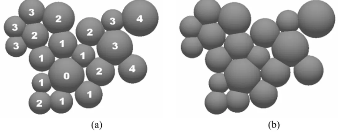
(a) (b)
Fig. 2 The skeleton of nineteen grains. (a) Initial structure with assigned grain levels. (b) Skeleton structure after neck growth between central grain (Level 0) and its first neighbors (Level 1), as well as after adjustment of position of residual grains (Levels 2, 3 and 4).
Fig. 3 The simplified two-grain model for sintering, where two grains of radii R1 and R2 are
Fig. 2 shows skeletal structure consisting of nineteen connected grains. Computation starts with levels definition (Fig. 2a), where grain labeled by zero level can be selected at random. Note that in such system characterized by relatively high packing density, extensive grain rearrangement is not possible. After computation of new center-to-center distances due
to the neck growth between zero-level grain and its first neighbors (level 1), all vertices C of l remaining grains (higher levels neighbors) must be adjusted. This procedure will be repeated for all grains. Fig. 2b shows a typical 3-D computed microstructure obtained after several time steps. Due to the neck growth, densification manifested by decrease in center-to-center distances as well as by relatively small grain rearrangement occurs.
4.1. Equilibrium dihedral angle
Initial model will be based on assumption that solid-phase domains make point contacts with each other (touching domains) followed by neck formation (Fig. 3), where the time-dependent neck radius, a, is defined by equation (3). These two solid grains in contact form a three-dimensional dihedral angle
2 1 ψ ψ
ψ = + , (4) where the dihedral angles ψ1 and ψ2 are determined as
) ( tan 1 1 1= − a d
ψ ,ψ2=tan−1(a d2). (5) The neck will grow during sintering, and the contact angle ψ between the two adjacent surfaces of the two grains increases from zero till a constant value of ψeq for which the
system reaches an equilibrium configuration, where ψeq is theequilibrium dihedral angle.
If the dihedral angles at the triple points are positive, grain boundaries that appear between the grains and an aggregate of two or more grains will be established. Each pair of contacting grains is inseparable throughout the sintering due to mutual attraction. This creates formation of rigid skeleton and will hinder with densification. Further neck growth will be governed by equation (3).
Early in sintering, two grains just come into contact (with the zero neck size) owing to potential gradient between the grain surfaces and the contact point. As time proceeds, the neck size between two grains increases and they become bowl-like spherical caps (Fig. 3), where the dihedral angle grows simultaneously with neck growth up to the equilibrium dihedral angle. The dihedral angle initially increases quickly during sintering, especially for the system characterized by larger equilibrium dihedral angle. After such initial sharp increase, the dihedral angle slowly increases continued neck growth up to the equilibrium dihedral angle. In this approach it will be assumed that the equilibrium size of the contact between grains will be determined by equilibrium dihedral angle ψeq. Thus, the equilibrium
dihedral angle dictates the final neck size and the neck growth process. Once formed, grain contacts grow to satisfy the angle ψeq, i.e.
eq i k
ki ψ ψ ψ
ψ ≡ + ≤ , (6) where ψki is the dihedral angle between k-th and i-th grains. Neck growth will be ended when the equilibrium dihedral angles are established. Beyond that point neck growth is paced by the rate of grain growth. Due to formation of rigid skeleton neck growth at some spots may be restricted by bonds between solid grains. Hence, when a contact between two grains stops growing, the dihedral angle also stops growing, even though its equilibrium value is not attained.
effect on the expected dihedral angles, at least when the grains are spherical. Although this model neglects the negative curvature of the surface located in the neck region during neck growth analytically described by Bross and Exner [12] it does produce the exact equilibrium configuration when ψ =ψeq.
4.2. Topological constraint
The strength during sintering is determined by the competition among inter-grain neck growth, densification, microstructure coarsening, and topological constraints. Therefore, topological constraints must be involved in simulation and developing the time dependent skeleton structure evolution. Some types of topological constraints that depend on skeleton structure are explained in details in [13]. Only the major points of solid skeleton transformation induced by topological constraints will be discussed here.
Namely, due to the sintering law initially connected skeleton network (Fig. 4a) at some vertices cannot remain topologically connected under sintering transformation (3) and will possess closure errors (Figs. 4b and 4d). The elastic distortion generated in the grain network due to topological constraint can be evaluated by introduction the fundamental assumption that the multi-grain system remains in quasi-static equilibrium. Disconnected
network (current inter-grain distances d(C1,C3) and d(C2,C3) do not correspond to model
topology, i.e. d(C1,C3)≠D31t and/or d(C2,C3)≠D32t ) can be now restored (accommodated) by application of the affine transformation [13]
3 2
1
) 1
( C
C C
Caα +β + −α−β , (7)
where )C=(x,y,z . Two parameters α and β will be computed for the grain G3 (Fig. 4e)
taking into account fixed vertices C1 and C2, actual vertex C3 and two equations 2
31 2 1 2
1 2
1) ( ) ( ) ( )
(x−xc + y−yc + z−zc = Dt 2 32 2 2 2
2 2
2
) ( ) ( ) ( )
(x−xc + y−yc + z−zc = Dt
that must be simultaneously solved with equation (7). After reconstruction, previously
disconnected network (link-vertex data) will be updated (Fig. 4c), C3=C, for the next time step computation.
(a) (b) (c)
(d) (e)
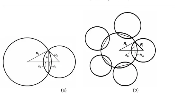
(a) (b)
Fig. 5 Geometry of the grain contacts (flat grain boundary) used for the calculations. (a) Two-grain model. (b) Multi-grain model.
It should be noted that the most complex problem for each time step during computer simulation of skeletel structure evolution is the determination of the neck growth connected to the topological constraints [13].
5. Grain growth
Assume that sintering occurs between two grains with conservation of volume by a single mass transport mechanism. As a matter of fact, sintering will be modeled as a successive overlapping of spherical grains. In order to preserve mass both grains will be allowed to continuously grow due to the neck growth between them. This process will be accomplished by determining and redistributing the (increasing) amount of overlapping volume on the free grain surface area. Fig. 5 shows the phenomenon of undercutting, where it means that the neck profile intersects the profile of the spherical grains. This approach allows a very realistic modeling of the complete 3-D aggregate morphology.
Thus any change in the neck size must have a corresponding functional relation to the volume of material deposited at the neck. In that sense, we will define new methodology for materials redistribution due to the neck growth. Similar methodology was defined by Shaw [14] for the calculation of liquid redistribution during liquid phase sintering.
Due to the neck growth the centers of contacting grains approach each other. The matter which flows out the grain boundary during neck growth must be distributed over the surface. Therefore, to conserve the volume of two-grain model it will be assumed that the material removed from the contacts between two grains of radii R1 and R2 (Fig. 5a) will be evenly distributed over the remainder of the surface of the grains so as to produce two-grain
model with new radii R1New and R2New obtained by numerical calculation of the effective volume of each grain (increased volume overlap will be calculated by comparing the stored initial grain volume with the numerically calculated actual volume). It will be determined from purely geometrical considerations of pairs of successively overlapping grains of arbitrary sizes and the constituting equations for distance reduction. Assuming that the grain boundary is flat, new radii can be found as a first approximation by solving the equations
) 2 , 1 ( ] )
π( 3 4 [ ) π( 3 4
Cup, 3
3− R −V ≤ k=
Rk kNew k ε , (8)
) ) ( ( ) 3 ( π 6
1 2 2 2 2
Cup, h a h h R R a
V k = k + k k = kNew− kNew −
and ε is small enough positive number. Thus, as matter is removed from the grain boundary, the values of neck radius a and radii R1 and R2 increase.
Similar approach will be applied for multi-grain model in which k-th grain has more than one (nk) contacts with its first neighbours (Fig. 5b). The value of its new radius will be computed by solving modified equation (8), i.e.
ε ≤ −
− π( )
∑
]3 4 [ ) π( 3 4 Cup, 3
3 nk
i
ki New
k
k R V
R , where ) ) ( ( ) 3 ( π 6
1 2 2 2 2
Cup,ki hki aki hki hki RkNew RkNew aki
V = + = − − .
A prerequisite for application of the present algorithm is the availability of a sintering law )
(Dki
f given in terms of a rate at which grains approach towards each other, i.e., as a rate of reduction of the pair-wise distance D between grains (Fig. 1). Thus, the simulation method will be based on the concept that sintering law f(Dki) and the transformation (3) can be applied to each pair of contacting grains within the multi-grain model. The current state will be defined by the topology of the skeletal structure, which includes the positions and the sizes of grains and connectivity of all grains with the locations and the sizes of grain boundaries.
6. Energy reduction
The densification process of multi-grain model is accompanied by a decrease of the surface area and the formation of interfaces, so that the surface tension is the driving force for densification and the interface is the resistance to densification. Thus, the whole driving force is now
∑
= i
A
E γi i , (9)
where γi is the interface tension and Ai is the interfacial area.
Let we assume that two spherical grains of radii R1 and R2 have solid-to-solid
contact characterized by the neck radius a and the grain boundary area Agb =πa2 (Fig. 3).
The surface area of k-th grain is Ask =4πRk2−ACupk (k=1,2), where ACupk =2πRkhk is area
of spherical cup (Fig. 5a), thus the surface area of two-grain model will be now As=A1s+As2. The total energy (9) of two-grain model can be now computed as the sum of energies associated with surface and grain boundary areas, i.e.
gb gb s sA A
E=γ +γ , (10)
where γs and γgb are the surface and grain boundary energies. At the neck tip local
equilibrium of the surface tension forces requires that the dihedral angle is maintained. Thus, the dihedral angle (4) is determined by the equilibrium between surface energy and grain boundary energy, i.e. γgb =γs(cosψ1+cosψ2), where ψ1 and ψ2 are determined by
equation (5) for current value of neck radius a and the length of link
) , ( )
( 1 2 1 2
12 d d d C C
o o E
E E
E= −
Δ , (11)
where
) (
4 12 22 s
o R R
E =γ π + (12) is the energy of two separated spherical grains.
For computation of the energy reduction of multi-grain model previous equations for surface and grain boundary areas should be extended. If we assume that k-th grain of radius
k
R has nk solid-to-solid contacts with its first neighbors, as it shown in Fig. 5b, then its grain boundary area will be defined as
) ( gb 2 1
gb
gb ki ki
n
i ki
k A A a
A k π = =
∑
= .The surface area of k-the grain will be
) 2 ( 4 Cup 1 Cup 2
s ki k ki
n
i ki k
k R A A R h
A
k
π
π − =
=
∑
=
.
Total grain boundary and surface areas for multi-grain model of N spherical grains will be now calculated as
∑
= = N k k A A 1 gb gb 2 1 ,∑
= = N k k A A 1 s srespectively. The normalized reduction of the energy (11) can be now computed by the energy equation (10) and the energy of multi separated grains
∑
= = N k k R E 1 2 so γ 4π .
Note that in this computation γs and γgb will be related to the equilibrium dihedral angle (6).
7. Results and discussion
In this section some characteristic simple models as well as planar multi-grain model structures will be presented. They appear to be very helpful in understanding structure transformation during sintering. Simulation of grain coarsening will be realized through four steps simulation algorithm:
• shrink grain connections (neck growth) along skeletal structure; • calculate overlapping volume for each zero-level grain;
• calculate free surface area for each zero-level grain; • increase radius of zero-level grain as to preserve volume.
In this section the sintering behavior of some regular structures will be considered. For simulation we will assume that the neck growth between a single-phase solid grains results in a relative neck size to grain size of about 0.4 after 1 h at sintering temperature, similar to calculated value from conventional sintering models. Initial skeleton structure was perturbed slightly by choosing a small contact area defined by the ratio
) ; , 1 , (
10 4 k i N k i A
Agbki dki= − = ≠ , where Adki =π((Rk+Ri) 2)2 is the initial average
diameteral area for the contact k-i.
The surface bounds one grain, and the grain is constrained to have volume 4πRk3 3(k=1,N). Since the surface has energy proportional to its area, the program evolves the surface toward minimal energy by a gradient descent method under any constraint. For the sake of simplicity, the equilibrium configuration of grains will be calculated under fixed-volume constraint, assuming isotropic surface and grain boundary energies.
(a) (b) (c)
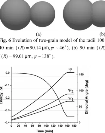
Fig. 6 Evolution of two-grain model of the radii 100 μm and 80 μm due to sintering after (a)
40 min (〈R〉=90.14μm,ψ ~46o), (b) 90 min (〈R〉=91.62μm,ψ ~87o) and (c) 140 min
(〈R〉=99.01μm,ψ ~138o).
Fig. 7 Energy reduction for two-grain model.
7.1. Two-grain model
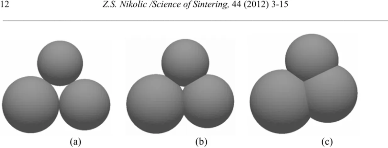
(a) (b) (c)
Fig. 8 Evolution of a three-grain model with the radii 100 μm, 90 μm and 80 μm due to
sintering. (a) Initial structure and after (b) 30 min (〈R〉=90.43μm,〈ψ〉~45o), and (c) 60 min
(〈R〉=93.03μm,〈ψ〉~81o).
Fig. 9 Energy reduction for three-grain model.
7.2. Three-grain model
The elementary sintering process including investigation of the effect of grain rearrangement on grain coarsening and grain growth will be also analyzed by using simple three-grain model shown in Fig. 8. Initially, the topology of the model geometry is represented by three separated spherical grains of different sizes connected by initial point solid-to-solid contacts and a hole between the grains (Fig. 8a) and characterized by the total energy Eo =γs4π(R12+R22+R32). During initial stage of sintering the growth of the sinter bonds from point contacts occur independent of one another since the necks are sufficiently small (Fig. 9). Due to the volume conservation, radii of grains will change too, but their growth will be small. However, further densification is characterized by rapid necks growth and dihedral angles growth. Three circular grain boundaries grow will be then followed by decreasing of hole radius.
7.3. Planar multi-grain mode
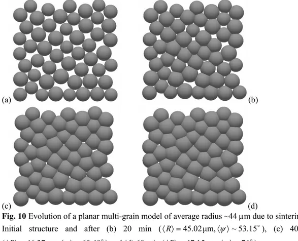
skeletal structure must evolve toward fully continuous interconnected network of solid domains (Fig. 10c). Fig. 10d shows almost completely sintered structure because all grain contacts grow upon sintering and densification of the grain cluster characterized by the pores that are filled or broken into isolated small pores occurs. Fig. 11 visualizes skeletal network assuming that sintering of connected grains follows again the sintering law. The images clearly show the rapid densification of the structure upon sintering.
(a) (b)
(c) (d)
Fig. 10 Evolution of a planar multi-grain model of average radius ~44 μm due to sintering. (a)
Initial structure and after (b) 20 min (〈R〉=45.02μm,〈ψ〉~53.15o), (c) 40 min
(〈R〉=46.37μm,〈ψ〉~69.40o) and (d) 60 min (〈R〉=47.15μm,〈ψ〉~76o).
(a) (b) (c)
Fig. 11 Planar multi-grain network evolution after (a) 20 min, (b) 40 min, (c) 60 min.
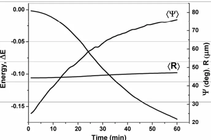
The transformation of the surface into grain boundary decreases the total energy during sintering. The energy decreases with increasing time, and it approaches constant value as the pores shrink and disappear. The grain cluster approaches the final equilibrium shape with the minimal energy, which is determined by the equilibrium dihedral angle.
Fig. 12 Energy reduction for planar multi-grain model.
8. Conclusion
A new simulation model has been applied to model of the three-dimensional grain coarsening during sintering. Sintering is based on a rate law of inter-grain distance reduction. Thestrength during sintering has been determined by the competition among inter-grain neck growth, densification, microstructure coarsening, and topological constraints. In such approach distance reduction, i.e., sintering, leads to overlapping grain volumes which are then redistributed on the remaining free grain surfaces in order to avoid volume defects. This new modeling approach clearly provides valuable information on the skeletal structure evolution of multi-grain model at various process conditions. Additional simulations will be carried out in the near future in order to approach towards real sintering processes. The evaluation of skeletal structure will also be extended in order to determine additional relevant grain properties.
Acknowledgements
The support of the Ministry of Science and Technological Development of Republic of Serbia (Project No. OI172057) is gratefully acknowledged.
References
1. S.-J. Kang, Sintering, Densification, Grain Growth and Microstructure, Elsevier Butterworth-Heineman (2005)
2. W.A. Kaysser, S. Takajo and G. Petzow, Acta Metall. 32, 115-122(1984). 3. G. C. Kuczynski, Met. Trans. AIME. 185 (1949) 169.
4. W. D. Kingery and M. Berg, J. Appl. Phys. 26 (1955) 1205. 5. R. L. Coble, J. Amer. Ceram. Soc. 41 (1958) 55.
7. H.J. Leu, T. Hare and R.O. Scattegood, Acta metall.36 [8] 1977-87(1988). 8. H. E. Exner, Rev. Powd. Met. Phys. Ceram. 1 (1979) 1.
9. K. A. Brakke, Exp Math1 141(1992).
10. Z. Liang, M. A. Ioannidis and I. Chatzis, J Colloid and Interface Sci. 221 13–24(2000). 11. F. Wakai, M. Yoshida, Y. Shinoda, T. Akatsu, Acta Mater. 53 1361-1371(2005). 12. P. Bross and H. E. Exner, Acta Metal., 1979, 27, 1013–1020.
13. Z. S. Nikolic, Submitted to MCM (2011).
14. T. M. Shaw, J. Am. Ceram. Soc., 69 [1] 27-34 (1986).
Са р а: У ј
ј ј ј ј
ј ј ђ .