José Miguel Botica Rodrigues
Licenciatura em Engenharia de Materiais
Production and characterization of magnetic bioactive glass
membranes
Dissertação para Obtenção do Grau de Mestre em Engenharia de Materiais
Orientador: Professor Doutor João Paulo Miranda Ribeiro Borges, Professor Associado com agregação, Faculdade de Ciências e Tecnologia da Universidade Nova de Lisboa Co-orientadora: Doutora Paula Isabel Pereira Soares, Investigadora em Pós-Doutoramento,
Production and characterization of magnetic bioactive glass membranes
Copyright © José Miguel Botica Rodrigues, Faculdade de Ciências e Tecnologia, Universidade Nova de Lisboa.
A Faculdade de Ciências e Tecnologia e a Universidade Nova de Lisboa têm o direito, perpétuo e sem limites geográficos, de arquivar e publicar esta dissertação através de exemplares impressos reproduzidos em papel ou de forma digital, ou por qualquer outro meio conhecido ou que venha a ser inventado, e de a divulgar através de repositórios científicos e de admitir a sua cópia e dis-tribuição com objetivos educacionais ou de investigação, não comerciais, desde que seja dado crédito ao autor e editor.
Acknowledgements
Em primeiro lugar gostaria de agradecer ao Prof. João Paulo Borges, pela confiança que mostrou ao aceitar-me como seu aluno a orientar, por toda a ajuda, conhecimento e profissiona-lismo que me passou durante esta dissertação.
À Doutora Paula Soares, minha co-orientadora por proporcionar um ambiente de trabalho descontraído e por me dar confiança para errar e orientação para aprender com esses erros. A sua mentalidade proactiva e julgamento crítico são duas qualidades profissionais que levo como exemplo e que espero um dia vir a poder alcançar.
Ao Ricardo Matos, que de um dia para o outro passou de desconhecido a colega de trabalho, colega de equipa e amigo. Foi quem me motivou nos dias mais complicados e com quem mais aprendi ao longo desta dissertação.
À Catarina Chaparro e ao Diogo Ramos, por me ajudarem e integrarem no laboratório desde o primeiro dia, por todos os concelhos e por todas as gargalhadas que partilhámos.
À Andreia, à Deneb e à Dona Augusta por toda a paciência, disposição e simpatia sempre com um sorriso enorme capaz de alegrar qualquer pessoa.
Aos colegas de Laboratório Adriana, Cezar, David, Lavadinho, Sofia, Bárbara, Diogo, Ra-faela por me aturarem todos os dias e por tornarem momentos normalmente monótonos em di-vertidos e por me apresentarem problemas novos e estimulantes todos os dias.
Além, Beatriz, Carrêla, Dias, Frederico, Guilherme, Moura, Magda, Moniz, Neto, JP e Sér-gio. Ora “diz-me com quem andas e dir-te-ei quem és” não podia ser mais verdade. Levo comigo, um pouco de todos estes indivíduos extraordinários. Pessoas com um coração gigante, amigos em todo o sentido da palavra e capazes (qualquer um deles) de um dia revolucionar o mundo. Nada me daria mais felicidade que continuar esta viagem ao lado de todos vocês.
Em último lugar e mais importante, não podia deixar de ser para os meus pais, tive muita sorte em ter pais tão dedicados, que sempre me mostraram uma visão abrangente do mundo, sem-pre lutaram e me apoiaram para que eu tivesse todas as oportunidades para ser bem-sucedido. Agradeço-vos por todo o vosso carinho e apoio em todos os dias da minha vida. Agradeço também há minha irmã e irmão, cujos conselhos não posso deixar de contar e que serão sempre dois exem-plos a seguir ao de todo o meu trajeto.
Este trabalho foi financiado utilizando fundos concedidos pela FEDER através do Pro-grama COMPETE 2020 e Fundos Nacionais, através da FCT – Fundação para a Ciência e Tec-nologia, ao abrigo dos projetos POCI – 01-0145-FEDER-007688 e PTDC/CTM-REF/30623/2017.
Resumo
O tratamento do cancro do osso geralmente origina defeitos ósseos com células tumorais residuais que proliferam durante a regeneração óssea. Portanto, é necessária uma estrutura para a regeneração óssea que simultaneamente mate células tumorais residuais. Este projeto visa produ-zir um sistema composto por um vidro bioativo (BAG) e nanopartículas magnéticas (MNPs). Este sistema é altamente bioativo e reabsorvível devido ao vidro bioativo que leva à formação da ca-mada de hidroxiapatite (HA) que faz uma ligação entre o material e o osso. As nanopartículas magnéticas atuam como sementes gerando calor clinicamente relevante, sob aplicação de um campo magnético alternado, para matar ou sensibilizar células tumorais. Em combinação com a liberação de um fármaco citotóxico, este sistema compósito efetivamente irá matar as células do tumor ósseo enquanto fornece a base para a regeneração óssea.
O BAG foi produzido por uma técnica simples de sol-gel assistida por EISA (Evaporation induced self-assembly). Um moinho de bolas foi utilizado para diminuir o tamanho das partículas do BAG e aumentar sua dispersabilidade. Os pós foram caracterizados por SEM (microscopia eletrônica de varrimento), EDS (espectroscopia de dispersão de energia por raios X), e FTIR (Es-pectroscopia por Infravermelho com Transformada de Fourier. As IONPs foram produzidas por co-precipitação química e revestidas com ácido oleico para evitar a agregação e a perda de pro-priedades superparamagnéticas com o tempo. As membranas de PVP/BAG foram produzidas por eletrofiação e os parâmetros foram otimizados de modo a produzir fibras de diâmetros menores, uma vez que isto se traduz numa maior área de superfície e maior bioatividade. Os IONPs foram então incorporados na solução por agitação mecânica.
As membranas eletrofiadas foram reticuladas devido à solubilidade do PVP em água. Para tal foi utilizada a reticulação por UV e térmica, mas apenas a reticulação térmica provou ser bem-sucedida. Neste aspeto, a análise TGA/DSC foi importante para encontrar a temperatura de reti-culação do PVP e forneceu algumas informações sobre a estabilidade térmica das membranas.
As membranas compósitas insolúveis em água foram testadas para aplicação em hiperter-mia magnética e a sua citotoxicidade foi também avaliada. As IONPs provaram ter propriedades superparamagnéticas e uma pequena variação de temperatura foi alcançada para uma amostra de 10 mg de membrana, demonstrando o potencial das membranas compósitas para esta aplicação.
Palavras-chave: Hipertermia magnética, membranas compósitas, nanopartículas de óxido
Abstract
Bone cancer treatment usually originates bone defects with residual tumour cells that can proliferate during bone regeneration. Therefore, a scaffold for bone regeneration that simultane-ously kill residual tumour cells is needed. This project aims at producing a composite system composed of a bioactive glass (BAG) and magnetic nanoparticles (MNPs). This system is highly bioactive and reabsorbable due to the bioactive glass which leads to formation of a hydroxyapatite (HA) layer that bonds to bone. The system is biodegradable at an adequate rate for bone regener-ation. Magnetic nanoparticles act as thermoseeds generating clinically relevant heat under an ap-plied alternating magnetic field to kill or sensitize tumour cells. In combination with release of an anticancer drug, this composite system will effectively kill bone tumour cells whilst providing a base for bone regeneration.
BAG was produced by a simple sol-gel technique assisted by EISA (Evaporation Induced Self-Assembly). Ball milling equipment was used to decrease the BAG particle size and increase its dispersibility. The powders were characterized by SEM (scanning electron microscopy), EDS (energy dispersive x-ray spectroscopy), and FTIR (Fourier Transform Infrared Spectroscopy). IONPs were produced through chemical co-precipitation and coated with oleic acid to avoid ag-gregation and loss of superparamagnetic properties over time. First, PVP/BAG composite mem-branes were produced by electrospinning and the parameters were optimized to produce smaller fibres as it translates into higher surface area and higher bioactivity. IONPs were then incorpo-rated in the solution.
The electrospun membranes were crosslinked due to the PVP water-soluble characteristic. UV and thermal crosslinking were employed, but only thermal crosslinking proved to be success-ful. For this to be successful TGA/DSC was helpful to find the crosslinking temperature and pro-vided information about the thermal stability of the membranes.
Water-insoluble membranes were tested for magnetic hyperthermia application and cyto-toxicity assays were also performed. The IONPs proved to have superparamagnetic properties and a small temperature variation was achieved for a 10 mg membrane sample, which proved the potential of composite membranes for this application.
Keywords: Bioactive glass, bone regeneration, composite membranes, iron oxide
x -Embargado
Contents
Acknowledgements ... v
Resumo ... vii
Abstract ... ix
Contents ... xi
List of figures ... xiii
List of tables ... xv
Abbreviations and symbols ... xvii
1 Motivation and objectives... 1
2 Introduction ... 3
2.1 Scientific context ... 3
2.2 Magnetic Nanoparticles ... 3
2.3 Bioactive glasses ... 5
2.4 Silica-based BAG Polymeric Fibrous Membrane ... 5
2.5 Electrospinning technique ... 6
3 Materials and Methods ... 9
3.1 Synthesis of BAG by Sol-Gel and Ball Milling ... 9
3.2 Synthesis of iron oxide nanoparticles stabilized with oleic acid ... 9
3.3 Fabrication of polymeric fibrous magnetic membranes by electrospinning ... 9
3.4 Characterization ... 10
3.5 Magnetic Hyperthermia assays ... 10
3.6 Bioactivity ... 10
3.7 Cytotoxicity Assays ... 10
4 Results and Discussion ... 11
4.1 Preparation of the precursor materials ... 11
4.2 Production of composite membranes by electrospinning ... 13
4.3 Magnetic hyperthermia Assays ... 26
4.4 Bioactivity Assays in SBF ... 26
4.5 Cytotoxicity Assays ... 27
5 Conclusions and future perspectives ... 30
5.1 Future Perspectives... 31
References ... 32
6 Supporting information ... 34
xii
6.2 Procedure for in vitro cytotoxicity evaluation ... 36 6.3 SEM/EDS elements colour trace of composite membranes (PVP/BAG) ... 37 6.4 SEM/EDS elements colour trace of composite membranes (PVP/BAG/IONPs) ... 38
List of figures
Figure 2.1. Schematic illustration of (A) a single domain magnetic NP with its magnetization pointing to one direction, (B) a group of single domain magnetic NPs aligned along a magnetic field direction, (C) the hysteresis loop of a group of ferromagnetic NPs, and (D) the hysteresis loop of a group of superparamagnetic NPs. (Adapted with permission from [9]. Copyright 2011 American Chemical Society) ... 4 Figure 2.2. Bioactive Glass surface reaction and bone regeneration mechanism [20]. ... 6 Figure 2.3. Schematic illustration of electrospinning setup. ... 7 Figure 4.1. Bioactive glass obtained by sol-gel - EISA process using with a structure-directing agent
(Pluronic F127). ... 11 Figure 4.2. SEM of BAG powders and the respective EDS element spectrum, elements atomic and weight
concentration through EDS. The picture was taken in a 15 KV mode with a backscattered electron detector. ... 12 Figure 4.3. FTIR spectra of BAG and Pluronic F127. ... 13 Figure 4.4. (left) Representative image of a 18% PVP membrane obtained from the design of experiences
study. (right) Corresponding SEM image of the same membrane. The used electrospinning parameters to produce this membrane were 20 kV; 20 cm and 0,1 ml/h. ... 14 Figure 4.5. Sample E2 (a), branched fibres in sample B3 (b), flat fibres in sample D4 (c) and deformed
fibres in sample D4 (d) ... 15 Figure 4.6. Particle size distribution of BAG powders before and after 6 h of ball milling process. ... 16 Figure 4.7. SEM image of fibres produced with PVP 14 wt.% and BAG 14 wt.% in an 85:15 ethanol:water
solution and the following parameters: 20 kV, 20 cm and 0,15 ml/h (sample 18), and the respective size distribution graph. ... 19 Figure 4.8. SEM image of the PVP 14 wt.% and BAG 14 wt.% membrane (top, left), and the respective
EDS elemental map (top, right). Normal and atomic Concentration (wt.% and at.%) quantification on the left down image. Element spectrum on the right down image (carbon and oxygen were ignored) (see Figure 6.2 in supplementary information for complete information of the element colour trace). ... 20 Figure 4.9. DSC/TGA of plain PVP membrane (A) and of composite PVP 14 wt.% and BAG 14 wt.%
membrane. ... 21 Figure 4.10. SEM image of the PVP 14 wt.%, BAG 14 wt.% and 4% IONPs membrane (top, left), and the
respective EDS elemental map. Normal and atomic Concentration (wt.% and at.%) quantification on the left down image. Element spectrum on the right down image (carbon and oxygen were ignored) (see Figure 6.3 in supplementary information for complete information of the element colour trace). ... 22 Figure 4.11. Plain PVP 18 wt.% membranes with different UV crosslinking times after immersed in water. ... 23 Figure 4.12. SEM analysis of the respective PVP 18 wt.% membranes with different UV times in Figure
4.11 after immersed in water. ... 24 Figure 4.13. PVP membrane without treatment before immersion, and PVP membranes with thermal cross-linking of 150ºC with different cross-cross-linking times, after immersion (note: To be able to properly observe the structure different magnifications had to be used for each sample, therefore the magnification used should not be considered). ... 24
xiv
Figure 4.14. PVP, PVP BG, PVP BG IONP´s membranes observed on SEM, before and after crosslinking
at 150 ºC for 24 h, and after 24 h immersion in ultra-pure water and drying. ... 25
Figure 4.15. Temperature variation (ºC) from magnetic hyperthermia assays for IONPs in 4% aqueous solution, 10 and 20 mg of 14 wt.% PVP, 14 wt.% BAG, and 4 wt.% IONPs. ... 26
Figure 4.16. SEM images of the PVP 14 wt.% and BAG 14 wt.% after 6, 12, 24, 48 and 72 h immersion in SBF. ... 27
Figure 4.17. Vero cell viability (%) after indirect exposure to the different electrospun membranes. PVP corresponds to plain PVP 18 wt.% membrane; BAG corresponds to composite PVP 14 wt.% and BAG 14 wt.% membrane; and IONPs correspond to composite PVP 14 wt.%, BAG 14 wt.% and IONPs 4 wt.% and respective dilutions 1 and 2 (factor 2). ... 28
Figure 6.1. Schematic planning for cytotoxicity assays. ... 36
Figure 6.2. SEM/EDS elements colour trace attached to Figure 4.8. ... 37
List of tables
Table 4.1. Average diameter of electrospun fibres obtained from PVP and BAG mixtures. Results are presented as average diameter ± standard deviation calculated from at least 30 measures. Samples codes (A1 to E8) correspond to a set of electrospinning parameters, which can be consulted in Table 6.1 in supplementary information.. ... 14 Table 4.2. Influence of flow rate in the average fibre diameter (nm) of samples with PVP 14 wt.% and BAG
14 wt.% in an 85:15 ethanol:water solvent. ... 17 Table 4.3. Influence of applied voltage in the average fibre diameter (nm) of samples with PVP 14 wt.%
and BAG 14 wt.% in an 85:15 ethanol:water solvent. ... 18 Table 4.4. Influence of the needle to collector distance (cm) in the average fibre diameter (nm) of samples
with PVP 14 wt.% and BAG 14 wt.% in an 85:15 ethanol:water solvent. ... 18 Table 6.1. Electrospinning parameters tested using different concentrations of BAG in an 18 wt.% PVP
solution in ethanol. ... 34 Table 6.2. Set of electrospinning parameters tested using a solution of 14 wt.% PVP and 14 wt.% BAG
Abbreviations and symbols
AMF Alternating magnetic field ATR Attenuated total reflectance BAG Bioactive glass
Ca Calcium CT Chemotherapy
DMSA Dimercaptosuccinic acid DTA Differential thermal analysis EDS Energy dispersive spectroscopy EISA Evaporation induced self-assembly F127 Pluronic F127
Fe3O4 Magnetite
FTIR Fourier transform infrared spectrometer H Magnetic field
HA Hydroxyapatite HT Hyperthermia IONPs Iron Oxide NPs
MBG Mesoporous bioactive glass MNPs Magnetic nanoparticles MS Magnetization saturation
MRI Magnetic resonance image Na Sodium NP Nanoparticle O Oxygen OA Oleic acid P Phosphorous P123 Pluronic 123
PEO Poly(ethylene oxide) PVA Poly(vinyl alcohol) PVP Polyvinylpyrrolidone RT Radiation Therapy SAR Specific absorption rate SBF Simulated body fluid
xviii SEM Scanning electron microscopy
Si Silicon
TEOS Tetraethyl orthosilicate TEP Triethylphosphate
TGA Thermogravimetric analysis UV Ultraviolet
1 Motivation and objectives
Cancer is a global problem with an increasing incidence every year. In particular, bone cancer has a high incidence and related death in young groups. Bone is also the third most frequent site of metastasis, after lung and liver, which reflects the high incidence of bone injuries. Bone cancer treatment usually originates bone defects with residual tumour cells that can proliferate during bone regeneration. Therefore, a scaffold for bone regeneration that simultaneously kill residual tumour cells is needed.
In the Biomaterials group the research is focused in developing new composite materials for biomedical applications. One of the main research areas is the development of multifunctional magnetic nanoparticles for cancer theranostic through a combination of magnetic hyperthermia, controlled drug delivery and diagnostic by magnetic resonance imaging. On another research line, the group has focused on the development of composite materials for bone tissue engineering. More recently, a PhD student started to develop a 3D composite system composed of bioactive glasses (BAGs), magnetic nanoparticles and a capsule of electrospun fibres. This system is highly bioactive and resorbable due to the bioactive glass which leads to formation of a hydroxyapatite layer that bonds to collagen fibrils. The system is biodegradable at an adequate rate for bone regeneration. BAGs are greatly known for their bioactive properties and ability to induce bone and tissue regeneration. They have also been electrospun into fibrous membranes, with suitable diameters and great surface area that further improve their bioactivity when compared to BAG in the form of powder, so a BAG fibrous membrane represents a very good candidate to incorporate the MNPs for hyperthermia treatments. A biocompatible polymer like Polyvinylpyrrolidone (PVP) may be used to help properly produce these membranes, through electrospinning tech-nique. Magnetic nanoparticles act as thermoseeds generating clinically relevant heat under an applied alternating magnetic field to kill or sensitize tumour cells. In combination with release of an anticancer drug, this composite system will effectively kill bone tumour cells whilst providing a base for bone regeneration.
In this thesis the main objective is to produce by electrospinning a composite membrane composed of bioactive glass, a biocompatible and biodegradable polymer with magnetic nano-particles incorporated. This composite membrane should be bioactive and be suitable for mag-netic hyperthermia application, making a proof of concept of a material that can aid the regener-ation of bone and simultaneously kills cancer cells by magnetic hyperthermia in the tumour site. To achieve such objective, the following topics were addressed:
Study the influence of electrospinning parameters in the production of polymer/bi-oactive glass fibres;
Optimize bioactive glass concentration (as the bioactive glass will be majorly re-sponsible for the bioactive properties of the composite) in the fibres;
Successfully incorporate magnetic nanoparticles in the composite membrane, to properly induce magnetic hyperthermia treatment
Study the biomedical application of the produced composite membranes by per-forming cytotoxicity studies, bioactivity studies and magnetic hyperthermia stud-ies.
2 Introduction
2.1 Scientific context
Current cancer treatments are based on surgery, radiotherapy (RT), chemotherapy (CT) and biological therapies [1]. Radiotherapy uses high-energy rays or particles to kill cancer cells, but most bone cancers are not easily killed by radiation, and high doses are needed. This can damage nearby healthy tissues and structures like nerves and blood vessels. Consequently, radiotherapy is not used as a main treatment for most bone tumours, but it is used to slow the growth of cancer cells generated due to bone metastases[2]. Chemotherapy consists in using systemic drugs to kill cancer cells all over the body. This treatment option is limited for larger tumours (like most bone cancers) because the treatment is not localized and healthy cells are very sensitive to current chemotherapy drugs, therefore it is not a very effective method for bone cancer treatment [1], [2]. An alternative treatment that has been studied these past years is hyperthermia (HT) with the help of magnetic nanoparticles (MNPs). Magnetic HT works as a calculated increase of tem-perature in the human body, within the range of 40-44 ºC, by applying an electromagnetic stimu-lus on magnetic nanoparticles that act like thermoseeds. Their efficiency can be measured by the ability to reach and accumulate on the tumour area [3]. This temperature increase leads to tumour cell death which are more sensitive to heat than normal tissues. Clinical application of hyperther-mia is not established as a single treatment modality but as a way to improve chemotherapy and radiotherapy results, when applied in repetitively short intervals [4]–[6].
In order to adequately perform localized magnetic hyperthermia in an affected area it is important to find new alternatives that ensure the presence of NPs in the tumour region without any cytotoxic effect. A biocompatible, bioactive membrane with trapped NPs may represent a good alternative as it avoids the leakage of NPs in the targeted area.
2.2 Magnetic Nanoparticles
Magnetic Nanoparticles have been widely studied for biomedical applications as contrast agents for magnetic resonance imaging (MRI) and as hyperthermia agents for cancer treatment. [20]. There are different types of MNPs, generally composed of pure metals, metal alloys or metal oxides. From all of those, Iron Oxide NPs (IONPs) specifically Fe3O4 (magnetite) have shown
superior biocompatibility and stability and are the most commonly used magnetic NPs for bio-medical applications. MNPs physicochemical properties are size-dependent and in proper condi-tions are able to generate heat when subjected to an alternating magnetic field (AMF), due to energy losses during the demagnetization process, which is crucial for HT [7].
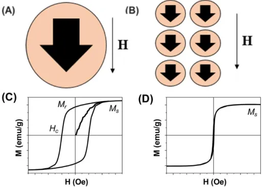
A ferromagnetic NP with size smaller than 20 nm often contains a single magnetic domain with one collective magnetization direction (Figure 2.1 A). Once these NPs are placed under an external magnetic field (H), their magnetization directions can be aligned along the field direction to achieve magnetic saturation with overall magnetization reaching the saturation magnetization (MS) (Figure 2.1 B and C). When the size of a ferromagnetic NP is reduced to a level where the
thermal energy is comparable to the magnetic anisotropy energy, this NP is magnetically unstable and is said to be superparamagnetic[8]. A group of superparamagnetic NPs can be easily
magnet-4
ized (with large susceptibility) to reach MS, but they have no coercivity and remnant
magnetiza-tion (Figure 2.1 D). Magnetic NPs in the superparamagnetic state have much weaker magnetic dipole interactions and therefore are readily stabilized and dispersed in liquid media [9].
Figure 2.1. Schematic illustration of (A) a single domain magnetic NP with its magnetization pointing to one direction, (B) a group of single domain magnetic NPs aligned along a magnetic field direction, (C) the hysteresis loop of a group of ferromagnetic NPs, and (D) the hysteresis loop of a group of superparamag-netic NPs. (Adapted with permission from [9]. Copyright 2011 American Chemical Society)
The frictions caused by the physical rotation of a NP, Brownian relaxation, and the mag-netization reversal within the NP, Néel relaxation, lead to the loss of magnetic energy and the generation of thermal energy. The heating power of these NPs is directly related to the ferromag-netic hysteresis area and frequency of the alternating magferromag-netic field [10]. To ensure better thermal effects under the common hyperthermia conditions, magnetic NPs should have small coercivity, large susceptibility, and high MS. The NP heating efficiency is measured by the specific
absorp-tion rate (SAR, W.g-1). For practical therapeutic applications with minimized side effects, it is
critically important to obtain optimum heating efficiency to reach the desired hyperthermia tem-perature at 41-44 ºC [9]. MNPs stability in physiological conditions can limit their desired per-formance. The size of MNPs is the crucial factor determining their uptake of target cell and elim-ination from the body. For example MNPs which have the diameter size larger than 200 nm are retained in the spleen and liver while particles of smaller sizes than 10 nm are rapidly removed via renal clearance [3]. In order to avoid that, several reports on MNPs coating with molecules like oleic acid (OA) or dimercaptosuccinic acid (DMSA) have been successful on stabilizing the MNPs and preventing their aggregation as they create repulsive forces, mainly stereo chemical repulsions, that compensate the attractive magnetic and van der walls forces [4] [7].
2.3 Bioactive glasses
Bioactive glasses are a class of biomaterial with increased interest along the years. BAGs form a hydroxyapatite (HA) layer on the biomaterial when implanted in the human body through glass dissolution. HA is the inorganic part of human bone and therefore BAGs are able to bond and form a stable interface with bone tissues while being biodegradable and stimulating bone regeneration [11]–[13]. The first form of BAG was Larry Hench’s 45S5 Bio-glass (commercial name) with a 45 wt.% SiO2, 24.5 wt.% CaO, 24.5 wt.% Na2O, and 6.0 wt.% P2O5 composition
(wt.% represents the molecular weight percentage), produced by a melt quenching synthesis and presented in the late 1960´s [11]. Since then, many different compositions of bio-glass and their in vitro and in vivo behaviour has studied.
There are different techniques available in literature to produce BAG. Melt quenching is a process that requires temperatures up to 1300-1400 ºC and only bio glasses produced with less than 60 wt.% of SiO2 show bioactivity in in vivo conditions. Above that level of wt.% of SiO2 the
material does not develop a HA layer and does not bond to bone or soft tissues. The major alter-native process to melt quenching is the Sol-Gel technique which is a lower temperature process. This process enables the production of a larger range of bio glass compositions, up to 90 wt.% SiO2, with similar biological response to the ones produced by melt quenching [14], [15]. Sol–
gel BAGs exhibit higher rates of apatite phase formation, faster bone bonding and excellent deg-radation and resorption properties [16].
In order to enhance bioactivity, both composition and structure are important in BAGs de-rived from sol-gel. A better control of properties like specific surface area and pore volume can increase the bioactive response, so it is important to control the overall porosity and pore structure of the material. In 2004, Yan et al. [13] pioneered the synthesis of mesoporous BAGs with SiO2
-CaO-P2O5 system, breaking ground for the development of BAGs with superior bioactivity
com-pared to conventional melt-derived and sol-gel materials.
2.4 Silica-based BAG Polymeric Fibrous Membrane
In order to induce proper bone regrowth, the materials that compose the scaffold must be biocompatible and the scaffold itself should provide proper environment to stimulate new bone production. Allowing cells and blood vessels to spread through the scaffold is very important and for that, a certain level of macro/microporosity is necessary.
Silica-based BAGs are able to bond and create a stable interface with living bone tissue without promoting inflammation or toxicity [17]. Their main advantage to be used in bone regen-eration is their high bioactivity, which allows BAGs to create an apatite-like phase, similar to the inorganic part of the bone, when in contact with physiological fluids. Also the degradation of these BAGs have shown osteoconductive properties, which means that bone tissue grows on BAG surface [18], [19]. The reaction at BAG surface when in contact with body fluids is illustrated in Figure 2.2 and described elsewhere [20].
In order to produce BAGs with high surface area and high porosity at low temperatures, both crucial for high bioactivity, the sol-gel process has been widely used and studied along the years. During the sol–gel process, the gelling stage occurs at room temperature. Bioactive glasses can be made by sol–gel processing, thus facilitating the incorporation of organic and biological
6
molecules within the network, or even cells within silica matrices [18]. Moreover, sol–gel pro-cesses can be combined with supramolecular chemistry of surfactants, resulting in a new highly ordered mesoporous material for biomedical applications. Yan et al. [13] compared conventional sol-gel BAGs to new sol-gel BAGs with non-ionic triblock co-polymers Pluronic 123 and Plu-ronic 127 assisted by Evaporation Induced Self-Assembly (EISA). The EISA process is based on preferential evaporation of the solvent which progressively enriches the concentrations of non-volatile solution constituents and finally ordered mesophase occurs. The surfactant molecules self-organize into micelles that link the hydrolysed silica precursors trough the hydrophilic com-ponent and self-assemble to form an ordered mesophase[21]. After gelling, drying and surfactant calcinations, bioactive mesoporous glasses (MBG) were obtained. It was also revealed by scan-ning electron microscopy (SEM) analysis that the bioactivity of MBG strongly depends on MBG composition. 80S15Ca5P MBG showed a bigger bioactivity than 70S25C5P, 60S35C5P, 100S by decreasing order [13].
Figure 2.2. Bioactive Glass surface reaction and bone regeneration mechanism [20].
Among the different BAG structures produced, MBGs of nanofibrous structure present two advantages: at microscopic level the ultrathin fibres have highly specific surface areas and at macroscopic scale, due to their long length, the nanofibres can be assembled in 3D membranes with an interconnected macroporous network [22], [23].
2.5 Electrospinning technique
Nano fibrous membranes can be obtained by several techniques such as drawing, templates synthesis, phase separation, self-assembly and electrospinning [22]. From these, electrospinning stands out as being the most accessible, versatile, low cost and relatively fast compared to the previous mentioned techniques.
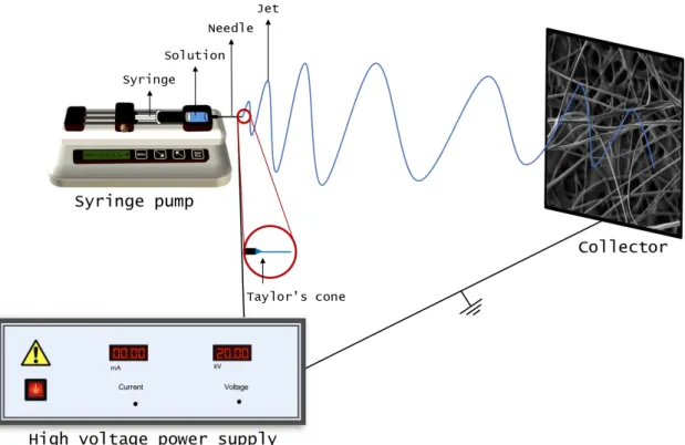
Electrospinning is a broadly used technology for fibre formation which uses electrical forces to produce nano or micro polymer fibres. In a conventional electrospinning setup (Figure 2.3), the solution passes through a needle and a high voltage is applied. At a critical voltage the repulsive force of the charged particles within the solution, overcomes the surface tension of the solution and a jet erupts from the tip of the needle towards a grounded collector. The fibres mor-phology will depend on the solution properties (viscosity, conductivity and surface tension); flow rate of the solution, voltage applied to the needle, distance between the needle and collector and
finally temperature and humidity. Electrospinning requires a viscoelastic solution that has the ability to stretch under high elongation forces, while resisting break-up, so the use of a polymer like PVA, PVP or PEO is often needed in order to guarantee electrospun fibres [24].
3 Materials and Methods
3.1 Synthesis of BAG by Sol-Gel and Ball Milling
BAG powders were produced by a simple sol-gel process assisted by EISA using tetraethyl orthosilicate (C4H20O4Si, TEOS, Sigma-Aldrich), calcium nitrate (Ca(NO3)2, VWR Chemicals),
and triethyl phosphate ((C2H5O)3PO, TEP, Fluka) as inorganic precursors, Pluronic F127 (Mw
12000 Da, Sigma-Aldrich) as the structure-directing agent, and ethanol (Sigma-Aldrich, 99.8%) as solvent. The amount of inorganic precursors was calculated in order to obtain a ratio of 80Si:15Ca:5P (representing the molar fraction of Si, Ca and P).
The process was adapted from the work of Yan [13]. First, 1.84 g of F127 were dissolved in a 60 g of ethanol. 6.7 g TEOS, 0.73 g TEP and 1.4 g Ca(NO3)2 were added in this order, with
a 1 ml of 0,5 M HCl solution being added at last. The final solution was kept at room temperature under magnetic stirring for 24 h. To completely dry the gel, the resulting sample was kept at 60 ºC until total evaporation of ethanol. The final mesostructured product was shattered by a ball milling technique using the Planetary Mono Mill “pulverisette 6”, Fritsch for 6 h. The powders were uniformly grinded by planetary ball mill, with zirconia balls with 1500 RPM in grinding periods of 30 min, to avoid the equipment overheating. At last, the powders were left to dry and were prepared. Measures of the powder were taken before and after 6 h of grinding.
3.2 Synthesis of iron oxide nanoparticles stabilized with oleic acid
IONPs were produced by chemical co-precipitation technique as described by Matos et al. [4]. Iron chloride tetrahydrate (FeCl2.4H2O, 2.5 mmol, Sigma-Aldrich) and iron chloride
hexahy-drate (FeCl3.6H2O, 5 mmol, Sigma-Aldrich) were mixed in ultrapure water (Míli-Q) followed by
addition of an ammonium solution (NH4OH at 25 %, 10 ml, Panreac) to precipitate the IONPs in
the absence of oxygen (by bubbling N2). The amount of oleic acid was calculated as a percentage
of the NPs mass [7], followed by ultrasonic bath during 3 h to ensure the coating of all IONPs. To remove the excess of oleic acid, the suspension was in dialysis until pH 7.
3.3 Fabrication of polymeric fibrous magnetic membranes by
electro-spinning
The electrospinning solution was prepared using polyvinylpyrrolidone (PVP, Mw 1 300 000 Da, Sigma-Aldrich) as an auxiliary polymer to adjust the solution viscosity and to promote fibre formation [25]. A 14 wt.% BAG and 14 wt.% PVP (both relative to ethanol mass) solution was prepared using magnetic stirring and ultrasounds to uniformly disperse the BAG particles. The high voltage source used for the electrospinning process was a Glassman EL 30kV, which was connected to the metal needle through the positive pole, and the ground with the col-lector. The infuser pump, which had a constant flow rate, was a KDS100 KD Scientific. The solution was always carefully introduced into a 1 ml syringe, with an internal diameter of 4.50 mm. As for the metal needles used, a 21 G gauge needle was always used in this work. The fibres were collected on an aluminium foil, with the collector being motionless. All equipment was wrapped in an acrylic box for a better control over the environmental parameters of the process,
10
with the natural humidity of the laboratory being around 30-40%. Fibres production was opti-mized by varying the flow rate, applied voltage and distance to the collector at controlled humid-ity and temperature (Table 6.1 in Supplementary information). Furthermore, IONPs were added to the ethanol/PVP/BAG system to achieve a 4 wt.% IONPs (wt.% relative to the polymer mass). PVP is highly soluble in water and therefore not suitable for biological applications. There-fore, PVP membranes were crosslinked by thermal crosslinking with temperatures of 150 ºC, 175 ºC and 200 ºC for times of 5, 10, 15, 20 and 24 h using the Nabertherm High Temperature Furnace HTCT 01/16/P330 LC011H6SN and also by UV radiation crosslinking using a Vilber Lourmat™ Biolink™ BLX UV Crosslinkerfor 1, 2, 3, 4, 5 and 6 h.
3.4 Characterization
Scanning electron microscopy (SEM) was performed using a Carl Zeiss Auriga SEM equipment to analyse fibre morphology. The samples were coated with a thin layer of gold and palladium. Additionally, Energy Dispersive Spectroscopy (EDS) using Oxford Instruments EDS was performed to detect the presence of BAG and iron elements in the fibres. FTIR spectra of the samples were obtained using a Nicolet 6700–Thermo Electron Corporation Attenuated Total Re-flectance-Fourier Transform Infrared spectrometer (ATR-FTIR). Measurements were performed in freeze-dried samples in the range of 480–4000 cm−1 with a resolution of 2 cm−1. Thermograv-imetric analysis (TGA) and differential thermal analysis (DTA) studies were carried out using a Thermal Analyzer NETZSCH STA 449 F3 Jupiter® at a rate of 10 ºC.min−1 in a N
2 atmosphere.
3.5 Magnetic Hyperthermia assays
Magnetic hyperthermia measurements were obtained using the equipment NanoScale Bio-magnetics, DM100 Series. The heating capacity of 10 mg of the membranes immersed in 1 ml of ultrapure water with incorporated IONPs were tested. Measurements were performed for 10 min maintaining the magnetic flux density at 24 kA.m-1 and the frequency at 418.5 kHz.
3.6 Bioactivity
Simulated body fluid (SBF) was prepared according to the procedure given by Kokubo et al. [26], [27]. Square samples of 1 cm2 and 5 mg were immersed in 20 ml of SBF for 6, 12, 24,
48 and 72 h. During this time, the samples were placed in an incubator at 37 ºC to mimic physio-logical temperature. After the stipulated time, samples were removed and washed with Millipore water and dried in air. The samples were then observed in SEM.
3.7 Cytotoxicity Assays
To evaluate the cytotoxicity of the membranes, the assays were performed according to standard ISO-10993 Biological evaluation of medical devices, Part 5: Tests for in vitro cytotoxi-city. The assays were performed using the extract method and Vero cells (monkey renal epithelial cells), as described elsewhere [4] and in the section 6.2 of supplementary information in detail.
4 Results and Discussion
4.1 Preparation of the precursor materials
The main objective of this thesis was to produce and characterize magnetic bioactive glass membranes and to test their application in magnetic hyperthermia. For that, two main precursor materials were used: iron oxide nanoparticles and bioactive glass.
4.1.1 Iron oxide nanoparticles
The IONPs used to produce the fibrous membrane were synthetized using a co-chemical precipitation technique that was previously optimized by the research group [28]. Due to the NPs low stability in aqueous solutions, they were coating with oleic acid. These NPs were extensively characterized in another published work [4]. For some contextualization, we present the most relevant results for this dissertation. Uncoated IONPs are spherical and have an average diameter of 9.4 ± 1.9 nm. The coating of these NPs with oleic acid did not show any influence in particles size or morphology. IONPs crystallinity was studied by XRD showing the presence of magnetite characteristic peaks with a crystalline cubic structure. Again, the presence of the surfactants did not alter the crystalline structure of the IONPs.
4.1.2 Bioactive glass 80Si15Ca5P
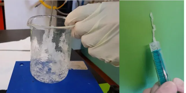
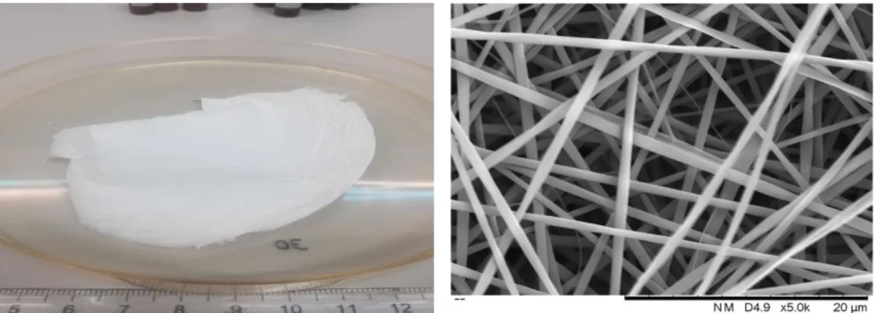
In this work BAG was produced by sol-gel technique assisted by EISA using Pluronic F127 as the structure-directing agent. The amount of inorganic precursors was calculated to obtain a ratio of 80Si:15Ca:5P (representing the molar fraction of Si, Ca and P). Figure 4.1 illustrates the obtained BAG which behaves like a gel and can be easily extruded by a syringe.
Figure 4.1. Bioactive glass obtained by sol-gel - EISA process using with a structure-directing agent (Plu-ronic F127).
12
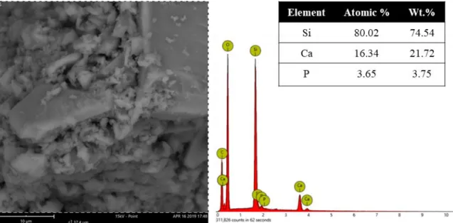
The first step to characterize the obtained BAG was to confirm its atomic composition, i.e., to confirm if the final molar ratio was 80Si:15Ca:5P. For that, BAG powder was observed with SEM and EDS not only to analyse its structure but also to evaluate the composition elements and atomic concentration of BAG. Figure 4.2 represents SEM image of as-produced BAG and the respective EDS analysis through the element spectrum, the atomic and weight % of each element.
In the SEM image BAG powder shows different particle sizes. The powder does not seem to present any kind of porosity, because unlike most common BAG, this one is not sintered to remove the structural agent. The EDS element spectrum confirms that the as-synthesized BAG is composed by Si, Ca, P, O and C. To determine the weight concentration of Si, Ca and P (the elements responsible for the BAG properties), the elements O and C were ignored. Consequently, an 80,02 % of Si, 16.34 % of Ca and 3.65 % of P atomic composition was confirmed which is very similar to the desired ratio of 80Si:15Ca:5P.
Figure 4.2. SEM of BAG powders and the respective EDS element spectrum, elements atomic and weight concentration through EDS. The picture was taken in a 15 KV mode with a backscattered electron detector.
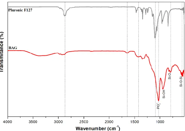
To analyse the chemical composition of BAG powders, FTIR analysed was performed. Figure 4.3 shows the comparison of BAG and Pluronic F127 spectrum. In BAG spectrum, the band at 566 cm-1 is assigned to the Si-O-Si rocking mode, while the band at 788 cm-1 is attributed
to the SiO4 bending vibration. The band at 956 cm-1 may be attributed to the Si-OH bending
vibration but it is unclear due to a similar peak in Pluronic F127. Moreover, the band at 1025 cm -1 is associated with the PO
43- asymmetric stretching mode (characteristic of BAG), while the band
at 1090 cm-1 is usually assigned to the Si-O-Si stretching vibration, however F127 also has a
similar band in the same wavenumber. The band in 1340 cm-1 is an O-H in-plane bending
char-acteristic of F127. Finally, the band at 1645 cm-1 is assigned to the stretching vibrations of surface
Figure 4.3. FTIR spectra of BAG and Pluronic F127.
4.2 Production of composite membranes by electrospinning
Initially, a study was carried out to evaluate the parameters effect on the electrospinning process (applied voltage, flow rate and needle-collector distance) to determine the ideal parame-ters for the production of PVP membranes. This work was made in parallel by a PhD. student using the design of experiences and the response surface methodology to obtain the smaller fibre diameter. In this work, the smaller diameters are considered the most suitable because smaller fibre diameter leads to higher surface area which is directly related to a higher bioactivity/biodeg-radation. Figure 4.4 shows the 18 wt.% PVP membrane produced in the referred study and the respective SEM image with an average fibre diameter of 668 ± 191 nm. The electrospinning rameters 20 kV, 20 cm and 0,10 ml/h were taken into consideration while choosing the test pa-rameters for the composite membranes of PVP and BAG.
4.2.1 Composite membranes of PVP and BAG
Based of the best set of parameters obtained from the previous study, the composite mem-branes of PVP and BAG were produced using a PVP concentration of 18 wt.% with different BAG concentrations (1; 2; 3; 4; and 5 wt.%). The main purpose of this step was to evaluate BAG effect on fibres morphology and electrospinning conditions. For this set of experiences 2 flow rates (0.2 and 0.4 ml.h-1); 2 applied voltages (15 and 20 kV) and 2 different needle-collector
dis-tances (15 and 20 cm) were used with controlled humidity and temperature during 15 min of fibre deposition. The average fibre diameters were obtained from SEM images using ImageJ Software, by measuring at least 30 single fibres from each collected image. The average fibre diameters are
14
presented in Table 4.1 and the complete information (correspondence between sample code (A-E) and tested parameters) can be consulted in Table 6.1 in supplementary information.
Figure 4.4. (left) Representative image of a 18% PVP membrane obtained from the design of experiences study. (right) Corresponding SEM image of the same membrane. The used electrospinning parameters to produce this membrane were 20 kV; 20 cm and 0,1 ml/h.
Table 4.1. Average diameter of electrospun fibres obtained from PVP and BAG mixtures. Results are pre-sented as average diameter ± standard deviation calculated from at least 30 measures. Samples codes (A1 to E8) correspond to a set of electrospinning parameters, which can be consulted in Table 6.1 in supple-mentary information. (The blank spots represent samples that were not possible to properly visualize with this technique)
Sample Average diameter
(nm) Sample Average diameter (nm) Sample Average diameter (nm) A1 C1 336 ± 72 E1 365 ± 51 A2 C2 426 ± 128 E2 360 ± 56 A3 483±144 C3 426 ± 107 E3 368 ± 125 A4 457 ± 104 C4 474 ± 148 E4 374 ± 60 A5 354 ± 69 C5 325 ± 64 E5 421 ± 67 A6 349 ± 101 C6 E6 337 ± 53 A7 368±87 C7 405 ± 121 E7 A8 349 ± 115 C8 399 ± 77 E8 B1 383 ± 94 D1 350 ± 63 B2 353±90 D2 373 ± 95 B3 531 ± 175 D3 442 ± 87 B4 433 ± 115 D4 409 ± 108 B5 411 ± 131 D5 347 ± 70 B6 342 ± 82 D6 446 ± 95 B7 490 ± 141 D7 308 ± 45 B8 396 ± 107 D8 412 ± 94
The number of samples with different electrospinning parameters is too low to determine the ideal conditions. However, it is possible to say that the parameters 15 kV, 15 cm and 0,2 ml/h (samples A1, B1, C1, D1, E1) produced, on average, smaller diameters with a smaller standard
deviation, which means higher uniformity. No significant differences were found samples with different BAG wt. % using the same electrospinning conditions. This indicates that it is possible to increase BAG concentration without significantly affect the average fibre diameter.
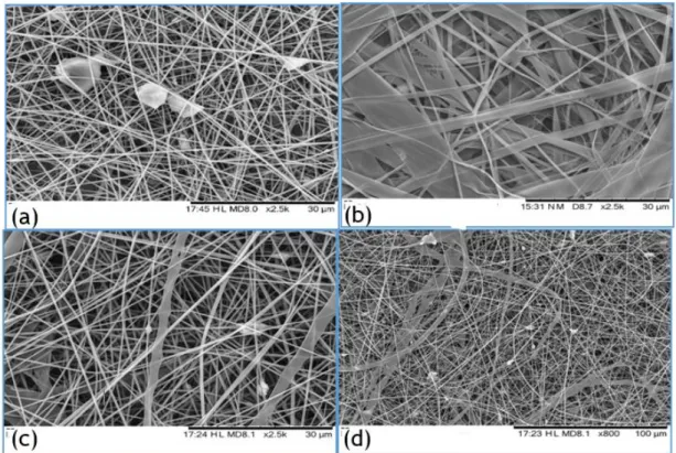
However, some defects were found in the composite fibres with the increase of BAG con-centration. Most samples presented fibres with regular shape, but some dispersed BAG particles (Figure 4.5 (a)) were visible in some areas of the membrane. Moreover, were also found branched fibres (Figure 4.5 (b)), plane fibres (Figure 4.5 (c)), and deformed fibres (Figure 4.5 (d)). The humidity percentage was lower than 30 % for all these samples. In a low humidity environment, the ejected solvent can evaporate too quickly and cause the phenomenon responsible for these irregular fibres described in literature [29]. Higher applied voltages (around 20 kV) can also cause some electrical instability that could also explain these deformations [29]. In addition, BAG par-ticles are not very well dispersed in the membrane and there is a big discrepancy between parpar-ticles sizes as it is observed in Figure 4.5 (a) and (d).
Figure 4.5. Sample E2 (a), branched fibres in sample B3 (b), flat fibres in sample D4 (c) and deformed fibres in sample D4 (d)
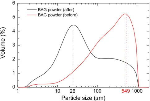
From this analysis, it was concluded that the humidity levels should a slightly higher, above 30 % to avoid fibre defects. Moreover, BAG concentration can be increased at least up to 5 wt.%; however, particles should have uniform sizes and should be more dispersed within the membrane. The higher dispersity of particles in the membrane can be explained by particle size. After complete drying, BAG powders were manually grinded using a grinder and mortar. Using this procedure, the obtained BAG particles had a particle size of around 549 μm. This powder was further incorporated into the electrospun solution. However, after these initials attempts of pro-ducing the electrospun membranes, it was obvious through SEM analysis that the BAG particles
16
size had to be reduced, to promote the homogeneous dispersion of BAG in the membrane. To reduce particle size a ball mill process was used for 6 hours. The particle size analyser proved the particle size reduction from 549 μm (before) to 26 μm (after 6 h), which is represented in Figure 4.6. Although some aggregates are still present, the average particle size was greatly reduced to a factor of around 20 times its initial size.
Figure 4.6. Particle size distribution of BAG powders before and after 6 h of ball milling process.
After realizing that BAG content in the electrospun solution could be increased, a solution of 18 wt.% PVP with 9 wt.% BAG was prepared and electrospun. Using an optical microscope, the presence of electrospun fibres were confirmed. Since a content of 9 wt.% of BAG was easily dispersible in the 18 wt.% PVP solution, a test was made by doubling BAG concentration. The prepared solution with PVP and BAG at 18 wt.% each was extremely hard to disperse and with a unsuitable viscosity for electrospinning. Therefore, both PVP and BAG concentration was brought down to 14 wt.% each. This was an easily dispersible solution but when tested in elec-trospinning, the solvent (ethanol) was evaporating too quickly, not allowing a proper fibre depo-sition. Consequently, instead of forming a membrane, this solution produced a 3D structure. Since this was not the purpose of this thesis, the solvent was changed to a mixture of ethanol:water in a ratio of 85:15 (v/v). Since the concentrations and solvent were changed, the electrospinning pa-rameters were again optimized to obtain fibres without defects and with the smallest diameter. The set of experiments, as well as the studied parameters can be found in and Table 6.2 in sup-plementary information. The criteria for choosing the flow rates (0.05; 0.15; 0.25 ml/h) was based on the droplet accumulation on the needle tip. These droplets are to avoid in an ideal electrospin-ning process, as they can cause big defects on the membrane if the droplet is ejected. If the droplet is not ejected from the needle, this represents a waste of solution and proves the non-ideal effi-ciency of the process. The applied voltage and needle–collector distance were kept at 15 and 20 kV and 15 and 20 cm, respectively, with intermediate values of 18.3 kV and 18 cm.
The fibres diameters were measured in the same way as before and the results were ar-ranged to facilitate the comprehension of the influence of each process parameter. Table 4.2
1 10 100 1000 0 1 2 3 4 5 6 549
Volume (%)
Particle size (
m)
BAG powder (after) BAG powder (before)
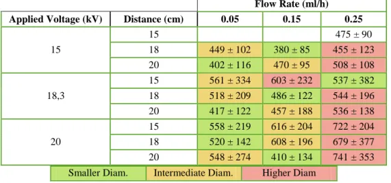
shows the influence of flow rate in the average fibre diameter (nm) of samples with PVP 14 wt.% and BAG 14 wt.% in an 85:15 ethanol:water solvent. At a flow rate of 0.25 ml/h a droplet on the needle tip starts to form, which causes instability of the ejected fibres and can explain why there is a tendency to produce higher fibre diameters. Using lower flow rates (0,05 ml/h) smaller fibres are obtained when compared to a flow rate of 0.15 ml/h. Higher flow rates mean more material being ejected with slower drying time, prior to reaching the collector and lower stretching forces, thus explaining higher diameters. Although 0.05ml/h seems the best flow rate for this work pur-pose, it takes too long to produce a 100 mg membrane. With a 0.15ml/h flow rate that times decreases 3 times, and combined with the 20 kV, 20 cm or 15 kV and 18 cm it can produce good quality fibres with smaller diameter and smaller standard deviation (around 410 ± 134 and 380 ± 85 nm, respectively).
Table 4.2. Influence of flow rate in the average fibre diameter (nm) of samples with PVP 14 wt.% and BAG 14 wt.% in an 85:15 ethanol:water solvent. (The diameters were compared from left to right with the re-spective colours)
Flow Rate (ml/h) Applied Voltage (kV) Distance (cm) 0.05 0.15 0.25
15 15 475 ± 90 18 449 ± 102 380 ± 85 455 ± 123 20 402 ± 116 470 ± 95 508 ± 108 18,3 15 561 ± 334 603 ± 232 537 ± 382 18 518 ± 209 486 ± 122 544 ± 196 20 417 ± 122 457 ± 188 536 ± 138 20 15 558 ± 219 616 ± 204 722 ± 204 18 520 ± 142 608 ± 196 679 ± 377 20 548 ± 274 410 ± 134 741 ± 353 Smaller Diam. Intermediate Diam. Higher Diam
Table 4.3 shows that influence of applied voltage in the average fibre diameter (nm) of samples with the same precursor solution. A lower applied voltage usually is responsible for smaller diameters and lower standard deviation. However, this subject is a little controversial, as researchers have proven that voltage does influence fibre diameter, but the level of significance varies with solution viscosity and needle-collector distance [30]. This can explain what happens on the samples with 0.15 ml/h and 20 cm, where the diameters increase with the increase of ap-plied voltage. Besides, with 15 kV a droplet on the needle tip was also formed which can represent a significant waste of electrospinning solution. Finally, Table 4.4 shows the influence of the nee-dle to collector distance (cm) in the average fibre diameter of samples with the same precursor solution. With the increase of needle to collector distance from 15 cm to 20 cm, fibres become thinner, as the ejected solvent has enough time to evaporate before reaching the collector and more time to stretch the fibre.
From this study it can be concluded that for the solution of PVP 14 wt.% and BAG 14 wt.% in an 85:15 ethanol: water solvent the flow rate of 0.05 ml/h produces the smallest average fibre diameter. However, it takes too long to produce a membrane compared to higher flow rates of 0.15 ml/h and 0.25 ml/h. Of these two, 0.15 ml/h shows the smallest average fibre diameter com-pared to the ones from 0.25 ml/h. In terms of distance from needle to collector, 20 cm is the best
18
parameter (compared to 15 and 18 cm) to produce smallest fibre diameter, as well as it decreases the standard deviation, which means a more homogeneous membrane. This is due to the ejected solution having more time to elongate. Regarding the applied voltage, 15 kV produces smaller fibres, but most of the electrospinning solution is not properly ejected, as the voltage is not enough to overcome the surface tension of the solution, and it accumulates on the tip of the needle in form of droplets. The droplets may cause defects on membrane if ejected to the collector, and if not ejected it ends up being material wasted. For this reason, an applied voltage of 15 kV is too be avoided. Fixing the flow rate on 0,15 ml/h and the distance in 20 cm, it is clear that a 20 kV voltage produces better fibres than 18.3 kV.
Table 4.3. Influence of applied voltage in the average fibre diameter (nm) of samples with PVP 14 wt.% and BAG 14 wt.% in an 85:15 ethanol:water solvent.
Applied Voltage (kV) Flow Rate (ml/h) Needle-Collector
Distance (cm) 15 18.3 20 0.05 15 561 ± 334 558 ± 219 18 449 ± 102 518 ± 209 520 ± 142 20 402 ± 116 417 ± 122 548 ± 274 0.15 15 603 ± 232 616 ± 204 18 380 ± 85 486 ± 122 608 ± 196 20 470 ± 95 457 ± 188 410 ± 134 0.25 15 475 ± 90 537 ± 382 722 ± 204 18 455 ± 123 544 ± 196 679 ± 377 20 508 ± 108 536 ± 138 741 ± 353
Table 4.4. Influence of the needle to collector distance (cm) in the average fibre diameter (nm) of samples with PVP 14 wt.% and BAG 14 wt.% in an 85:15 ethanol:water solvent.
Needle-collector distance (cm) Applied Voltage (kV) Flow Rate (ml/h) 15 18,3 20
15 0.05 449 ± 102 402 ± 116 0.15 380 ± 85 470 ± 95 0.25 475 ± 90 455 ± 123 508 ± 108 18.3 0.05 561 ± 334 518 ± 209 417 ± 122 0.15 603 ± 232 486 ± 122 457 ± 188 0.25 537 ± 382 544 ± 196 536 ± 138 20 0.05 558 ± 219 520 ± 142 548 ± 274 0.15 616 ± 204 608 ± 196 410 ± 134 0.25 722 ± 204 679 ± 377 741 ± 353
For these reasons, the parameters 0,15 ml/g flow rate; 20 cm distance and 20 kV applied voltage, were the chosen for producing the membranes as depicted in Figure 4.7. The membrane produced with these parameters had a average fibre diameter of 410 ± 169 nm with (what appears to be) small nuclei of BAG within. Some reports like [31] have achieved similar sizes in their studies. Most of fibres measured have diameters between 300 and 400 nm, however there are still
some fibres with over 700 nm, which increases the standard deviation and may be attributed to the high voltage (20 kV) used in the process. Compared to the 18% PVP membranes in the DOE referred above, these PVP, BAG membranes had smaller diameters for similar parameters. This may be attributed to the smaller PVP concentration (14 wt.%) in the PVP, BAG membranes, as it has been shown that solutions with lower polymeric concentration produce smaller fibre diam-eters [31].
Figure 4.7. SEM image of fibres produced with PVP 14 wt.% and BAG 14 wt.% in an 85:15 ethanol:water solution and the following parameters: 20 kV, 20 cm and 0,15 ml/h (sample 18), and the respective size distribution graph.
After the optimization of the electrospinning parameters, the composition of the obtained membranes was analysed. First, with the help of EDS equipment coupled to SEM, the atomic concentration and element maps were analysed to examine the presence of BAG within the fi-brous scaffold. Figure 4.8 shows the SEM image of the PVP 14 wt.% and BAG 14 wt.% mem-brane and the respective EDS elemental map. Analysing SEM image it is clear the presence of round shaped BAG particles trapped and mixed in the fibrous scaffold. These nuclei are majorly composed of silica, with presence of calcium and phosphorous. Ca and P also seem to be dispersed within the polymeric fibres. EDS also provides the quantification of both normal concentration and atomic concentration of the elements present on the spectrum (Figure 4.8 down right image). The atomic composition, 74.84 wt.% of Si, 17.64 wt.% of Ca and 7.66 wt.% of P is very close to the desired 80Si15Ca5P composition.
Thermogravimetric analysis was carried out to study the thermal stability of PVP and the composite membranes. TGA of the PVP membrane (Figure 4.9 A) showed the first mass loss below 100 ºC corresponding to the 56 ºC exothermic peak in the DSC trace. This is associated with water adsorption and other alcohol by-products of the condensation reactions. A small mass loss continues until 340 ºC occurs, and the exothermic peak 185 ºC is believed to be related to the PVP reticulation, as it has been reported to be around between 150 ºC and 200 ºC [31]. Only at around 340 ºC PVP starts decomposing until around 460 ºC where only a residual mass percentage is left. Analysis of the thermal stability of composite membranes in Figure 4.9 B shows a first mass loss of 5.11 % until around 120 ºC corresponding to the exothermic peak at 59 ºC, which is attributed to the water adsorption and other alcohol by-products of the condensation reactions. A new mass loss of 122 % occurs from 120 ºC until around 380 ºC. From 150 ºC to 200 ºC the mass loss can be attributed to the PVP crosslinking, as it has been shown to happen around this area
20
[31]. From 200 ºC to 340 ºC the mass loss is attributed to the decomposition of F127. This de-composition is reported to continue until 580 ºC in [32], but at 340 ºC the PVP in the membrane also starts decomposing very fast until 480 ºC. From there, a slow decomposition of residual PVP and F127 is believed to happen.
Figure 4.8. SEM image of the PVP 14 wt.% and BAG 14 wt.% membrane (top, left), and the respective EDS elemental map (top, right). Normal and atomic Concentration (wt.% and at.%) quantification on the left down image. Element spectrum on the right down image (carbon and oxygen were ignored) (see Figure 6.2 in supplementary information for complete information of the element colour trace).
Figure 4.9. DSC/TGA of plain PVP membrane (A) and of composite PVP 14 wt.% and BAG 14 wt.% membrane.
From this analysis, it is possible to determine the PVP crosslinking temperature which is around 190 ºC for plain PVP membranes and a little bit higher for PVP+BAG membranes. Also, PVP and F127 components can be eliminated (if wanted) with temperatures around 500 ºC.
4.2.2 Composite membranes of PVP, BAG and IONPs
Previously synthesized IONPs were incorporated in the electrospinning solution by adding a known concentration to the PVP 14 wt.% BAG 14 wt.% solution in a concentration of 4 wt.% relative to the PVP mass. This solution was mixed by mechanical stirring for about 20 min. The following solution was electrospun with 20 kV; 20 cm; 0,15 ml/h with 35% relative humidity and 25 ºC.
The same analysis process was applied on the electrospun PVP/BAG/IONPs membrane. In Figure 4.10 a sample of the composite membrane was observed in SEM and EDS. The addition of IONPs seems to not influence the morphology of the fibres (Top, left). The EDS elemental map (top, middle) shows the presence of BAG components (Si, Ca, P) but also the clear presence of iron (top, right) from the IONPs added. The quantification of normal and atomic concentration (bottom left) is merely indicative of the presence of iron and does not translate to the overall normal and atomic concentration of the membrane. The small size of NPs (around 10 nm) makes it impossible to observe with this SEM equipment. Transmission Electron microscopy (TEM) analysis would be more suitable to observe the IONPs.
22
Figure 4.10. SEM image of the PVP 14 wt.%, BAG 14 wt.% and 4% IONPs membrane (top, left), and the respective EDS elemental map. Normal and atomic Concentration (wt.% and at.%) quantification on the left down image. Element spectrum on the right down image (carbon and oxygen were ignored) (see Figure 6.3 in supplementary information for complete information of the element colour trace).
4.2.3 Thermal and UV crosslinking of PVP membranes
PVP is soluble in aqueous solutions, and consequently it is unsuitable for biomedical ap-plications. To make PVP water-insoluble membranes, the polymer must be crosslinked. PVP crosslinking has been successfully reported by thermal treatment [31] and by UV treatment [33], with both stimulus enabling different polymer chains to link through a covalent or ionic bond, promoting changes in the polymer physical properties.
For the UV crosslinking, a UV light was used. Plain PVP 18 wt.% membranes were sub-mitted to different UV times: 30 min, 1, 2, 3, 4, 5 h. The samples were then immersed in water with an immediate change of white colour membrane to a transparent film (Figure 4.11). This indicates that the fibrous structure of the membrane was lost and that after UV crosslinking the membranes were still water-soluble.
However, from Figure 4.11 it is not clear what happens to the membrane structure after immersion, so samples (after immersed) were analysed on SEM (Figure 4.12) to study the struc-ture of the membrane with the UV crosslinking time. With the SEM analysis we see that samples with increased UV exposure have more tendency to completely lose their desired fibrous struc-ture, turning it into a film. Already with 30 min and 1 h, the differences are clear and with 2 h UV it is no longer possible to observe any fibrous structure.
Figure 4.11. Plain PVP 18 wt.% membranes with different UV crosslinking times after immersed in water.
As for the thermal crosslinking, samples were initially crosslinked with temperatures of 200 ºC and 175 ºC and 1.5 and 10 h. However, the temperature control was difficult, and samples were scorched (turned into dark brown) and fibres lost their morphology and structure. The tem-perature was decreased to 150 ºC for 5, 10, 15, 20 and 24 h. With this treatment conditions the membrane was not scorched and when immersed in water, did not dissolve. Through SEM anal-ysis, the structure and morphology of the fibres were evaluated. Figure 4.13 shows SEM images of plain PVP membranes after thermal crosslinking. Comparing a plain PVP membrane before and after crosslinking at 150 ºC at different times after immersion, confirms the maintenance of the fibrous structure for times above 20 h. At 5 h, the structure is practically fully destroyed, while after 10 h it starts getting possible to see a fibrous look alike structure. After 15 h a fibrous struc-ture is maintained but the fibres are still affected by the water absorption. After 20 h and 24 h the differences are very small, and a fibrous structure is fully maintained.
24
Figure 4.12. SEM analysis of the respective PVP 18 wt.% membranes with different UV times in Figure 4.11 after immersed in water.
Figure 4.13. PVP membrane without treatment before immersion, and PVP membranes with thermal cross-linking of 150ºC with different cross-cross-linking times, after immersion (note: To be able to properly observe the structure different magnifications had to be used for each sample, therefore the magnification used should not be considered).
Based on these results, composite membranes were crosslinked at 150 ºC for 24 h. Figure 4.14 shows SEM images of plain PVP, PVP/BAG and PVP/BAG/IONPs membranes before and after thermal crosslinking. The crosslinked membranes were immersed in ultra-pure water to test their solubility, and unlike the non-crosslinked membranes, they did not dissolve instantly. They were then immersed in water for 24 h and dried at 40 ºC. In Figure 4.14, we can see their micro-structure through SEM images. Comparing these images with the respective membranes before immersion in water, we can observe some swelling of the fibres. This swelling change the fibres morphology and dimension which might change the membranes bioactivity and mechanical prop-erties, as they are directly influenced by the surface area and consequently the diameter and shape of the fibres. This swelling capacity should be quantified by measuring the amount of water that the membrane can absorb in an established period of time. Also, with this analysis it is not clear if the membranes are fully water insoluble. The membranes seem to not dissolve in the naked eye, but there is the possibility that some part of the membrane is lost to the solvent. A study measuring the mass of the solvent and of the membrane before and after immersion should provide this information about the membrane properties.
Figure 4.14. PVP, PVP BG, PVP BG IONP´s membranes observed on SEM, before and after crosslinking at 150 ºC for 24 h, and after 24 h immersion in ultra-pure water and drying.
26
4.3 Magnetic hyperthermia Assays
Magnetic hyperthermia assays were performed to evaluate the heating capacity of the IONPs alone and IONPs in the PVP/BAG membranes, in the presence of an alternating magnetic field. All assays were performed during 10 minutes with a magnetic flux density of 300 Gauss and a frequency of 418.5 kHz. Figure 4.15 represents the temperature variation for assays on a 1 ml aqueous solution with 4% IONPs. Three assays were performed, giving an average tempera-ture variation of 22 ºC ± 1.8ºC. Samples of 10 and 20 mg of a PVP/BAG/IONPs composite mem-brane were tested (Figure 4.15). The concentration of IONPs in the memmem-brane (4% of the polymer mass) is lower than in the aqueous solution (4% of the solution), therefore lesser NPs are present on the membrane samples, therefore lower temperature variation were expected as confirmed with average temperature variations of 0.7 ± 0.15 ºC for 10 mg of membrane and 2 ± 0.36 ºC for 20 mg of membranes.
Figure 4.15. Temperature variation (ºC) from magnetic hyperthermia assays for IONPs in 4% aqueous solution, 10 and 20 mg of 14 wt.% PVP, 14 wt.% BAG, and 4 wt.% IONPs.
The increase of heating capacity (1.3 ºC) with the double of membrane mass (and conse-quently double IONPs) is also stated. If the normal body temperature is considered to be 37ºC, a temperature variation of 0.7 ºC (10 mg membrane) and 2 ºC (20 mg membrane) would not be enough to reach the desired therapeutic temperature for magnetic hyperthermia on cancer tissue (between 40 and 44 ºC), without more membrane mass or IONPs concentration. Nevertheless, the incorporation of IONPs in a polymeric bioactive glass membrane was successful and added a new property (potentially useful for magnetic hyperthermia treatment) to the membrane.
4.4 Bioactivity Assays in SBF
The bioactivity assays are performed on materials as a reference for further evaluating in vivo bioactivity using animals or other sources. The thickness, coverage, form of apatite and time
0 5 10 15 20 25 20 mg membrane 10 mg membrane
dT
(º
C)
IONPs 4% in watertaken to deposit apatite are often estimated. Figure 4.16 shows the evaluation of a PVP 14 wt.% and BAG 14 wt.% composite membrane in different immersion times on SBF. BAG particles observed in non–immersed membrane are thought to start forming apatite, as this is the BAG purpose in the composite. However, with increasing immersion times it is not possible to observe these particles anymore. From 6 to 12 h we can observe a slight difference where a film starts forming after 12 h immersion in SBF. This film formation may be due to the apatite formation and after 24 h this effect is aggravated; however, this is not coherent in the following images.
To further analyse the formation of apatite on the membrane, FTIR and DRX analysis should be used to chemically confirm the apatite formation. The soluble species of silica, phos-phate and calcium concentrations in SBF before and after immersing the membrane should also be measured to assess the SBF uptake of the species. This measurement could give a more precise estimative of the time taken by the membrane to dissolute each of the species and consequently the time taken to form apatite on the membranes.
Figure 4.16. SEM images of the PVP 14 wt.% and BAG 14 wt.% after 6, 12, 24, 48 and 72 h immersion in SBF.
4.5 Cytotoxicity Assays
In order to ascertain the biocompatibility of the PVP membranes with BAG and IONPs, the potential cytotoxic effect of these membranes on Vero cells was evaluated using the extract method (ISO standard 10993-5). The results are shown in Figure 4.17 which expresses cell via-bility in %. The cell viavia-bility (%) was determined following the procedure in supplementary in-formation. The assays were performed for an extract concentration of 16 mg/ml with an uncer-tainty of 5 %. Two dilutions (factor 2) were performed for each membrane and 5 replicas for each sample. The control medium shows a cell viability around 100% and was used as reference for the following samples. All pure PVP samples revealed no cytotoxicity with cell viability (%) of 92 % (for normal concentration) and 96 % (for dilution 1) and 91 % (for dilution 2), proving the expected biocompatibility of the PVP.
![Figure 2.2. Bioactive Glass surface reaction and bone regeneration mechanism [20].](https://thumb-eu.123doks.com/thumbv2/123dok_br/15588299.1050264/24.892.137.764.442.649/figure-bioactive-glass-surface-reaction-bone-regeneration-mechanism.webp)