Damage analysis of carbon/epoxy plates after drilling
Luís Miguel Pereira Durão, João Manuel R. S. Tavares, António Gonçalves de Magalhães, António Torres Marques, António Paulo M. Baptista
1. INTRODUCTION
The use of laminate composites in structures is under a considerable increase. The advantages of their use are related with a considerable weight reduction and consequent improvement of dynamic characteristics, in the case of aeronautics, automobile, railway and naval industries. Some applications of these materials in sports are already well known, like cycling, motor sports or golf, just to mention some. Drilling is a widely used technique as it is usually needed to assemble components in more complex structures. According to Stone and Krishnamurthy (1996), in the aircraft industry, about 60% of part rejections come from drilling-associated delamination.
Drilling is a complex process characterized by the existence of “extrusion” and cutting mechanisms, the former performed by drill chisel edge that has null or very small linear speed and the latter by the existence of rotating cutting lips at a certain speed.
As composites are non-homogeneous and anisotropic, drilling raises specific problems that can affect parts strength and fatigue life, Persson (1997), Hamdoun (2004). Typical damages after drilling are push-out delamination at exit side, peel-up at entrance side, intralaminar cracking, fibre/matrix debonding and thermal damage. Due to their abrasiveness, composites drilling cause high tool wear, leading to the need of frequent tool changes that affect the production cycle. From all these problems, delamination is the most serious as it severely reduces the load carrying capacity of laminated composite structures and must be avoided, Bader (1994). Delamination is a defect that occurs in interlaminar regions, that is to say, in the contact plan between adjacent layers,
so it depends not only on fibre nature, but also on resin type and adhesive properties. Delamination mechanisms are divided according to the laminate region where it occurs, exit or entrance, respectively called push-out and peel-up.
Peel-up is caused by the cutting force pushing the abraded and cut materials to the flute surface. Initially, the cutting edge of the drill will abrade the laminate. As drill moves forward it tends to pull the abraded material along the flute and the material spirals up before being effectively cut. This action creates a peeling force upwards that tends to separate the upper laminaes of the plate (fig. 1). This peeling force is a function of tool geometry and friction between tool and workpiece, Hocheng and Dharan (1995).
Push-out is a consequence of the compressive thrust force that the drill always exerts on the workpiece. The laminate under the drill tends to be drawn away from the upper plies, breaking the interlaminar bond in the region around the hole. As the drill approaches the end of the laminate, the uncut thickness becomes smaller and the resistance to deformation decreases. At some point, the loading exceeds the interlaminar bond strength and delamination occurs, before the laminate is totally penetrated by the drill (fig. 2). A different tool geometry that lowers thrust force can reduce delamination, Hocheng and Dharan (1995).
Temperature rise on the part should be limited, in order to avoid thermal damages. Heat that develops due to tool-part friction during drilling can also facilitate delamination by matrix softening.
Fibre/matrix debonding is observed along the machined hole walls and is characterized by the existence of torn away fibres off the matrix by the action of drill cutting edges. Intralaminar cracks are also reported in literature as a typical damage mode occurring in a composite plate after drilling, Hocheng and Puw (1992).
Tool wear is a consequence of composite abrasiveness and low thermal conductivity that causes tool heating superior to what is normally observed in the drilling of metallic materials. In carbon-epoxy drilling, 50% of the energy is absorbed by the tool and the remainder is absorbed almost equally by the workpiece and chips Abrate (1997).
Several drilling techniques, based in an adequate selection of tool geometry and cutting parameters, have been proposed with the aim to minimize delamination around the hole. Piquet (2000) completed an experimental analysis of drilling damage in carbon/epoxy plates using special drills. Peel-up delamination can be reduced with the use of a small rake angle - 6º - preventing the first ply from lifting up and tearing off. A greater number of cutting edges, three to six, increase the contact length between tool and part, facilitating heat removal. Point angle of 118º is necessary for the main cutting edges and then 70º for the minor cutting edges. Chisel edge dimensions have a direct relation with the onset of delamination, so it is necessary to be as reduced as possible. Normally, the non-cutting edge represents 20% of the drill diameter. Pre-drilling neutralize the chisel edge effect, having a result similar to the non-existence of chisel edge.
Persson (1997) studied the consequence of hole machining defects on strength and fatigue life of carbon/epoxy composite laminates. For that purpose, two traditional tools - PCD drill and Dagger drill – were compared with the orbital drilling method. Orbital drilling is a patented method by NOVATOR®, developed by Zackrisson, Persson and Bäcklund at the Department of Aeronautics of Kungl Tekniska Högskolan (KTH) in Sweden. The hole is machined, axially and radially, by rotating the cutting tool about its own axis as well as eccentrically about a principal axis while feeding through the laminate. Some advantages of this method are referred by the authors in Persson (1997) when compared to traditional hole machining methods: elimination of a stationary tool centre, thus substantially reducing axial force; reduction of the risk of tool clogging, as
the tool diameter is smaller than the diameter of the hole, allowing cut material to be easily removed and efficient cooling of tool and hole surface; possibility of using one tool diameter to machine several holes diameters; precision of the hole determined by tool positioning and not by tool precision itself, reducing tool costs.
Tsao and Hocheng (2004) conducted an analysis of the effect of drill geometry using three different drills and analysis of variance. In this study, the authors concluded that feed rate resulted to be more important as a cause for delamination than cutting speed, although drill geometry also showed to have some importance on the occurrence of this damage. The use of candle-stick or saw drill resulted in less delamination when compared to twist drill damage.
Won and Dharan (2002) conducted drilling tests on aramid and carbon fibre-reinforced composite laminates using carbide drills. During these tests, thrust force and torque were monitored to establish the contribution of chisel edge cutting force to total thrust force at different speeds. A ratio of thrust force acting on the chisel edge to total thrust force was established. Results show that independently of hole diameter, chisel edge contribution to total thrust force was between 60 and 85%, increasing at higher feed rates. They also concluded that thrust force increases with feed rate.
The importance of a pilot hole has been evidenced by Tsao and Hocheng (2003) that have measured a 25-50% reduction on thrust force during drilling when using a pilot hole, showing that the use of this strategy is an indication that delamination-free drilling is achievable. The pilot hole diameter should be able to cancel the chisel edge effect which is largely responsible for the extrusion mechanism that occurs during laminate drilling.
The extent of surface layer microgeometric variations caused by a manufacturing process is usually quantified by surface roughness parameters. Surface roughness is
influenced by tool geometry, cutting parameters, machine stiffness and chip formation mechanisms. Surface characterization parameters provide a basis for assessing the surfaces produced by a machining process. There are numerous parameters to describe surface texture. The most commonly used is the average surface roughness – Ra – which is defined as the arithmetic average of the absolute values of the deviations of the surface profile height – z –from the mean line within the sampling length –l, Ramulu (1998). Roughness effect on tensile, compressive and flexure resistance of composites machined parts was analysed and no significant effect was found, Ramulu (1998). Mechanical properties are essentially independent of machining method with insignificant variations. Eriksen (1999) concluded that it is possible to set up guidelines for cutting parameters like feed rate, cutting speed, tool radius and fibre orientation, but these relations will differ from the theoretical ones applicable to metal cutting.
2. DAMAGE MODELS
The critical thrust force for the onset of delamination has been the object of several studies, based on linear elastic fracture mechanics – LEFM. The simplest in its formulation and more used, is the model presented by Hocheng and Dharan (1995). In this model, the critical load at the onset of crack propagation can be calculated by the following equation: 2 1 2 3 ) 1 ( 3 8 ⎥ ⎦ ⎤ ⎢ ⎣ ⎡ − = υ π G Eh F Ic crit (1),
where GIc is the interlaminar fracture toughness in Mode I, E is the elastic modulus of the unidirectional plate, h is the uncut thickness in mm and ν is the Poisson ratio of the material.
Another model was presented by F. Lachaud (2001). In its work, the authors developed a model where the contact between drill and plate was considered as a distributed load. In their model the Dij coefficients (bending stiffness) have been calculated by using relations of laminate plate theory. The critical value of the thrust force is then:
( )
(
)
2 1 ' 8 3 1 8 ⎥ ⎦ ⎤ ⎢ ⎣ ⎡ − = D D D G F Ic crit π (2),where D and D’ are respectively: ) 3 4 2 3 ( 8 1 22 66 12 11 D D D D D= + + + (3), and 3 2 ' D11 D22 D12 D66 D = + + + (4).
The model was tested experimentally. The experiment consists in applying a perpendicular load to a carbon/epoxy plate that was pre-drilled to a given depth. The load was applied by a stationary drill used as a punch, without rotation and with a feed rate of 1 mm/min. For plates with less than 7 plies the results were in good correlation with the model.
Hocheng and Tsao (2003) developed analytical models to predict the critical thrust force at the onset of delamination for different drill geometries, like saw drill, Brad drill, core drill and step drill. Results were compared with existing model developed for twist drill (eq. 1). Each drill is considered separately and the results show the need of different equations for each tool geometry.
Jung (2005) proposed a new formulation for the critical thrust force to propagate delamination, in the case of angle-ply laminates. In their model, the authors have considered the existence of twisting and mid-plane extension of the delamination zone.
They concluded that the tendency of variation of the critical thrust force with lamination angle is non-linear. When this angle is equal to 33.5º, the critical force is the highest. After laminate holes are drilled, it is important to establish criteria that can easily compare the delamination degree of various processes, even though they can only be applied to composites with the same lay-up regarding orientation and number of plies. Chen (1997) proposed a comparing factor that enables the evaluation and analysis of delamination extension in laminated composites. That ratio was called the Delamination Factor (Fd) and it was defined has the quotient between the maximum delaminated diameter (Dmax) and the hole nominal diameter (D),
D D
Fd = max (5).
Mehta (1992) have suggested a different ratio with the same purpose, named Damage Ratio (DRAT), defined as the ratio of Hole Peripheral Damage Area (DMAR) to Nominal Drilled Hole Area (AAVG), i.e.,
AVG MAR
RAT D A
D = (6).
This hole damage evaluation method is based on the existence of damage images from C-Scan and pixel counting of the digitized damaged area, as described in Chen (1997), or from digitized radiographs, Mehta (1992).
Tsao and Hocheng (2005) used ultrasonic techniques and computerized tomography for the evaluation of delamination damage in carbon/epoxy composite plates. The photographs obtained from the use of those techniques allow the measurement of delamination extension. The authors concluded that feed rate is an important factor in delamination onset, as higher feeds cause higher thrust force, thus increasing the risk of damage occurrence around the hole.
3. EXPERIMENTAL WORK
3.1 MATERIALS AND TOOLS
In order to perform the experimental work, a carbon/epoxy plate was made from pre-preg with a stacking sequence of [(0/-45/90/45)]4s, giving the plate quasi-isotropic properties. The laminate was cured, in a hot plate press, under 3 daN/cm2 pressure and 140ºC for one hour, followed by air cooling. Each ply has a nominal thickness of 0.125 mm. The final thickness of the plate was 4 mm.
Drilling of the plates was carried out in a OKUMA MC-40VA machining centre. Monitoring of axial thrust force (Fz) during drilling was executed with a Kistler 4782 dynamometer associated to a multichannel amplifier and a PC for data collection. The workpiece was clamped to the dynamometer prior to drilling.
All the drills used were in tungsten carbide, K20 grade, with a diameter of 6 mm. All parts were drilled without the use of a sacrificial plate. Four types of drill were compared: twist drill, Brad drill, Dagger drill and step drill. All these tools are shown in fig. 3. Twist drill (fig. 3a) is a tool with a standard geometry. The twist drill was used in two conditions: first without a pilot hole and then with pilot holes of 1.1, 2.3 and 3.5 mm diameter. The intention of the several pilot hole diameters was to observe the reduction of the maximum thrust force achieved and to quantify the decrease in delamination around the hole when this alternative drilling strategy is used. First diameter – 1.1 mm – was selected to be close to the diameter of the chisel edge of the twist drill – 1.08 mm. Comparison of delamination results for each pilot hole will help on the selection of a recommendable pilot hole diameter. Brad drill (fig. 3b) is a special edged drill firstly designed for cutting wood, with edges in sickle shape, that causes the tensioning of the fibres prior to cut, thus enabling a ‘clean cut’ and a less irregular machined surface. Dagger drill (fig. 3c), although appropriate for carbon/epoxy drilling,
need to have enough space on the exit side, due to its small point angle – 30º - which increases the drill displacement needed to complete a through hole. Step drill (fig. 3d) has two diameters dividing the drilling operation in two stages. The intention is to reduce the maximum thrust force during drilling, thus reducing the risk of delamination. The main drawback of this tool is its large first diameter (3.4mm).
Cutting parameters were selected with the advice of tools manufacturers. The feed was 0.05 mm/rev for all drills and the speed was 4200 rpm for the others, except for Dagger drill. The use of the higher cutting parameters for Dagger drill showed unsatisfactory results in terms of hole quality. With a feed rate of 0.10 mm/rev peel-up delamination occurred which was considered unacceptable and with a speed of 4200 rpm the hole was eccentric. After consulting tool manufacturer, it was decided to use lower parameters for this drill, with a speed of 200 rpm and a feed of 0.5 mm/rev, even though the chip ap was not constant for all the drills. The pilot holes were drilled with a speed of 4200 rpm and a feed of 0.03 mm/rev for every diameter.
All results in this paper represent the average of five tests under the same conditions. As there is a variation of thrust force during one drill rotation due to the mechanics of the process itself, this force was always averaged over one spindle revolution. The results of this average will be referred as thrust force.
3.2. DEVELOPMENT OF THRUST FORCE DURING DRILLING
The development of axial thrust force during drilling operation follows a typical curve, as it is shown in fig. 4. At the beginning there is a rise of the force values, corresponding to the contact between drill tip and part. As the drill contact diameter increases from chisel size to its nominal value, there is a quick rise of the thrust force. The value becomes reasonably steady during a period of normal drilling with the drill
cutting the material at nominal diameter. The period has a duration corresponding to the perforation of all the plate thickness. As the drill tip reaches the exit side of the plate, the thrust force decreases rapidly towards zero.
3.3 ENHANCED RADIOGRAPHY
Radiography is a well recognized and documented non-destructive method that is applied in industry for assessment of the soundness of materials and components. The technique is based on different absorption of penetrating radiation by the object being inspected. Due to differences in density and variation of thickness of the part, as well as in absorption characteristics caused by changes in composition, different portions of a test piece absorb different amounts of penetrating radiation. Unabsorbed radiation passing through the part can be recorded on a film or photosensitive paper, Evans (1996), Tsao and Hocheng (2005). Defects that are oriented perpendicularly to the beam are more prone to be detected.
Radiography is suitable on the detection of delaminations only if a contrasting fluid like di-iodomethane – CH2I2, methylene iodide– from Merck is used. To obtain a radiographic image, the contrasting fluid – di-iodomethane – is poured into an appropriate container and the plate is immersed for one and a half hour in a dark chamber. After required time elapsed, the plates are carefully cleaned to remove all fluid stains and placed over a film. For these plates, the exposition time was 0.25 sec. Developed films were used for the measurement of delaminations around the hole. Fig. 5 shows some radiographies from holes made with twist, Brad and Dagger drills.
3.4 COMPUTATIONAL VISION
The use of Computational Vision has the purpose to reckon from the images obtained by radiography, information regarding damaged area or diameter. This process has the advantage of reducing operator dependence to measure the necessary dimensions, thus increasing results reliability. An existing processing and image analysis platform was used, Tavares (2000), Tavares (2002). This platform turned possible the use of some standard Computational Vision techniques, Awcock (1995), Jain (1995), Schalkoff (1989) to accomplish the required values regarding damage measurement.
For radiographic images, the processing and analysis sequence starts with the manual selection of the interest zone, with the objective of reducing computational time. The second step was the pre-processing of the sub image by a smoothing filter to reduce sudden changes of intensity thus reducing existing noise. Next step was the segmentation of the interest areas on the smoothed image. As in many cases, this segmentation results in a large number of areas, it is needed to eliminate those that were not relevant. Noise areas were eliminated by the application of erosion and dilation morphologic filters. After this processing step, each image is mainly the concern damaged area plus its background. In the final step, a region processing and analysis algorithm is applied to differentiate the several regions in each image, and for each region a certain number of measurements are presented.
In fig. 6 an example of the processing steps is shown for a radiographic image.
The results from this measurement procedure give the possibility to determine the values of the damaged area according to the delamination factor criteria proposed by Chen (1997). This criterion was described in section 2.
3.5 MACHINED SURFACES
Roughness measurement was done using a diamond stylus surface profilometer Hommel Tester 500. The roughness profile information obtained is analysed using specific software from Hommel, giving the parameters that characterize the surface. Low-frequency components of the signal that corresponds to shape and waviness were filtered out. The results from the test are according to DIN 4777, with a cut-off length of 0.8 mm and a measurement length of 2.4 mm. With this setup, a total length of 3.2 mm is needed, well inside the 4 mm thickness of the plate. Only average surface roughness – Ra – results were considered in this work and for each machining condition the number of measurements was between 5 and 8 around the machined hole wall with a 90º spacing for the first four measurements. The remaining ones were in the middle of the first series, with a 45º rotation .
It is questionable if roughness values measured on fibre reinforced plates could be compared to similar measurements on metals and if stylus instruments are well adapted for this kind of roughness control. The results given in this paper are merely for a comparative study considering the conditions of the experimental work here described.
4. RESULTS
4.1 THRUST FORCES DURING DRILLING
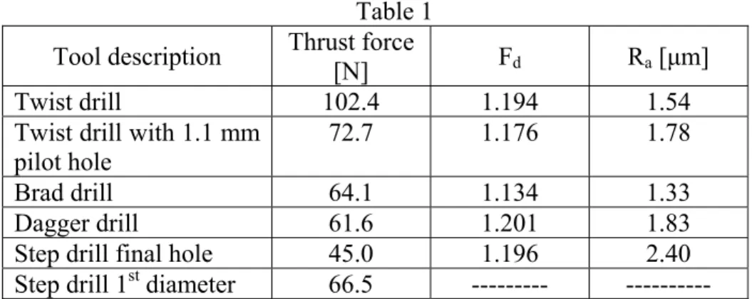
In order to establish a comparison between the several drill geometries used, the maximum thrust force was considered. These thrust force values are shown in table 1 and compared in fig. 8. In fig. 4 the thrust displacement curves for the drills used are presented, except for the commercial step drill. The influence of a pilot hole will be considered later.
The greater value was obtained when twist drill was used. For the other drills the maximum thrust is similar and slightly lower with step drill, although the curves are different. This demonstrates that the thrust forces and their development during plate drilling are dependent on drill geometry, among other factors, like feed and cutting speed. However, cutting parameters influence was not evaluated in the present work. Although the thrust force during drilling is also influenced by the material itself, the use of probes taken from the same plate allows us to present a ranking of the drills considering drilling thrust force. Different materials or stacking sequences shall lead to different thrust force values, but the relative distribution probably will not change. In order to assess the risk of delamination, the values resulting from the models presented in equations (1) and (2), and considering the last plies of the laminate as uncut thickness – 0.125 mm for 1 ply; 0.25 mm for 2 plies –, were compared with the thrust force at a corresponding drill displacement. An extra column considering ‘half-ply’ was created. The comparison is shown in table 3, with values where delamination is expected in bold.
Observing the values in this table, it is clear that the use of a twist drill without pilot hole has the greater probability of delamination occurrence. For the other tool geometries, the Brad drill has the lowest value for any displacement considered. This means that this geometry has the lowest risk of delamination occurrence, under the experimental conditions here described. The value for the Dagger drill was higher. This can be explained by the sharp geometry of the drill tip, reducing drill engagement for the tool displacement considered. So when the tip of the Dagger drill is reaching the uncut thickness considered for comparison the final cutting diameter is not engaged yet, causing the existence of two intervals where the thrust force remains approximately constant – one during tool engagement and the other after tool full diameter
engagement, the latter with lower value. For the step drill the value considered in this table was for the second diameter – 6mm. It is possible to observe that the use of a step drill clearly reduce the thrust force value when the last plies of the laminate are being cut. This reduction is an indication of the beneficial effect of the use of a step drill. However, the critical thrust force for delamination onset – Fcrit -shall be inferior as a result of the prior removal of material.
4.2 PILOT HOLE EFECT
The influence of the pilot hole is mainly related with the reduction of thrust force during drilling. However, it must be noted that the plate resistance to delamination is also reduced. So, the great reduction of thrust force that is achieved with the larger pilot hole used – 3.5mm – (table 2) has also a major risk of delamination. The balance between these two factors has to be achieved and related with non-destructive testing in order to decide what is the best solution for pilot hole diameter.
When comparing the holes with a twist drill, the value of the maximum force during final drilling is reduced by 30 to 75% depending on pilot hole diameter. This reduction is not influenced by the material used, being its nature merely mechanical. A similar effect can be observed when comparing thrust force values for the first diameter and final hole of the step drills in table 2. This can be explained by the division of the drilling effort in two stages, one for each drilling diameter. The first diameter reduces significantly the chisel edge effect, while the second diameter acts like a reamer, having no indentation effect and improving tool guidance. As it was already noted by Tsao and Hocheng (2003), the indentation effect is the main responsible for the thrust force and consequent extrusion mechanism that occurs during laminate drilling.
around the hole (table 3). Damage evaluation was obtained by enhanced radiography and only the best drilling strategy was selected for the C-scanning analysis. For every pilot hole diameter used, there was a reduction of the damage, independently of the criteria used. Even though there are no significant differences between the values of delamination factor or damage ratio for the various diameters considered, it is evident that the best results are always associated with the smaller pilot hole selected – 1.1 mm. In fact, the damage reduction for a 1.1 mm pilot hole is, on the average, 3%, followed by the intermediate diameter – 2.3 mm – with 2% of damage reduction. For the greater pilot hole considered – 3.5 mm – an opposite effect has resulted with an increase of damage criteria results when compared with a one step drill. The same adverse effect can be observed looking at the results of step drill. It must be noted that when pilot hole drilling strategy is used, the critical force for delamination onset is reduced. This reduction will be greater for larger pilot hole diameters.
4.3 USE OF NON-DESTRUCTIVE TECHNIQUES
As carbon/epoxy plates are opaque, visual inspection is not able to satisfactory assess the damage extension that can exist between inner plies of the laminate. So, it is fundamental to use other imaging methods when it is necessary to inspect drilled parts. The technique described in section 3 was applied for damage evaluation of the plates used in this work.
As illustrated in fig. 6, images obtained by radiography are suitable to be processed using appropriate Computational Vision techniques and to give information that allows the determination of delamination factor and damage ratio. Starting from the shape of a radiographic image, that is nearly circular, and using the processing steps described before (3.5), it is possible to have a number of results including:
- drilled area (dark grey in fig. 6f); - damaged area (light grey in fig. 6f);
- maximum damaged diameter (black frontier in fig. 6f).
The results of Delamination factor, equation (5) can be seen in table 2 and figure 8. For every criteria the best result, i.e., less delamination around the hole, was obtained with Brad drill. Results at this table show that the drill geometry has an influence on the delamination value. The peculiar geometry of Brad drill, pre-tensioning the fibre prior to cut, has enabled the achievement of delamination values around 1.1, for every criteria used. The delamination results of Dagger drill were better when considering the damage ratio than when considering the delamination factor. This can be the result of a less regular distribution of the damage around the hole for plates drilled with Dagger drill. In fact, for twist and Brad drills, the damage was more regularly distributed around the hole (fig. 5).
The use of a pilot hole has reduced the delamination, as already discussed. For the step drill, the effect was the opposite, with an increase of the damage observed in the results for every criteria used. The main reason for this result can be related with the geometry of the tool itself. The transition between the two diameters is not smooth, but sudden, as can be seen in fig. 3d, with an angle of 180º at the diameter step zone. The use of a smoother angle, in the range of 90 to 135º, at the transition could be helpful. Another reason can be related with the pilot diameter of the tool, equal to 3.4 mm. This diameter seems to be too high, as demonstrated in 4.2, consequently cancelling the beneficial effect of the pilot hole.
Results of hole surface roughness are presented in table 1 for tool comparison and in table 2 regarding pilot hole effect. About the latter, it is possible to say that no significant effect was found for the use of a two-step drilling strategy. In fact, the lower value of superficial roughness is associated with one-step drilling. The variation of the results considering average plus or minus standard variation has shown some overlapping in the gap of values for each pilot hole diameter measurement. No definitive influence was perceived.
The effect of each tool in surface roughness can be evaluated in table 1. As the feed rate was equal for all the tools, the values are able to give some indication about the individual effects of the cutting edge geometry in the final roughness value. The lower one was obtained with Brad drill and the larger with the step drill. If this tool is not considered the larger roughness measured was at the holes drilled with Dagger tool. Although some scattering was observed in the results, the roughness values for this drill are higher than the values obtained with the other drills with a helical flute.
However it should be noted that even though Ra is the most common mean of specification, is a poor indicator of surface damage, Ramulu (1998), so composites need a combination of several parameters to characterize the surface. The use of optical profilometers could be a complementary mean to achieve such goal.
5. CONCLUSIONS
Quasi-isotropic carbon/epoxy laminates were drilled with four different drill geometries, one of them with the additional use of a pilot hole. The results considered in this study were the maximum thrust forces during drilling, measurement of delamination by delamination factor, Fd and characterization of surface roughness. In order to apply the mentioned delamination criteria, the damage around the hole was evaluated by the use
of enhanced radiography and the resulting images were analysed by a computational vision technique in order to provide the areas and diameters of the damaged region around the drilled hole.
From the results presented, it is possible to draw some conclusions:
The drill geometry has an influence on the results used for evaluation: maximum thrust force and delamination around the hole.
Considering the damage around the hole, the Brad drill seems to be the most appropriate tool for composite laminates drilling.
The use of a pilot hole has some beneficial effects, like thrust force reduction, thus less risk of delamination, and reduced damage around the hole. The influence of the pilot hole diameter was also evaluated. The use of a 1.1 mm pilot hole – 18% of final diameter – gave the best results.
Some correlation between thrust force values and delamination was found. However, due to a different cutting mechanism, which starts the cut right after contact avoiding indentation effect, the result for Dagger drill should not be included in such correlation. Drilling in steps should also be excluded.
The step drill was a good starting point for the development of an alternative tool for composite laminates, being able to perform the pilot and final hole in one single step.
The use of Computational Vision techniques was useful in the determination of the damage caused by drilling. The processing and analysis sequence can be used for the measurement of damage in other materials.
The significance of surface roughness for damage assessment seems to be limited by the use of only one parameter. Combination of parameters should be preferable.
The first author wishes to thanks to “Programa de Desenvolvimento Educativo para Portugal (PRODEP) III” for supporting the work here presented.
REFERENCES
Abrate, S., (1997) “Machining of Composite Materials”, Composites Engineering Handbook, P. K. Mallick, Marcel Dekker, New York, 777-809;
Awcock, G. W., Thomas, R., (1995) “Applied image processing”, McGRAW-HILL International Editions, New York;
Bader, M. G., (1994) “Hybrid effect”, Handbook of Polymer-fibre Composites, Longman Scientific Technical, 225-230;
Chen, W. C., (1997) “Some experimental investigations in the drilling of carbon fibre-reinforced plastic (CFRP) composite laminates”, Int. J. Machine Tools and
Manufacture, 37, 1097-1108;
Eriksen, E., (1999) “Influence from production parameters on the surface roughness of a machined short fibre reinforced thermoplastic”, Int. J. Machine Tools and
Manufacture, 39, 1611-1618;
Evans, N., (1996) “The applicability of radiography to the inspection of composites”, Non-destructive testing of composite materials, Imperial College, London, 5/1-5/8; Hamdoun, Z., Guillaumat, L., Lataillade, J. L., (2004) “Influence of the drilling on the fatigue behaviour of carbon epoxy laminates”, ECCM 11, Rhodes, Greece;
Hocheng, H., Dharan, C. K. H., (1995) “Delamination during drilling in composite laminates” J. of Engineering for Industry, 112, 236-239;
Hocheng, H., Puw, H. Y., (1992) “On drilling characteristics of fibre-reinforced thermosets and thermoplastics”, Int. J. Machine Tools and Manufacture, 32, 583-592;
Hocheng, H., Tsao, C.C., (2003) “Comprehensive analysis of delamination in drilling of composite materials with various drill bits”, J. Mat. Proc. Techn., 140, 335-339;
Jain, R., Kasturi, R., Schunck, B. G., (1995) ”Machine Vision”, McGRAW-HILL International Editions, New York;
Jung, J. P., Kim, G. W., Lee, K. Y., (2005) “Critical thrust force at delamination propagation during drilling of angle-ply laminates”, Composite Structures, 68, 391-397;
Lachaud, F., Piquet, R., Collombet, F., Surcin, L., (2001) “Drilling of composite structures”, Composite Structures, 52, 511-516;
Mehta, M., Reinhart, T. J., Soni, A. H., (1992) “Effect of fastener hole drilling anomalies on structural integrity of PMR-15/Gr composite laminates”, Proc. of the Machining Composite Materials Symp., ASM Materials Week, 113-126;
Persson, E., Eriksson, I., Zackrisson, L., (1997) “Effects of hole machining defects on strength and fatigue life of composite laminates”, Composites A, 28, 141-151;
Persson, E., Eriksson, I., Hammersberg, P., (1997) “Propagation of hole machining defects in pin-loaded composite laminates”, J. of Composite Materials, 31, 4, 383-408; Piquet, R., Ferret, B., Lachaud, F., Swider, P., (2000) “Experimental analysis of drilling damage in thin carbon/epoxy plate using special drills”, Composites A, 31, 1107-1115; Ramulu, M., (1998) “Characterization of Surface Quality in Machining of Composites”, Machining of Ceramics and Composites, Ed. Marcel Dekker, 575-648;
Schalkoff, R. J., (1989) “Digital image processing and computer vision”, John Willey & Sons, Inc.;
Stone, R., Krishnamurthy, K., (1996) “A Neural Network Thrust Force Controller to Minimize Delamination During Drilling of Graphite-Epoxy Composites”, Int. J. Machine Tools and Manufacture, 36, 985-1003;
Tavares, J. M. R. S., (2000) Ph. D. Thesis: “Análise de Movimento de Corpos Deformáveis usando Visão Computacional”, FEUP, Porto;
Tavares, J. M. R. S., Barbosa, J. G., Padilha, A. J., (2002) “Apresentação de um Banco de Desenvolvimento e Ensaio para Objectos Deformáveis”, RESI – Revista Electrónica de Sistemas de Informação, vol. 1;
Tsao, C.C., Hocheng, H., (2003) “The effect of chisel length and associated pilot hole on delamination when drilling composite materials”, Int. J. Machine Tools and Manufacture, 43, 1087-1092;
Tsao, C.C., Hocheng, H., (2004) “Taguchi analysis of delamination associated with various drill bits in drilling of composite material”, Int. J. Machine Tools and Manufacture, 44, 1085-1090;
Tsao, C.C., Hocheng, H., (2005) “Computerized tomography and C-Scan for measuring delamination in the drilling of composite materials using various drills”, Int. J. Machine Tools and Manufacture, 45, 1282-1287;
Won, M. S., Dharan, C. H. K., (2002) “Drilling of aramid and carbon fibre polymer composites”, Trans. of ASME J. of Manuf. Science and Engineering, 124, 778-783;
CAPTIONS Figure 1 – Peel-up delamination at entrance. Figure 2 – Push-out delamination at exit.
Figure 3 – a) twist drill; b) Brad drill; c) Dagger drill; d) step drill. Figure 4 – Thrust force versus displacement curves.
Figure 5 – Radiographies of drilled parts: a) twist drill; b) Brad drill; c) Dagger drill. Figure 6 – Example of the determination of the necessary measurements in an image obtained by radiography using Computational Vision techniques.
Figure 7 – Comparison of maximum thrust forces during drilling. Figure 8 – a) Delamination factor (Fd) results with radiography images.
Table 1 – Maximum thrust force, delamination factor (Fd) and Ra results. Table 2 – Pilot hole effect.
FIGURES Figure 1 Figure 2 a) b) c) d) Figure 3
0 20 40 60 80 100 120 0 1 2 3 4 5 6 7 8 9 10 11 12 13 14 15 Displacement [mm] T h ru st f o rc e [ N ] twist c-shape dagger Figure 4 a) b) c) Figure 5
a) Original image (25% reduced).
b) Interest zone (100%). c) After smoothing.
d) After segmentation. e) After morphological filters applied.
f) Area identification and measurement results. Figure 6
0 20 40 60 80 100 120
twist brad dagger step
Drill Th ru st fo rc e [ N ] Figure 7 1 1,05 1,1 1,15 1,2 1,25
twist brad dagger step
Drill D el am in ati on fa cto r [F d] Figure 8
TABLES
Table 1 Tool description Thrust force
[N] Fd Ra [μm]
Twist drill 102.4 1.194 1.54
Twist drill with 1.1 mm
pilot hole 72.7 1.176 1.78
Brad drill 64.1 1.134 1.33
Dagger drill 61.6 1.201 1.83
Step drill final hole 45.0 1.196 2.40
Step drill 1st diameter 66.5 --- ---
Table 2 Tool description Thrust force
[N] Fd Ra [μm]
Twist drill 102.4 1.194 1.54
Twist drill with 1.1 mm
pilot hole 72.7 1.176 1.78
Twist drill with 2.3 mm pilot hole
49.3 1.186 1.66 Twist drill with 3.5 mm
pilot hole
24 1.199 1.61
Table 3
Tool / Model Thrust force for n uncut plies ( 1ply = 0.125mm) [N] n = 1/2 n = 1 n = 2
Twist drill 79.7 84.2 91.6
Twist drill with 1.1
mm pilot hole 45.5 50.5
56.2
Brad drill 43.2 45.1 47.8
Dagger drill 56.9 57.6 59.2
Step drill 4.3 8.6 20.3
Fcrit acc. eq. (1) 14 40 113