“Simplicity is the ultimate sophistication” — Leonardo Da Vinci
Universidade de Aveiro Departamento deElectr´onica, Telecomunica¸c˜oes e Inform´atica, 2010
Patrick Ferreira
Marques
Arquitectura concorrente para o controlo de um
ve´ıculo aut´
onomo
Concurrent architecture for control of an
autonomous driving vehicle
Universidade de Aveiro Departamento deElectr´onica, Telecomunica¸c˜oes e Inform´atica, 2010
Patrick Ferreira
Marques
Arquitectura concorrente para o controlo de um
ve´ıculo aut´
onomo
Concurrent architecture for control of an
autonomous driving vehicle
Disserta¸c˜ao apresentada `a Universidade de Aveiro para cumprimento dos requisitos necess´arios `a obten¸c˜ao do grau de Mestre em Engenharia de Computadores de Telem´atica, realizada sob a orienta¸c˜ao cient´ıfica do Prof. Dr. Artur Jos´e Carneiro Pereira e do Prof. Dr. Jos´e Lu´ıs Costa Pinto de Azevedo, professores do Departamento de Electr´onica, Telecomunica¸c˜oes e Inform´atica da Universidade de Aveiro.
o j´uri / the jury
presidente / president Doutor Ant´onio Rui de Oliveira e Silva Borges Professor Associado da Universidade de Aveiro
vogais / examiners committee Doutor Paulo Jos´e Cerqueira Gomes da Costa
Professor Auxiliar da Faculdade de Engenharia da Universidade do Porto
Doutor Artur Jos´e Carneiro Pereira
Professor Auxiliar da Universidade de Aveiro (orientador)
Doutor Jos´e Lu´ıs Costa Pinto de Azevedo
agradecimentos Gostava de deixar aqui os meus agradecimentos a todas as pessoas que de alguma forma participaram e/ou influenciaram a realiza¸c˜ao deste projecto. Come¸cando pelos meus pais e tios, que sempre me deram for¸cas para terminar este trabalho. Obrigado a todos os professores que me deram forma¸c˜ao, especialmente aos meus orientadores pela motiva¸c˜ao dada e ajuda prestada ao longo do ´ultimo ano bem como todo o conhecimento transmitido. Tamb´em agrade¸co aos meus amigos que sempre ajudaram e apoiaram nos momentos mais dif´ıceis.
Palavras-chave Rob´otica, Arquitectura Concorrente, Rob´otica Aut´onoma e M´ovel, Condu¸c˜ao Aut´onoma, Festival Nacional de Rob´otica
Resumo Os robˆos aut´onomos e os ve´ıculos n˜ao tripulados s˜ao vertentes da rob´otica de forte investiga¸c˜ao durante os ´ultimos anos, especialmente para o de-senvolvimento de ve´ıculos aut´onomos destinados `a explora¸c˜ao de lugares in´ospitos. Um robˆo aut´onomo ´e uma m´aquina que consegue ser indepen-dente e regida pelas suas pr´oprias leis, um sistema que consegue sobreviver num ambiente natural sem interven¸c˜ao humana. Hoje em dia s˜ao muitos os sistemas dispon´ıveis (como por exemplo GPS e vis˜ao computorizada) que ajudam os robˆos a sobreviver, sendo o grande desafio integr´a-los de forma a produzir um ser mais inteligente, s´olido e confi´avel.
O Departamento de Electr´onica, Telecomunica¸c˜oes e Inform´atica da Uni-versidade de Aveiro tem realizado, nos ´ultimos anos, trabalho na ´area da condu¸c˜ao aut´onoma. Um dos objectivos desse trabalho tem sido o desen-volvimento de ve´ıculos aut´onomos para participa¸c˜ao na prova de condu¸c˜ao aut´onoma do Festival Nacional de Rob´otica, na qual participa desde 2001. O software de controlo de alto n´ıvel do ve´ıculo actual assentava numa estru-tura sequencial o que torna complexa a tarefa de manuten¸c˜ao e integra¸c˜ao de novas funcionalidades. Actualmente existem m´odulos para a descri¸c˜ao do mundo bem como para o planeamento de traject´orias sobre esses modelos e um m´odulo para percep¸c˜ao a partir de imagem.
O objectivo deste trabalho foi o de reestruturar todo o software de alto n´ıvel, tornando-o modular e concorrente permitindo dessa forma uma mel-hor manuten¸c˜ao, actualiza¸c˜ao e evolu¸c˜ao. Fica assim mais f´acil a substi-tui¸c˜ao de m´odulos, a incorpora¸c˜ao de novas funcionalidades e o trabalho de equipa. A nova estrutura assenta na existˆencia de uma mem´oria central e partilhada, tipo blackboard, onde os v´arios m´odulos recolhem os dados de que necessitam e depositam os dados produzidos.
Este novo modelo arquitectural foi implementado no ve´ıculo e testado du-rante a edi¸c˜ao de 2010 do Festival Nacional de Rob´otica, tendo alcan¸cado o terceiro lugar. A arquitectura apresentada incorporou v´arios sistemas j´a ex-istentes, tendo como principais vantagens a modularidade e extensibilidade dentro de um ambiente concorrente e com informa¸c˜ao distribu´ıda.
Keywords Robotics, Concurrent Architecture, Autonomous Robots, Autonomous Driving, Portuguese Robotics Open
Abstract The autonomous robots and unmanned vehicles have been an intensive field of research in the last years for driverless cars and harsh environments exploration. An autonomous robot is a machine that can work in an inde-pendent way and subject to its own laws only, a system that can survive in the real-world environment without human intervention. Today many systems are available (e.g. GPS, Computer Vision) that aid the robots to survive, being the biggest challenge put all together and create an agent more intelligent, robust and reliable.
The Department of Electronics, Telecommunications and Informatics of Uni-versity of Aveiro in the last years has worked in the autonomous driving area. One point of this work has been the developing of autonomous ve-hicles for participation in the autonomous driving inside competition of the Portuguese Robotics Open, where it has participated since 2001.
The high level software that controls the actual vehicle is based on a se-quential structure that turns maintenance and integration of new modules in a complex task. Currently, there are modules to carry out several basic tasks, namely, image perception and integration, “world” representation, and creation of trajectory plans
The aim of this work is the reorganization of the existent high-level soft-ware, following a modular and concurrent paradigm. The new software organization makes it easier to replace software modules and to add new functionalities, enhancing team work development and maintenance. The new structure is based on the existence of a central shared memory, like a blackboard, where the modules collect data that they need as well as publish produced data.
This new architectural approach has been implemented in the ROTA robot and it was tested in the 2010 Portuguese Robotics Open (where it ranked 3rd). The proposed architecture links several existing systems and has as strongest points modularity and extensibility in concurrent environment with distributed information.
Contents
Contents i
List of Figures iii
List of Tables v
1 Introduction 1
1.1 Autonomous Robots and Autonomous Driving . . . 1
1.2 Portuguese Robotics Open. . . 2
1.2.1 Junior Class. . . 2
1.2.2 Senior Class. . . 2
1.3 The Rota Platforms . . . 4
1.4 Motivation . . . 7
1.5 Goals . . . 8
1.6 Thesis outline . . . 10
2 Robot Architectures 11 2.1 Robot architecture . . . 11
2.2 Robot Control Paradigm. . . 12
2.2.1 Reactive paradigm, Don’t think, (Re)Act . . . 12
2.2.2 Deliberative paradigm, Think, them Act . . . 12
2.2.3 Hybrid paradigm, Think and Act concurrently . . . 13
2.2.4 Behavior-Based paradigm, Think the way you Act . . . 14
2.3 System architectures . . . 16
2.3.1 SPA (Sense Plan Act) . . . 16
2.3.2 Subsumption . . . 17
2.3.3 SSS . . . 18
2.3.4 ATLANTIS . . . 19
2.3.5 AuRA . . . 19
2.3.6 Three Tiered Architecture . . . 21
2.3.7 Triple-Tower Architecture . . . 22
2.4 Conclusion . . . 25
3 ROTA Architecture 27 3.1 Architecture module . . . 28
3.2 Rota Data Base . . . 29
3.4 Track Representation. . . 31
3.5 Perception . . . 34
3.6 Low-level communication handler . . . 35
3.7 Decision and Action . . . 36
3.8 Process Synchronization . . . 38
4 Vision system 41 4.1 Vision System Architecture . . . 41
4.2 Images Database . . . 42
4.3 Capture Process . . . 44
4.4 Visualization and recording . . . 46
4.5 Road Image Processing . . . 47
4.5.1 Points of interest extraction . . . 47
4.5.2 Road Analysis . . . 50
4.6 Traffic Sign Detection . . . 51
5 Results 55 5.1 Scanlines . . . 55
5.2 Vision System. . . 55
5.3 Template matching . . . 56
5.4 Portuguese Robotics Open. . . 59
6 Conclusions 61 6.1 Work Summary . . . 61 6.2 Conclusions . . . 62 6.3 Future Directions . . . 62 Bibliography 65 Appendices 69 A Configuration Files 69 A.1 RTDB Configuration . . . 71
A.2 World Map . . . 72
A.3 Process Manager . . . 73
A.4 Images Database Configurations . . . 74
A.5 Camera Configurations . . . 75
List of Figures
1.1 Competition elements . . . 3
1.2 ROTA Project cars platfrorms . . . 5
1.3 Global Architecture . . . 5
1.4 Architecture of the base on each car . . . 6
1.5 New positions for the cameras . . . 6
1.6 State Machine of the old ROTA software. . . 8
2.1 Reactive Paradigm . . . 12
2.2 Deliberative Paradigm . . . 13
2.3 Hybrid Paradigm . . . 14
2.4 Behavior Based . . . 15
2.5 Shakey Robot . . . 16
2.6 SPA, traditional Artificial Intelligence robot brains are serial processing units. 17 2.7 Subsumption layers. . . 17
2.8 TalrikTMJr. AVR SSS testing . . . 18
2.9 Servo, subsumption, and symbolic (SSS) by Jonathan H. Connell . . . 18
2.10 ATLANTIS Architecture. . . 20
2.11 Autonomous Robot Architecture . . . 21
2.12 Three-Tier (3T) Architecture . . . 21
2.13 Triple-Tower Architecture . . . 22
2.14 Real-Time Control System Paradigms . . . 23
2.15 Space and Time resolution in each layer . . . 24
2.16 Reactive vs Deliberative . . . 25
3.1 ROTA architecture components . . . 28
3.2 Generic descriptor of entities . . . 28
3.3 RtDB, a distributed database . . . 30
3.4 Pit Box and RtDB . . . 31
3.5 Examples of support sections in this structure . . . 32
3.6 Portuguese Robotics Open track sections and borders . . . 33
3.7 Portuguese Robotics Open track sections and borders . . . 33
3.8 Coordinates Systems . . . 34
3.9 Car Coordination System . . . 34
3.10 Low-Level communications . . . 35
3.11 Example of State Machine for 3rd round . . . 36
3.13 PMAN Factory class diagram . . . 39
3.14 Rota actual Software cycle / sequence . . . 39
4.1 Shared Image architecture . . . 42
4.2 Shared Image Implementation . . . 43
4.3 Capture Class Diagram . . . 44
4.4 Capture work flow . . . 45
4.5 Matrix of color conversions . . . 46
4.6 Viewer, a simple GUI application to show images . . . 46
4.7 Recorder Class Diagram . . . 47
4.8 ROIs, real coordinates vs the pixel coordinates . . . 48
4.9 Image sensors . . . 49
4.10 Road Vision work flow . . . 49
4.11 Road Analyzes . . . 50
4.12 Signs Vision (Template Matching) work flow . . . 51
4.13 Template match example . . . 53
List of Tables
1.1 ROTA versus RatoZinger hardware specifications . . . 7
5.1 Templates dimensions . . . 57
5.2 Average time for template matching processing . . . 57
Chapter 1
Introduction
1.1
Autonomous Robots and Autonomous Driving
Robots are synthetic or/and mechanical creatures “that perform tasks by manipulating the physical world”[1]. With embedded computational intelligence, they are “systems with capabilities far exceeding the core components alone”[2, 3]. There is other definition in lit-erature sometimes more embracing, “Robotics is the intelligent connection of perception to action (..) the intelligent connection of perception to action replaces sensing by perception and software by intelligent software”[4] or “a robot is a multi-disciplinary engineering device”[5]. Few years ago Robotics Industry Association (RIA) defined a robot as a “re-programmable, multifunctional, manipulator designed to move material, parts, tools, or specialized devices through variable programmed motions for the performance of a variety of tasks” (Jablonski and Posey 1985), a concept that is almost for “assembly robots”, workers that operates in factories.
Nowadays these “beings”, created to work inside buildings, start to go everywhere and perform the most varied tasks in wide areas, some of them unachievable by humans. They bring new challenges and requirements specially to work in the real-world (human-centered and life-like robotics) with the less human intervention as possible, introducing autonomy and intelligence[6,7].
An autonomous robot is a machine that can work in an independent way and subject to its own laws only, a system that can survive in the real-world environment. Thus a robot must have sensors and processing ability that emulates some aspects of cognition and actuators [8, 9]. The sensors retain information about surrounding world, commonly uses computer vision supported by cameras or/and laser range finders, but every sensor that catch important data is an asset. All this data is processed to generate an output that normally gives a motion to some robot element(s).
Some robots have locomotion capabilities, based on caterpillars, wheels, legs, among oth-ers, thus enabling the ability to move from one place to another in the environment.[10,3,1] The autonomous driving consists in bringing autonomy to mobile robots, providing not only ability to perform actions in the environment but also for robot displacement.
Hence, due to the wide robotics area we can define it as “a mechanism which is able to move and react to its environment”[6].
1.2
Portuguese Robotics Open
In 2001 took place the first edition of the Portuguese Robotics Open, a yearly event, which aims promotion of science and technology through robotic competitions. Initially organized by five universities, University of Aveiro, University of Minho, University of Porto, University of Coimbra and Technical University of Lisbon, is now on the responsibility of the Portuguese Robotics Society. This event has an international scientific meeting and various competitions divided in junior and senior classes.
1.2.1 Junior Class
The junior league includes three leagues, search and rescue, dance and small size soccer. Search and Rescue
“The competition of Search and Rescue Junior is closely related with the RoboCup Junior Rescue (Rescue RCJ). In this competition mobile robots are used to quickly and accurately identify victims in disaster scenarios that are recreated artificially. These scenarios will range in complexity from line-following on a flat surface through paths with obstacles, line breaks and slopes, to reach an area where the victims are randomly placed in open terrain”.[11,12,13] Dance
“The dance competition follows theRoboCupofficial rules and consists in the realization of a choreography in which one or more robots “dance” to the rhythm of music, being evaluated by a panel of experts in Robotics and Dance. From the point of view of programming, this competition is very little demanding. Nevertheless, the final result, which is the combination of the movement of the robots with the music along with the imagination that is put on some choreographies, achieves good levels of artistic beauty”. [11,12,13]
Soccer
“This competition is based on a two by two fully autonomous robots, filled with sensors and who’s limit dimensions are 22cm, playing soccer. An infrared emitting ball and two different sized soccer fields, with different complexity in the programming level, are the remaining subjects for this exciting competition filled with soccer strategies and goals. The soil of the fields is green and the goals are colored blue and yellow so that robots may indentify them. On the simplest field version there are no sidelines or goal lines and it’s allowed to play with the protection walls. The second filed version has sidelines and goal lines and ball is not allowed to leave from inside those lines”. [11,12,13]
1.2.2 Senior Class
The senior competition includes middle size soccer and autonomous driving. Middle Size Soccer
“The Middle Size League (MSL) is an officialRoboCupleague. Middle-sized robots, of no more than 50 cm diameter, play soccer in teams of up to 5 robots on a field the size of 12x18
metres. Matches are divided in 15-minute halves. All sensors are on-board. Robots can use wireless networking to communicate. Two teams with (typically) 5 robots than can have up to 80 cm height, 50 cm in diameter and 40 Kg of weight, challenge each other in a football field . This field is similar to the human one which has 11 players, but with a smaller size (18m x 12m)”. [11,12,13]
Autonomous driving competition
The Autonomous driving competition is directly related to the work of this thesis and so, is described in more detail. In this competition a road track is recreated. The track is 8 shaped with two lanes and a fixed crosswalk, above which a traffic light panel is placed, as depicted in figure 1.1a. The road is a black carpet delimited by two continuous white lines and a central one that is dashed. The crosswalk and both lines are made of white tape. The Light signs are: STOP (red), FRONT (green), CHESS (red and green chess) and RIGHT and LEFT (both yellow) as shown in the figure1.1b. Also, there are dynamic elements, i.e., scenario objects that change their positions along the competition: two obstacles (covered of green carpet), which occupy almost one lane; a tunnel, where the entry and exit vertical edges and its interior walls are white colored; a roadworking area, delimited by maintenance cones, which creates a detour from the original route of the track. The cones are orange and white color (similar to the real ones) and each pair of consecutive cones is connected by red and white tape
There are also 6 traffic signs placed outside the track, along it. The exact positioning of those signs is unknown in advance, and the robot is awarded with additional points whenever it detects and correctly identifies a sign. The set of signs used in competition includes: two warning signs (triangular shape), two mandatory signs (round shape), and the other two are information or services signs (square shape) as depicted in the figure1.1c. One of this traffic signs identifies a reserved lane that is also defined by a central continuous line as shows on left of figure1.1a.
(a) The competition track (b) Traffic lights (c) Traffic signs Figure 1.1: Competition elements [14,15]
The event is divided in 3 stages, during 3 days (each one per day) along which difficult increases.
The first stage is a speed race with two laps on the track. No elements are placed on the track and the traffic lights are only used to start and end the race. The car is placed at the beginning of the zebra cross and starts running when traffic light change from stop sign to the “follow along” one. During the first three half laps the car can follow any direction (ignoring traffic lights indications) and on the last lap (fourth half lap) traffic lights have the stop sign and the car has to stop.
The second stage has some additional difficulties. Every time the car approaches the zebra cross it has to obey the displayed traffic light signal: stop, go straight, turn left, and turn right. The track now contains an obstacle, whose location is unknown in advance, and the car has to avoid it. In the end of 2 laps and after a light panel indication the car must perform a parking maneuver, choosing one of the two places available.
The third stage has another two challenges, the working area and the tunnel. The tunnel introduces a luminosity problem because there is no light inside it. In the working area the car has to drive using the maintenance cones. In the end of this last stage the car has also to perform a parking maneuver. Since one of the two places is occupied by an obstacle, the robot has to identify the free place and park in it.
This environment is indoors and with restrictions in colors and shapes, i.e. a controlled-environment that simplifies some hard problems of the real-world, like the sun and road wear. More details can be found in the Rules and Technical Specifications of the competition [14].
1.3
The Rota Platforms
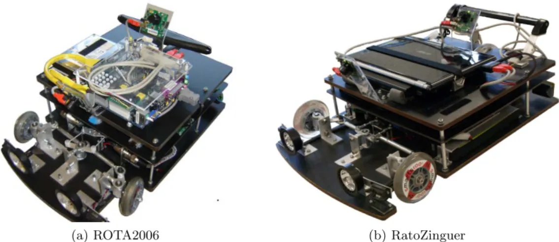
As stated before, DETI/IEETA participates in the Autonomous Driving Competition since the very beginning, in 2001. In 2006, the competition organizers decided to change the track configuration to the one described in the previous section. By that time, DETI/IEETA also decided to build a new vehicle platform. It was called ROTA (RObˆo Triciclo de Aveiro – Tricycle Robot from Aveiro) figure 1.2aand was developed in the context of a master thesis work [16].
Two years later, in 2008, a new version of the vehicle was developed. It was called RatoZinguer figure1.2band the main motivation for its construction was the need to overcome some drawbacks of the previous one. Since the global structure of both platforms is very similar, the next sections only depict the main differences between them.
Mechanical layer
Both robots have the same mechanical layer, 3 wheels (tricycle), one for traction and the other two for the Ackermann steering1. The energy is supplied by two batteries, one giving power to the logic layer and another to the traction motor (in the first version batteries also provides energy to motherboard). Cutting off the power to the traction motor puts the rear wheel in free moving, which is quite helpful during development, since the vehicle can be pushed by hand while all the other functionalities can be analyzed.
(a) ROTA2006 (b) RatoZinguer Figure 1.2: ROTA Project cars platfrorms
Figure 1.3: Global Architecture
Because the carpet sometimes has imperfections and the car also has a low profile, the ride height was increased in the second version of the platform. This prevents the car stuck or carpet break. The new platform has also new batteries, smaller and light.
Low level layer
The low level layer is composed of a set of nodes that communicates by a through a CAN (Controller Area Network) bus. All the orders for actuators and data from sensors are transmitted to the PC by a gateway with Universal Serial Bus (USB) connection using the network like depicted in figure1.4.
Vision subsystem
The cars have a camera in the front and other in the rear, being the first used to percept the road and the latter used to detect and identify the traffic signs. In the first platform (ROTA), the front camera is very near to the floor, having an angle closest to 0o to the road, which makes it more susceptible to light interferences and distance distortions. This year the
Figure 1.4: Architecture of the base on each car. [15]
new signs are placed at the curb on the track right side and, consequently also on the right side of the car, outside of the field of view of both cameras.
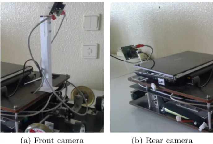
(a) Front camera (b) Rear camera
Figure 1.5: New positions for the cameras, the original is depicted in figure1.2b
To solve these two issues the mounting positions of both cameras has been changed (see figure1.5a). The “road camera” is now mounted in a higher position and thus the angle with the road has also increased, which reduces image distortion and potentially the environment light interference. The rear camera has to be placed on the right side of the car to catch the new vertical signs as the figure1.5bshows. The opening of the rear camera lens was increased in order to have adequate field of view for both the signs, the traffic lights and the new ones along the right side of the track.
High level control
The ROTA vehicle has on top a motherboard for high level processing but this requires an external monitor, keyboard and mouse, which proved to be quite cumbersome in a competition
environment. This gives enough computation power but also consumes energy from the main batteries reducing the overall autonomy.
To avoid this constraint the new platform (RatoZinguer) was designed in order to use a laptop that provides all the hardware to work as well as its own battery. There is also some difference in the computation power as can be seen in the table1.1
ROTA RatoZinguer
Processor 1GHz Core 2 Duo 2.2Ghz
RAM 256Mb 2Gb
Table 1.1: ROTA versus RatoZinger hardware specifications
1.4
Motivation
The autonomous driving is a great challenge that involves different areas, such as computer vision, data fusion, artificial intelligence, usually in form of behaviors, skills or schemas, and robot control. A common challenge is the need to achieve the best performance always with real-time implications, which makes the best solutions to some problems of not easy (or even impossible) implementation. This area of robotics takes big part in new discoveries, like space and seabed exploration, nuclear works, medicine robots, rescue activities, et al. We need such technology to explore places where the humans nowadays cannot reach, and to do tasks that put their lives in danger or for which they do not have the required precision. Bekey [2] gives the example of the space travel. Going to mars takes more than 1 year and another to back and the planet don’t have means to support human life which makes the travel impossible at present (or even in the next years). However, robots can do the job for us. Also the humans naturally make mistakes and in such journey or/and task it cannot happen at all. Avoiding failures is another big challenge.
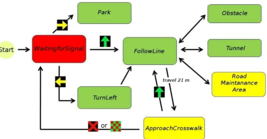
The control software of an autonomous driving vehicle is a complex structure, composed of several modules, in order to cover the different areas referred above. To deal with such complexity the choice of the software architecture plays a central role. This software archi-tecture can make easy or difficult to insert new modules, to change the existing ones, or to find and fix problems. In the ROTA project the software designed in the last years is now be-coming complex to maintain and evolve, and the actual architecture starts to be deprecated. The software of the robot consists of a single main program and several individual modules. Figure1.6represents a state machine for complete the last stage of the Portuguese Robotics Open competition, where each one of this state contains a sequence of actions. For example: grab image, process image, get data from sensors, process command to actuators and send command to the actuators. It is a difficult task the implementation of new behaviors and the updating of the current ones. Thus, a new software architecture is required.
Other point which already has been thought for some time ago is the creation of a pit box and also a remote control that gives a better support in developing environment but in competition too.
Figure 1.6: State Machine of the old ROTA software, this is where every part of the software is combined to create the agent intelli-gence. [15]
1.5
Goals
As stated in the previous section, the existing software architecture at the beginning of this work started to be deprecated. The project was started with a monolithic software approach, an unique application responsible not just for a particular task, but can perform every step needed to complete the goals. The project has few years and a faster growing took place in the last two, where new modules were created but the main structure of the software (its architecture) do not suffered any relevant change. Even, there were developed modules, like the path planning one, that were not used due to difficulties in incorporating them in the existing software. Thus, the main goal of this work was to design and implement a new software architecture that overcomes the drawbacks of the existing one.
It was a requirement that the new architecture should be adapted from the one used in theCooperative Autonomous Mobile roBots with Advanced Distributed Architecture (CAM-BADA) project. A good reason supported this decision. The CAMBADA project belongs to the same research group, Actividade Transversal em Rob´otica Inteligente (ATRI), and is responsible for the development of a team of robotic soccer players. The software architecture used in the robots proved to be a good solution and seemed to be adaptable to the ROTA vehicle. This also allows the sharing of code between projects, which potentiate the saving of development time.
The new architecture unfolds around a central data store, containing information items. Different processes play different roles, producing or consuming items. Part of the data store can be shared between different computer nodes. This allows for the communication between vehicles and between a vehicle and a Pit Box.
The new architecture should incorporate as much as possible all the existing modules. For that, these modules may need some adjustments, in which cases they have to be done during this work.
Other constraint on the work flow is the deadline for autonomous driving competition which took place in Leiria between 24 and 28 of March. The majority of the test in the project are performed in the lab that almost all the time has the same scenario. This event
gives an opportunity to test the robot in a track where surrounding environment is unknown and all the elements can be tested together. Thus the architecture should be well defined by that time and implemented so that the event can be used as a case of study.
The software architecture should be very solid and so simple. Some design specifications and requirements are describe in the list bellow.
Reactivity to the environment
The robot should be react to sudden changes in the environment, and thus it needs to promptly respond to world events most of the times in very narrow time windows. Intelligent behavior
The robot behavior in response to environment events should be made based on com-mon sense rules to exhibit intelligent behavior. Reaction to stimuli must be aware of objectives of its main goal.
Multiple sensor integration
The platform has several sensors with limited accuracy and reliability. The software should process and fuse data produced by different sensors in order to take decisions based on a more reliable source of information.
Resolving of multiple goals
With multiple goals some situations may cause conflicts in concurrent actions or behav-iors. The control system should provide means to deal with those multiple goals. Robustness
Uncertainties of measurements produce unexpected events and may produce wrong driving behaviors. The robot must handle imperfect inputs and sudden malfunctions. Reliability
The robot should recover from failure continuing, if possible, to work (only if it’s not a crucial error that gives malfunctions). Even when a critical error occurs, it should be possible to restart the system and try to continue the normal operation.
Programmability
The project is focused on the competition in the Portuguese Robotics Open but the robot should be easily re-programmed to execute different goals, instead of only one precise task.
Modularity
All the robot software should be divided in smaller subsystems, also called modules, that helps to incrementally add new features and update existent ones. The maintenance is improved as well as the debugging.
Flexibility
The robot is developed taking the autonomous driving competition rules and specifi-cations. However, the research is a key point of the project, and hence the software structure has to be very flexible in order to support continuous changes required by different research experiments.
Expandability
The main aim of the project is the research in autonomous driving area. Hence, the architecture should be easily expansible to build, integrate (incrementally) and test new systems.
Adaptability
The control software as all the architecture must encompasses world changes. These events could be very fast and unpredictable but the system should be adaptable in order to act smoothly but rapidly.
Global reasoning
High level software reasoning should have consciousness of the overall situation and take into account errors from sensing misinterpretation of the sensory data and to fuse the partial available information.
Asynchronously
The hardware car platform is mainly composed of two systems, the CAN network and the Laptop that has asynchronous communication. The architecture should support asynchronous communication and hide it the most possible to programmers.
1.6
Thesis outline
The remaining document is structured in the next chapters:
Chapter 2 gives an overview of available robot architectures in the literature. It presents the paradigms for robot control and the research in the robot architectures from the last years as well as some weakness and strengths of each one.
Chapter 3 presents the proposed software architecture for the high level subsystem. It gives an overview of the concurrent architecture and of the modules that are used on it. This chapter also briefly describes the communication between high and low-level and a pitbox approach for the vehicle as part of a distributed system.
Chapter 4 presents all the details of the modules that belong to the Vision System. The actual platform has two cameras and this is the main source of information to feed the data models. The vision system software is divided in 3 elements, image capture, preprocessing and analysis.
Chapter 5 presents results of the proposed architecture. This depicts some tests and results performed to the implemented modules.
Chapter 2
Robot Architectures
Even assuming there was a requirement to adapt the CAMBADA software architecture, it was decided to consult the literature in order to analyze which architecture styles are usually used, evaluating their weaknesses and strengths.
This chapter describes the survey done giving a overview of available robot architectures in the literature, and presenting the paradigms for robot control. The former represents how the robot software may be structured while the latter shows different approaches to create a robot control system.
2.1
Robot architecture
“An architecture describes a set of architectural components and how they interact“[17]. Other authors has the same opinion, define architecture as “the abstract design of a class of agents: the set of structural components in which perception, reasoning, and action occur, the specific functionality and interface of each component, and the interconnection topology among components” [18]. Usually the term robot architecture is used for two distinct con-cepts, the Architectural structure and the Architecture Style. The Architectural Structure refers to the system division and how the different parts interact and corresponds to the structure of the robot system represented informally by the modeling languages like Unified Modeling Language (UML). In contrast, Architecture Style defines some computational con-cepts in implementations, like process communications as publish-subscribe or client-server [7].
An architecture provides a good organization of a system, a good detail can help the engi-neer to make choices among design alternatives. However, in addition to providing structure, it imposes constraints on the way the control problem can be solved” [19,20].
Also requirements are very close to software engineering, where the biggest difference is the inherited for real-time constraint that is not usually the main concern of common soft-ware, which only takes in account the human interaction to input and output information. The requirements to this project are described in section 1.5. For example the robot inter-acts asynchronously the surrounding environment in a real time and the different tasks have different temporal scopes, from milliseconds e.g. avoid obstacles to minutes e.g. task planning.
2.2
Robot Control Paradigm
The robot control defines how much the robot “thinks” to take the control commands. In other words describes the organization of the control parts in order to produce actions from the sensors readings. There is a wide range of options for robot control, which are usually grouped in four different classes: reactive, deliberative, hybrid and behaviour-based.
2.2.1 Reactive paradigm, Don’t think, (Re)Act
The “reactive control is a technique for tightly coupling perception and action, typically in the context of motor behaviors, to produce timely robotic response in dynamic and unstruc-tured worlds.” [9]. It is equivalent to the biologic notion of stimulus-response and do not store any kind of state. So, it provides a very faster response in real-time and unstructured world environment [21] since it is composed of concurrent and preprogrammed behaviors based on a very simple computational processes. [22]. The simplicity is due to the lack of models, be-cause usually work with models are usually a very hard computational task and takes much time to complete.. The reactive control is similar to mathematical functions, since in “these reactive behaviors sensing is directly associated with acting” [22].
Data is received from the sensors and, almost directly, an output is produced, that is automatically executed by the actuators as depicted in the figure 2.1. The reactive control “is modulated by attention and determined by intention” [9].
Figure 2.1: Reactive Paradigm
The lack of complex models turn this paradigm very simple and similar to some creatures in nature, like insects, that has very limited (if any) ability to store information and are majority reactive [23], and obviously did not produce the more intelligent or optimized tasks but very responsive to highly stochastic environments.
Some examples of reactive behaviors are: Follow a person, navigate through a doorway, stop /avoid when the robot is too close to an obstacle, etc.
2.2.2 Deliberative paradigm, Think, them Act
The Deliberative robot is composed of premeditated actions that are based on the world state created by internal knowledge acquired from environment sensing.
Usually the system creates a sequence of actions to achieve the goal, called plan and then perform the desired action. Computationally, planning has to test all the possibilities, taking into account the constraints. Therefore it is a very complex decision-making process to perform a sequence of actions. Thus, to support planning, internal world models are essential
but creating such an abstraction may be a non-trivial task. Maintaining it as accurate as possible is also a complex task. This paradigm is centered in knowledge, as the figure 2.2
shows.
Figure 2.2: Deliberative Paradigm
In a dynamic and noisy world (and other external interferences) it is impossible to make use of purely deliberative control [24]. Because of the time required to complete the planning, deliberative robots cannot achieve a quickly response to events coming from world dynamic like moving obstacles, thus the collision avoidance is not guaranteed. Nowadays, even robots that are created to very specific situations (Situated Robots), are not purely deliberative[7].
The storage of models and other types of information requires a symbolic representation and the abstraction is a signal of Intelligence. “It could be argued that performing this abstraction (perception) for AI programs is merely the normal reductionist use of abstraction common in all good science. The abstraction reduces the input data so that the program experiences the same perceptual world as humans” [23].
This paradigm is more intelligent than the reactive one and can deal with very complex tasks in structured worlds due to the planning, e.g. the robot search the shorter path to move from one point to another and then execute it. However, due to be planning-based it cannot be quickly responsive to environment changes and then can be a bad choice to dynamic environments.
2.2.3 Hybrid paradigm, Think and Act concurrently
The hybrid control joins the best features from reactive and deliberative paradigms, i.e. make use of premeditated motion and at the same time use reactive behaviors.
The majority of the hybrid architectures are composed of three blocks as depicted in figure 2.3: the deliberative component (organization or planning) thinks the best way to achieve the objectives, a reactive or execution component that constantly sense the world and usually implements tasks very close to the human instinct or reaction, like obstacle avoidance. The intermediate component is connected to world model and sensors but can be almost reactive, using directly the sensing data to produce an output or being more deliberative. This commonly uses a three-layer architecture [25] and is an example of the “Principle of increasing intelligence with decreasing precision”.
Figure 2.3: Hybrid Paradigm
Since there is a reactive part the robot can be very responsive to environments events (changes) while execute the predicted reasoning. However, the reactive and deliberative can be contradictory. For instance, the deliberative piece gives the order go front, while the reactive one, because a sensor have detected an obstacle, gives the order avoid obstacle. Thus, a key point here is to resolve this issue, that is, select the action that increases the probability of achieving the goal.
2.2.4 Behavior-Based paradigm, Think the way you Act
Accordingly to the behaviorist school of psychology, Behavior is a reaction to a stimulus. From the stand point of the programmer, behavior is the aggregation of control modules that lets the robot achieve and maintain goals. From the outside the behavior is a type of action between the robot and the surrounding world [9, 26]. The robot actions are not implicitly achieved from robot or the environment, but rather as a result of its behaviors interaction. This has little difference from the notion of behavior presented in Reactive Control 2.2.1, whereas this behaviors use simple rules and no models or states are kept, while the behavior-based behaviors can store states and other information, enabling reasoning.
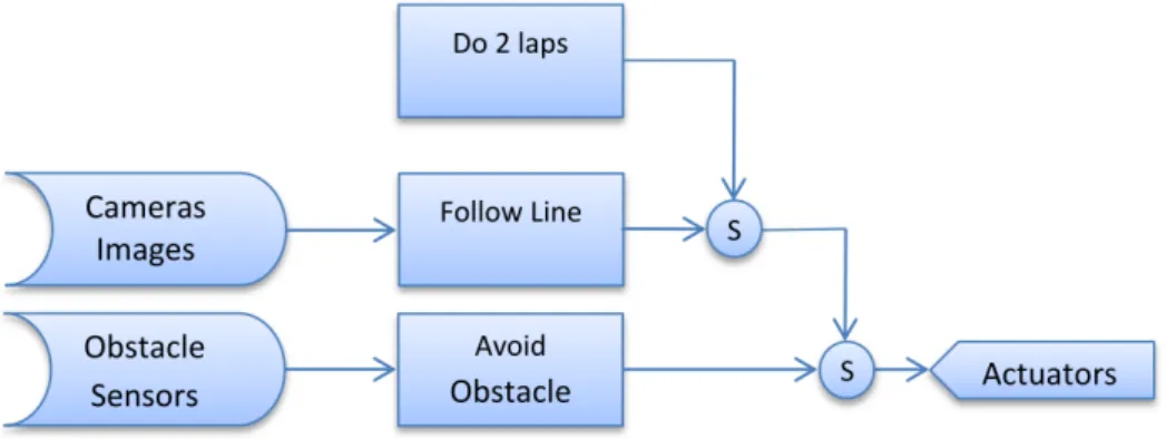
All the behaviors together in a network can recreate a model and enable the reasoning and hence planning and learning. However, behaviors should be simple as possible to maintain the ability to be reactive to environment events. Such network can be implemented using layers where the base (composed by the simplest ones) is similar to pure reactive, e.g Collision-Avoidance and the top supports the reason (the more complex). Unlike the reactive paradigm that reaches a good performance when the world dynamic is not easily extracted or predicted, the Behavior based try to learn and avoid mistakes from past looking into the future actions. An improvement in behavior representation from reactive ones is the notion of “Activation condition” and “stimuli”. The former enables the behavior and the latter acts like stimulus in reactive-behavior to select and produce an action. More than one behavior can be active at the same time (concurrency), whence behavior outputs must pass through an action selection module, as depicted in figure 2.4. There is no perfect algorithm for filtering actions, but a good selection can be determinant in the control performance.
Figure 2.4: Behavior Based
Some authors grouped behaviors in three broad categories, namely reflexive behaviors, reactive behaviors and conscious behaviors. Reactive and reflexive behaviors are a bit dif-ferent. While the reactive has a simple and very fast reasoning the reflexive is similar to a “hardwired” connection between sensors and actuators, e.g. knee-jerk reaction when a doctor hammers your knee [27,28].
2.3
System architectures
The raw material for robots has been developed over the last 50 years, and the need to joint all these pieces requires an architecture. The next pages will depict several architectures, giving an overview of the most cited in literature.
2.3.1 SPA (Sense Plan Act)
In the later 60s Nils J. Nilsson at SRI1 published a paper [29] with one of the first approaches for a robot architecture. The main objective was to build Shakey 2.5, a robot with a camera, range finder and bump sensors, to move in a real-dynamic world and to achieve some tasks. Such abilities can be found individually in robots or in some intelligent programs at that time and the author grouped them in 3 classes, Problem-solving, Modeling and Perception.
Figure 2.5: Shakey Robot [30]
The problem solving creates a sequence of primitives that lead the robot to accomplish given goals. The Modeling has the knowledge about the effects of actions and the world states that is updated by the own actions or sensor data. Finally, the Perception that, as the name implies, involves camera images and sensors processing to produce a robot understandable data and feed world, in other words retrieve relevant information from data. So, Perception sense the environment (Sense) and the Model stores the data in models (Modeling). The Problem Solving encompasses achieving a solution as well as to execute it, in other words, plan what to do, how to do and control the action in order to complete goals. Sense-Plan-Act (SPA) architecture is more cited in literature and always presented with the 5 subsets mentioned above, like depicted in figure2.6, where Perception and Modeling are parts of the sensing, while Planning, Task Execution and Motor Control are parts of the problem solving Problem Solving one [21,30].
Each level or functional unit uses only the information produced by the previous one, except the sensing that produce the first data from sensors. This turns into a sequence where each level is executed only when the previous is done.
If one of the functional units takes much time to accomplish results it makes the sequence to be delayed and consequently the robot is slower. The planner, in a real-world with lots of information cannot work in real-time, because usually has heavy processing. The planning can produce a larger set of directives and execute them. In a dynamic-world it is dangerous because no sensing shall be done at the same time in order to be responsive to events.
Figure 2.6: SPA, traditional Artificial Intelligence robot brains are serial processing units.
The SPA is a deliberative architecture since it produces a plan and then execute it without sensing until the end of the current plan.
2.3.2 Subsumption
SPA architecture has two big problems. The planning can take a long time to process and its execution without sensing in a dynamic world can be dangerous. The expansibility to complex robot of this architecture is very difficult and almost impossible. In the 80s, Brooks proposed the subsumption architecture [21], also called subsumption behavior-based or behavioral robotics. Unlike the SPA (vertical slices) the proposed architecture uses horizontal slices, and each one is usually a state machine that takes input from sensors and outputs to actuators. This state machine is often called behaviors that support the name. The paper refers some requirements and also assumptions.
The robot can achieve multiple goals, but some of them can conflict with each other and to resolve this issue a priority schema is assumed, where highest behaviors subsumes lowest ones2.7.
Figure 2.7: Subsumption layers.
A robot that moves in a real-world generally depends on multi-sensors and this introduce various errors, like the reading, transmission, out of range values, domain applicability etc. (A common question in literature is: “Under what precise conditions does the Sobel operator return valid edges?”) The robot must make decisions under these conditions of uncertainty and must continue to achieve tasks as long as possible even when something fails. This tolerance ability gives more robustness to the robot. Even when something fails the robot can operate and as long as possible achieve tasks.
A robot can be updated, for example adding more sensors, and consequently more be-haviors to use the new data are needed. Even the orderly bebe-haviors can be modified or re-arranged, but in this architecture the goal is always to expand the actual functionalities, increasing the number of behaviors. The idea is to keep components and interfaces simple, being the robot complexity a product of the environment complexity and not of the behaviors by themselves.
2.3.3 SSS
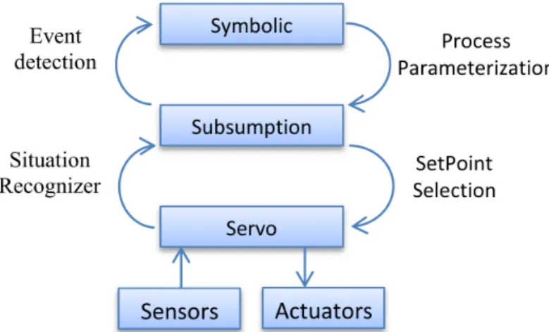
In 1992, Jonathan H. Connell described a new three layer architecture: Servo, subsump-tion, and symbolic (SSS)[31]. The objective of the project was mapping a floor and then navigates from one office to another with people and some obstacles in the way, using the TJ Robot2.8.
Figure 2.8: TalrikTMJr. AVR SSS testing
Instead of using just a behavior-based approach, like the subsumption, the control of the robot was structured into three layers (see figure 2.9). At the lowest level, there was a layer (servo layer) that dealt with lower data. It was responsible for keeping the movements smooth, controlling the wheels speed or steering and highest layer that implement the most intelligent part.
Above the servo layer there was the subsumption layer similar to the described above in the subsumption architecture. It was constituted by a set of behaviors that are selected and parameterized by the upward layer. This last layer is referred as symbolic layer and typically use events detected and created by pattern recognitions or some specific situations by the subsumption layer.
These make usage of 3 different approaches in control system, servo-like, reactive rules and discrete-time symbolic system, but the author referred that “this is not to say a good robot could not be built using just one of these technologies exclusively. We simply believe that certain parts of the problem are most easily handled by different technologies”.
This corroborates the Brooks idea, that there is no optimal solution, usually the problems should be divided in simple ones and resolve each one in an optimal way (if it exists). The difference between this architecture and the subsumption one is that Brooks argued that the reductionism applied to data to transform it in symbolic information (used here by the symbolic layer) “will lead us to solving irrelevant problems; interesting as intellectual puzzles, but useless in the long run for creating an artificial being” [32].
2.3.4 ATLANTIS
The architectures presented at this time (in the 90s) were usually based on behaviors that are described by state-machines, supported by the idea that we can describe operators onto the world model and sequence them to perform actions. Erann Gat around the same year (1992), proposed the ATLANTIS [33], acronym of A Three-Layer Architecture for Navigation Through Intricate Situations, an architecture based on action-model instead of the most popular behaviors. Action denotes two different things, the action performed by the robot in the world from the outside viewpoint, but also each action that internally composes it (from inside viewpoint) that is also called operator by the author.
When an operator is triggered, it starts a process (activity) and in the end the operator decision can trigger other operators and/or activities. If these operators network does not have any cycle, then hierarchy can be created where the high-level can initiate low-levels operators and/or activities. From outside viewpoint the robot action can be a sequence of operators and so, activities cannot be observable alone. This blinding encapsulation turns very hard the analysis of the action-model approach.
The ATLANTIS architecture is composed of three main components: the controller, the sequencer, and the deliberator or planner, as is depicted in figure 2.10. Like the other ar-chitectures presented before the control layer is responsible for execution, using the control theory applied to a set of activities created by the sequencer and ordered by the executer. The top layer is the planning and a world modeling that creates a plan to be divided in the activities by the sequencer on middle layer. Many environments properties and models are hard to represent in computational information, and, even if is possible, it can be proved that is impossible to do it in real-time. Chapman made reference to a NP problem2 in her Intractability theorem [34,35]. Thus, one of the most interesting points on this architecture is that “classical planner should be operated synchronously in conjunction with a reactive control mechanism, and the planner’s output should be used to guide the robot’s actions but not to control them directly” [33].
2.3.5 AuRA
In the 80s, Ronald C. Arkin at the Georgia Institute of Technology developed, AuRA, another hybrid architecture. In this case the deliberative and the reactive components are completely separated and some features are inspired in biologic knowledge (in books and papers of the author is commonly found neurologic expressions like “long term memory” or
Figure 2.10: ATLANTIS Architecture
“schemes”). “Fortunately, there exist excellent mobile systems (animals), provided by God, that can be studied to yield insights into the mobility problem“ [36].
AuRa is divided into 4 layers, as depicted in Figure2.11. Initially the user gives an order or goal to the Mission Planner (user intentions), and the mission planner using also some planning recognition creates a plan. The Spatial Reasoner makes use of previous knowledge stored in long term memory (e.g. maps) result of learning (spatial learning) or some previous user input (spatial goals). This produces a sequence of actions or behaviors (named by the author as schemas) which are then executed by the Plan Sequencer referred as Pilot or Driver. This sequence by virtue of opportunism can be changed or also by some user indications of mission alterations (e.g. task D becomes more important than C). The first steps are the deliberative layer of the architecture, and then the Schema Controller will execute the sequence of schemas created behind and monitors it which makes the reactive part of the architecture. The actuators controllers can adapt them to perform actions more smoothly. At this level also the user can “drive” the robot, sending orders directly to the controllers. Note that the deliberative layer is only re-done if the robot has a failure.
In 1997, Ronald C. Arkin and Tucker Balch published a review denoted “AuRA: Principles and Practice in Review” and show, in ther opinion, the strengths of the architecture, some of them very useful in development environments: “modularity, flexibility, generalizability and hybridization is the constitute the principal strengths of the Autonomous Robot Architecture” [37].
Figure 2.11: Autonomous Robot Architecture
2.3.6 Three Tiered Architecture
The Three-Tier Architecture, also called Three Layer Architecture, was developed by R. James Firby under his PhD thesis [38], but the term 3T (three Tier) only appeared in 96 by Bonasso et al [39]. The system is based on Reactive Action Packages (RAPs), also designed by the author under the PhD thesis. RAPs describes how the robot can achieve a goal as well as the available methods (for different world situations or constraints) to complete assigned tasks. The 3T have 3 distinct layers, the Deliberative or Planner, the Sequencer and the Executor, as shows the figure2.12.
The Deliberative works to create a sequence of actions to accomplish a set of objectives in a highest level of abstraction and the result should be the division in simpler and easier tasks. The Sequencer, use the planning result and selects what action from RAP must be enabled. This is also called of “RAP Interpreter” [38, 39] since the RAP can define more than one different form to do a task, depending on the circumstances. A task description is a sequence of steps and each one is a set of basic directives to be executed by the lowest layer by the RAP Executer, or only Executer, in a concurrent environment.
When a robot perform an action the reenforcement is used to give learning ability to the robot. So if the robot select a RAP that is executing and it does not produce the expected behavior, the sequencer is warned. Sequencer can also warn the deliberative part.
2.3.7 Triple-Tower Architecture
The Triple-Towers architecture was borned in the end of 90s, in fact the first reference to ”Triple-Tower” is in the book ”Artificial intelligence: a new synthesis”, but this is proposed as rough, sketchy, and not under any kind of implementation and so needs more elaboration [40]. This is based on the idea of layered architectures, where the first level deals with the data in raw format and the next levels will process the data from the descendent layer and create more abstract information, and so on [40, 41]. Abstraction and reasoning should be concurrently achieved over the time in all system and the number of levels is not specified or limited in any way. The presented architecture is focused on the hierarchy idea and makes this more a conceptual model than an architecture. The hierarchy creates the illusion of three towers, the Perception or Sensing, the Model or World Model and the Action or Behavioral Generation as is depicted in the figure 2.13 and gives Triple-Tower name.
Figure 2.13: Triple-Tower Architecture
The Learning has an important focus in the Artificial Intelligence area and the layered architectures give a better support to it because layers can be created on top of the existing ones and then increase the abstraction that somehow increases intelligence. For intelligence,
sensing, decision-making and acting are essential elements, but a better intelligence includes object and events recognition, and more abstraction that takes planning to another levels [42], and this is implemented over the highest levels.
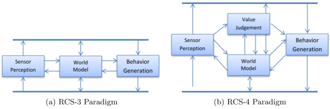
The 4D-RCS architecture and the RCS-3 and RCS-43 paradigms are the basis of the Triple-Tower Model and also a reference model for NASA4 and military unmanned vehicles [7, 27, 43]. The RCS paradigm defines the functionality of a transversal layer, i.e., a layer covering the three towers, and the two variants, RCS-3 and RCS-4, are depicted in figure2.14. It defines the functions of the modules at each tower, how they interact and how equivalent modules in adjacent layers interact.[42]. The difference between the two paradigms is the Value Judgment module, present in RCS-4 but not in RCS-3, that act as a layer supervisor. Layers are very similar in terms of architecture, and also communications flow. Thus the main difference is the order of abstraction of reasoning and so we can focus only in the architecture of one layer.
(a) RCS-3 Paradigm (b) RCS-4 Paradigm Figure 2.14: Real-Time Control System Paradigms
The communications are always between adjacent layer on each tower, but inside one layers the modules from adjacent tower also communicate. This data flows sometimes are a multi interaction, i.e., the action layer can query model and subsequently the model query the action [42].
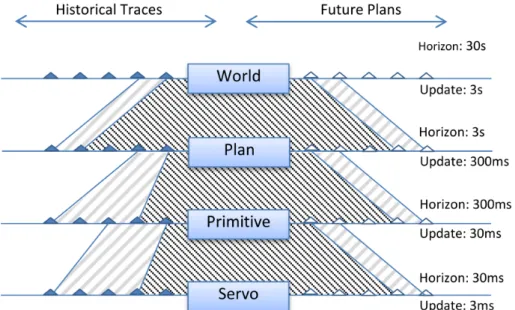
The spatial and temporal reasoning decreases about an order-of-magnitude at each higher level [42]. So other interesting viewer of the layers hierarchy is depicted in Figure2.15.
The Servo control works in a high frequency to maintain the motors with the correct angle and velocity on each order passed by the behaviors which runs at a lower frequency. This is temporal but in space the same occurs, the behavior looks more “ahead” than the servo. A planner can create a large plan in space, also thinking in long term and runs at a lowest frequency of the behaviors.
Thus, more abstract layers work at more lower frequency but process a larger window of space and tine.
3
Real-Time Control System
2.4
Conclusion
Over the last 50 years lots of architectures were proposed, created and tested, being many of them successfully re-used, some with minor variations, in different environments and/or tasks. However, most of them were created to an environment type, a kind of “situated architecture”. All were tested in a large amount of robots that implement their architecture approach. It can be concluded that both, the reactive and the deliberative control, are useful, but for different environments: the former for the highest stochastic and the other to controlled environments like factories. However, the hybrid solution can be more interesting in the general case, since it can use more or less reactivity/deliberation, while enjoying the advantages of both. The next board shows what is best in each one.
Figure 2.16: Reactive vs Deliberative
The Behavior-based is a design methodology for reactive systems that is focused in the idea of behaviorism, where the behavior is defined in terms of stimulus and response. Despite being a reactive system, it implements intelligence spread by behaviors, unlike the deliberative and hybrid that have a specific deliberative modules in its structure. The strength of Behavior based architectures is the modularity, and the intelligence created by a set of autonomous modules, which, when work together produce intelligence.
The layered architectures also gives give a better modularity, flexibility and expandability since each module / layer has an API that facilitates / makes easier the block exchange. The modular architectures give a highest extensibility to the robot and then increases team work productivity (e.g. behaviors can be produced in parallel and also easily exchanged). However, this raise a big issue: when behaviors are executed in a concurrent environment how are them selected to avoid collisions of the orders (output)? Some algorithms can be created but almost to specific situations. Using a priority approach the intersection of the behaviors output can be avoided but it is not guaranteed that the robot produces the more optimized task.
Chapter 3
ROTA Architecture
“The advantages of distributed architectures extend from improved composability, allowing a system to be built by putting together different subsystems, to higher scalability, allowing to add functionality to the system by adding more nodes, more flexibility, allowing to reconfigure the system easily, bet-ter maintainability, due to the architecture modularity and easiness of node replacement, and higher reduction of mutual interference, thus offering a strong potential to support reactive behaviors more efficiently. Moreover, distributed architectures may also provide benefits in terms of dependability by creating error-containment regions at the nodes and opening the way for inexpensive spatial replication and fault tolerance”[44].
The former ROTA’s high level software sub-system (see figure1.3) was monolithic, in the sense that there is a single thread of execution that sequentially implements the different tasks. Each execution cycle starts with the road frame acquisition. Then this frame is processed in order to extract navigation information. Next, it is decided what the next actions are and, finally, those orders are sent to the low-level software sub-system. Close to the zebra cross sign camera frame acquisition and processing are also inserted into the sequence. This approach worked nicely, but started to show some drawbacks as the complexity of the software grew up. For example, a track description and a path planning modules were developed, but are not integrated on this software due to the difficulty of integrating new modules.
During this work a new architecture for the high-level software subsystem was developed. It is based in a multi-process, multi-thread approach, using a central data store as the com-munication framework. As already stated in the Introduction, it is adapted from the software architecture of the CAMBADA’s robotic soccer team. Since the CAMBADA’s architecture was designed for a team of collaborative robots, it can also be used to allow communication between vehicles or between a vehicle and a Pit Box.
Figure 3.1gives a global overview of the proposed architecture. Each vehicle and the Pit Box act as nodes of a distributed system, supported by a wireless network. The communica-tion process, running at each node, guarantees that the shared part of the ROTA Data Base (RtDB) is replicated among all the nodes. For the typical competition, where the vehicle has to be completely autonomous, these communication facilities cannot be exploited. However, during development it can be an important aid.
Figure 3.1: ROTA architecture components
3.1
Architecture module
The modules referred in this chapter are structurally similar and can be considered as black boxes. Using a central database all the modules can be structurally modeled (from outside view point) as depicted in the figure 3.2. This definition appears in literature but only for behaviors (see section2.2.4). Although, extending this concept to all elements increase system optimization and the reasoning is consequently more efficient since it can be enable/disable or use other information to take influence in processing steps.
Figure 3.2: Generic descriptor of entities The four elements that constitute a module are described below. Activation Condition
The activation condition is used to enable or disable the activity and then processing time can be used to another tasks. In situations where lots of entities are disable it can save batteries power, e.g. disable the light signs camera and/or signs processing when
sings are not present. Stimuli / Input
The Stimuli can be from two sides, inside stimuli and outside stimuli. The internal stimulus, comes from database and is used to restrict or conditioning the process step, allowing more accurate and rapid results. For example, after an initial search, the lines in roads usually do not move much from one frame to another. The information on map can also be used to anticipate new lines or the end of the existing. The external stimulus is the input data to process, like images or sensors data.
Processing
This is the kernel of each entities. Ti is created to process data and produce an output, in other words this is the algorithm implementation part.
Output / Response
The result of processing step is stored in the database. This is then used by other entities as stimulus, or sent as orders for actuators.
3.2
Rota Data Base
The CAMBADA team from University of Aveiro has carried out some research in co-operation between robots for the middle-size robotic soccer team. The goal is to playing a soccer game in a cooperative environment, which requires coordinated actions and interaction among all the robots. The underlying of CAMBADA architecture is a distributed Real Time Database (RTDB) which keeps all the players with information from all other ones, and about the game in general. This supports dissemination of data between players and also between players and a base station that is able to send indications to the players. Since each node on the distributed database has information about the others, and the base station is also a node, it can show information about each player, acting as a monitoring tool.
The database works with abstract items that are identified by a pair of IDs, one that identifies the node and another that identifies the item inside the node. Each item is just an array of bytes that stores any information that can be shared or information local to the node. The shared data are replicated over the nodes, while the local is used only to inter-process communication within the node itself. The distribution of RTDB shared items is managed by the process, running at every node, called comm (figure 3.3). This process replicates the shared part of RTDB over the nodes with temporal information and uses a management system to schedule the traffic and improve the real-time communication and enforce timely updates of the database items, dynamically adapting to the conditions of the communication channel [45].
The RTDB is implemented in Linux OS and uses a shared memory block, which can be accessed concurrently by all the node processes. The available manipulation methods implement a copy to use strategy, i.e. instead of blocking items to prevent multiple accesses, they atomically make a copy of the desired item.
The RTDB has a simple API to create, interact and destroy the database. The initializa-tion is performed using the method DB init() and stopped using the method DB free(). There are also two simple methods to interact with items, DB put() and DB get(). DB put() is used to write items into the database. A node can only write its own shared
Figure 3.3: RtDB, a distributed database
items, i.e., the ones it produces. The others are written by the already mentioned comm process. DB get() reads items from the database. The C prototypes of the RTDB related function calls are:
int DB put( int item id, void *value);
int DB get( int node id, int item id, void *value); int DB init (void);
void DB free (void);
The initialization function of the RTDB uses a low-level configuration file to know what to do. This file describes the nodes in usage, the items at each node, their nature, shared or local, and their size in bytes. At this level, nodes and items are just numbers. At a higher level, a configuration file is used to feed a parser application, which converts a set of C++ class definitions and associated names to the abstract items of the RTDB. The names are converted to C++ macros, which makes the access to the items more user-friendly.
The RTDB definition is abstract enough to be used without any modification in the ROTA architecture. The only differences are the node names, the item names, and the classes associated to these names. However, that is managed through the configuration file and, therefore, the only work to be done in order to use the RTDB in the ROTA architecture is to write the configuration file, based on the required items (appendix A.1), and run the parser application.
3.3
Pit Box
The pit box is proposed as a node that can be an excellent aiding tool, particularly during the development phase. It is composed of an instance of the RTDB, a comm process and the Pit Box application as depicted in the figure 3.4. The latter is the main component of this node and should be a graphical application, used both to control the vehicle and to display information retrieved from the vehicle.
Figure 3.4: Pit Box and RtDB
Having access to the shared items of the RTDB, it can be used to display, over a pictorial representation of the track, perception information, like the vehicle position, the localization of the obstacles, the sign in the traffic panel, etc. Also we can have access, in real time, to the actuation orders sent by the high-level control subsystem to the low-level control subsystem. This information can be made available locally at the vehicle’s laptop, but often is uncomfortable to visualize it there, specially if the vehicle is moving. This way, the pit box can be a very convenient way to follow the vehicle’s perceptions and decisions.
Navigation of the vehicle is based on roles and behaviors. The pit box can be used to choose the vehicle’s role to be used in a given moment. For instance, it can be used to emergency stop the vehicle.
The full graphical pit box application has not been developed yet. However, it was imple-mented a simple command line application to test the Pit Box approach. It gives the ability to send orders to the car and some tests show that we can drive the car and set roles easily. Other information, like battery status, current internal states, like active behaviors and roles can also be viewed on this application.
3.4
Track Representation
The autonomous driving competition is disputed in a track that resembles a real world track (like the one described in section 1.2). To increase robot reasoning an internal repre-sentation of this track is required, e.g. to support trajectory planning. In general, a track is