DEVELOPMENT OF A RECONFIGURABLE
MULTI-PROTOCOL VERIFICATION
ENVIRONMENT USING UVM METHODOLOGY
PEDRO MANUEL AZEVEDO ARAUJODISSERTAÇÃO DE MESTRADO APRESENTADA
À FACULDADE DE ENGENHARIA DA UNIVERSIDADE DO PORTO EM
MIEEC –MESTRADO INTEGRADO EM ENGENHERIA ELECTROTÉCNICA E COMPUTADORES
F
ACULDADE DEE
NGENHARIA DAU
NIVERSIDADE DOP
ORTODevelopment of a reconfigurable
multi-protocol verification environment
using UVM methodology
Pedro Araujo
Mestrado Integrado em Engenharia Eletrotécnica e de Computadores Teacher supervisor: José Carlos Alves
Company supervisors: Luis Cruz and Domingos Terra
c
Resumo
Com o contínuo avanço da tecnologia CMOS, bem como, com o crescimento dos custos de pro-dução, torna-se cada vez mais importante produzir circuitos que cumpram todas as especificações à primeira (do it right at first time). Uma má verificação pode conduzir a que a janela de mercado se feche, enquanto se corrigem os erros detetados da primeira implementação.
O tipo de testes que têm de ser feitos para os diferentes protocolos é em grande parte similar apesar das especificidades inerentes a cada um. A metodologia de verificação UVM permite es-truturar o ambiente de verificação numa arquitectura configurável baseada em camadas, utilizando diferentes blocos genéricos. Desta forma, é possível especializar o ambiente de verificação a um dado protocolo adicionando apenas as funcionalidades necessárias à camada mais próxima do DUT (Device Under Test).
O UVM é uma metodologia que segue uma norma que foi criada pela Accellera em con-junto com os maiores fabricantes de ferramentas de desenho de circuitos electrónicos (Synopsys, Mentor, Cadence). Esta parceria pretende estabelecer uma uniformização na indústria electrónica, aumentando a eficiência do desenvolvimento e reutilização dos ambientes de verificação usados. O UVM é suportado pelas principais ferramentas de verificação/simulação de circuitos digitais, o que o torna compatível com qualquer um dos simuladores das referidas empresas. A Accellera disponibiliza para download uma API (Application Programming Interface) e uma implementação de referência (baseado numa biblioteca de classes em SystemVerilog (IEEE 1800)), que suportam o desenvolvimento de um ambiente de verificação genérico.
A dissertação emana da necessidade de reduzir o tempo de construção de um ambiente de verificação para um novo projecto. Tendo esta necessidade em consideração, a presente disser-tação foca-se na tarefa principal de desenvolver um ambiente de verificação genérico que suporte arquitectura básica de vários protocolos de comunicação, e a reconfigurabilidade necessária para suportar múltiplas configurações do mesmo DUT.
Este projecto foi sugerido pela Synopsys, uma das empresas líder na indústria da Electronic Design Automation, e foi executado no contexto do trabalho realizado pela Synopsys com proto-colos de comunicação a alta velocidade. O projecto foi realizado com as ferramentas da Synopsys para a simulação e execução de código Verilog e SystemVerilog.
O resultado do trabalho feito para esta dissertação é um ambiente de verificação genérico desenvolvido em SystemVerilog e seguindo a metodologia UVM. Juntamente com o ambiente desenvolvido, esta dissertação serve de documentação sobre as funções e classes criadas e as relações estabelecidas entre elas.
Abstract
With the ongoing progress of the CMOS technology, as well with the growing of production costs, it’s more important than ever to develop digital circuits that comply with the specifications at the first try (first time right). An incomplete verification can lead to a closing market window while the errors detected during the first implementation are still being fixed.
The sort of tests that have to be done for the different communication protocols are very similar between them, in despite of the nature of each one. The UVM verification methodology allows to structure a verification environment in a configurable architecture based on layers by using a variety of generic blocks. Thereby, it’s possible to specialize a verification environment to a given protocol just by adding the necessary functionalities to the layers closer of the DUT (Device Under Test).
UVM is a methodology that follows a standard created by Accellera jointly with the biggest companies in the industry of electronic design automation (Synopsys, Mentor, Cadence). This partnership intends to establish a standardization for verification methodologies in the electronic industry, increasing the effiency of the development and the reusability of the employed verifica-tion environments. UVM is used by the main verificaverifica-tion/simulaverifica-tion tools of digital circuits and therefore, it’s compatible with any of the simulators of the mentioned companies. Accellera pro-vides an API (Application Programming Interface) and an implementation (based on a library of classes in SystemVerilog (IEEE 1800)) which supports the development of verification environ-ments.
This dissertation stems from the need in reducing the set up time of the verification envi-ronment for a new project. By having this need in consideration, the present dissertation focus its main goal in the development of a generic verification environment that supports the core architec-ture of multiple communication protocols, and the necessary reconfigurability to support multiple configurations of the same DUT.
The project was suggested by Synopsys, one of the leading companies in the Electronic Design Automation industry, and it was performed within the scope of Synopsys’ work with high-speed communication protocols. This project will be assisted by Synopsys’ tools for the simulation and the execution of Verilog and SystemVerilog code.
The result of work done for this dissertation consisted on a generic verification environment written in SystemVerilog while following the UVM methodology. Along with the developed en-vironment, this dissertation provides a thorough documentation about the functions and classes created and the relationship between them.
Acknowledgments
This project took more than 5 months to complete, 5 months of long working hours and of some nights of short sleep. But it helped to have good people supporting me and keeping me on track, specially during the hardest times.
Inside of this circle of people, I would like first to thank the people who proposed this project in the first place: Luis Cruz and Domingos Terra. They had an incredible patience with me by answering to all my questions whenever I needed, and the help that they provided me was essential. I would also like to thank the professor José Carlos Alves, who was also part of the team and who supervisioned me during the development of the project.
I would like to give my thanks to some friends who accompanied me during the long hours spent at the office. They provided me with some good talks, which helped me to relax and to get a new perspective whenever I got stuck in some part of the project: Denis Silva, Helder Campos and Henrique Martins.
I want to include here, as well, the guys from the analog team: Bruno Silva, Hugo Gonçalves and Patricio Ferreira. Their presence during the lunch and snack breaks was the most enjoyable and their cookies, the tastiest.
And at last, but not the least, I would like to thank some special friends, friends that showed me and taught me that distance doesn’t break friendships. I would like thank Charlotte, Daniel and Fotini. They provided me with some company through some long nights, they reminded me to keep my progress reports updated and they lifted my spirits during the bad days. They were able to give the best of advices when I needed most and their support was the most important to me. Thank you.
I also want to thank all my friends who shared me with some great moments throughout this academic journey.
Pedro Araujo
“All courses of action are risky, so prudence is not in avoiding danger, but calculating risk and acting decisively. Make mistakes of ambition and not mistakes of sloth. Develop the strength to do bold things, not the strength to suffer.”
Niccolo Machiavelli
Contents
1 Introduction 1
1.1 Context . . . 2
1.2 Structure of the document . . . 2
2 State of the art 5 2.1 Hardware Description Languages . . . 5
2.2 Functional Verification . . . 6
2.3 Hardware Verification Languages . . . 8
2.4 Verification Methodologies . . . 9
2.5 The Universal Verification Methodology . . . 10
2.5.1 UVM Overview . . . 11
2.5.2 UVM Classes . . . 12
2.5.3 UVM Phases . . . 13
2.5.4 UVM Macros . . . 14
2.5.5 Typical UVM class . . . 15
2.5.6 TLM-1: Ports . . . 16
2.5.7 TLM-2.0: Sockets . . . 18
2.6 Conclusion . . . 19
3 Analysis of communication protocols 21 3.1 X-PHY Overview . . . 21
3.2 X-PHY Verification . . . 25
3.3 I2C Overview . . . 29
3.4 I2C Verification . . . 31
3.4.1 Verifying an I2C slave . . . 32
3.4.2 Verifying an I2C master . . . 35
3.4.3 UVM verification components created for the I2C interfaces . . . 36
3.5 SOC Overview . . . 37
3.6 SOC Verification Plan . . . 39
3.6.1 Testing the slave interface . . . 40
3.6.2 Testing the slave interface and the low-speed lane . . . 40
3.6.3 Testing the slave interface and the low-speed and high-speed lanes . . . . 42
3.7 Conclusion . . . 44
4 The Verification Environment 45 4.1 Testbench Overview . . . 45
4.1.1 Class table . . . 50
4.1.2 File system . . . 52
x CONTENTS
4.2 Configuration Blocks . . . 53
4.2.1 Agent configuration block . . . 53
4.2.2 Env configuration block . . . 55
4.3 The Test Block . . . 56
4.4 The Env Block . . . 57
4.5 The Agent Manager . . . 59
4.6 Generic Info Block . . . 60
4.7 Socket containers . . . 61 4.8 Agents . . . 64 4.8.1 Master Agent . . . 65 4.8.2 Slave Agent . . . 66 4.9 Broadcaster . . . 67 4.10 Monitors . . . 69 4.10.1 Master Monitors . . . 70 4.10.2 Slave Monitors . . . 71 4.10.3 Normal Monitors . . . 72 4.11 Drivers . . . 72
4.12 Scoreboard, Sequencers, sequences and transactions . . . 73
4.13 Work flow . . . 73
4.14 Conclusion . . . 74
5 Application of the Environment to the SOC 75 5.1 Verification of the SOC . . . 75
5.1.1 I2C Master Agent . . . 76
5.1.2 I2C Slave Agent . . . 79
5.1.3 Grouping the agents . . . 80
5.2 Conclusion . . . 82
6 Application of the Environment to the AC97 83 6.1 Overview of the AC97 . . . 83
6.1.1 AC-Link Interface . . . 84
6.2 Verification components . . . 86
6.2.1 Driving the inputs of the AC97 audio codec . . . 86
6.2.2 Collecting data items from the AC97’s inputs and outputs . . . 88
6.2.3 Evaluating the results of the test . . . 90
6.2.4 Agent manager . . . 90
6.2.5 Summary of the verification components . . . 91
6.3 Test cases . . . 92
6.3.1 First test: Testing the DUT’s registers . . . 92
6.3.2 Second test: Testing the Digital to Analog functionality . . . 93
6.3.3 Third test: Testing the Analog to Analog functionality . . . 95
6.3.4 Fourth test: Testing the Analog to Digital functionality . . . 97
6.3.5 Automatization of the environment . . . 98
6.4 Conclusion . . . 98
7 Conclusion 101 7.1 Summary of the developed work . . . 101
7.2 Features and results of the concluded work . . . 102
CONTENTS xi
A UVM Guide for Beginners 105
A.1 Introduction . . . 105
A.2 The DUT . . . 107
A.3 Defining the verification environment . . . 108
A.3.1 UVM Classes . . . 110
A.3.2 UVM Phases . . . 111
A.3.3 UVM Macros . . . 112
A.3.4 Typical UVM class . . . 113
A.3.5 SimpleAdder UVM Testbench . . . 114
A.4 Top Block . . . 115
A.5 Transactions, sequences and sequencers . . . 118
A.5.1 Sequence . . . 121
A.5.2 Sequencer . . . 122
A.6 Driver . . . 124
A.6.1 Creating the driver as a normal testbench . . . 126
A.6.2 Implementing the UVM driver . . . 128
A.7 Monitor . . . 131 A.7.1 TLM ports . . . 134 A.8 Agent . . . 137 A.9 Scoreboard . . . 139 A.10 Env . . . 142 A.11 Test . . . 144
List of Figures
2.1 Generic testbench . . . 6
2.2 Direct testing progress [16, p.6] . . . 7
2.3 Random testing progress [16, p.8] . . . 7
2.4 Structured testbench . . . 8
2.5 Evolution of verification methodologies . . . 10
2.6 Typical UVM testbench . . . 11
2.7 Partial UVM class tree . . . 13
2.8 Partial list of UVM phases . . . 13
2.9 Port-export communication . . . 16
2.10 Analysis port communication . . . 17
2.11 Representation of a socket communication with an initiator and a target component 18 2.12 Socket communication with an initiator, a passthrough and a target component . . 18
3.1 Applications of a possible X-PHY . . . 22
3.2 X-PHY basic lane . . . 22
3.3 States of X-PHY . . . 23
3.4 Representation of 3 different situations for a trade-off between power and perfor-mance . . . 23
3.5 X-PHY with 3 lanes . . . 24
3.6 An UVM verification environment for the receiver of X-PHY . . . 25
3.7 An UVM testbench with 2 instances of the same agent for a X-PHY device with 2 Rx . . . 26
3.8 An UVM verification environment with support for agent configuration . . . 27
3.9 An UVM verification environment with support for an agent manager . . . 28
3.10 Typical topology for an I2C interface . . . 29
3.11 Representation of a start and stop condition on an I2C bus . . . 29
3.12 Representation of an I2C read operation . . . 30
3.13 Representation of an I2C write operation . . . 30
3.14 Representation of an I2C write operation of 2 bytes . . . 30
3.15 Representation of an I2C write operation without slave acknowledgment . . . 31
3.16 Representation of a typical I2C timing diagram . . . 31
3.17 Serial and parallel interfaces created for the I2C device . . . 32
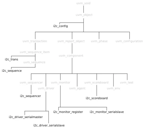
3.18 Class tree of the created components for a possible I2C testbench . . . 36
3.19 Overview of the created SOC . . . 37
3.20 Activating the low-speed lane of the SOC . . . 38
3.21 Sending sound samples to the controller . . . 38
3.22 Activating the high-speed lane of the SOC . . . 38
3.23 Sending video samples to the controller . . . 39
xiv LIST OF FIGURES
3.24 Testbench for one I2C interface . . . 40
3.25 Testbench for two I2C interfaces . . . 41
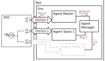
3.26 Testbench for the SOC with an agent manager . . . 42
3.27 Complete testbench for the SOC . . . 42
3.28 Testbench for the SOC with Agent Slave 2 disabled . . . 43
3.29 Testbench for the SOC with Agent Slave 1 disabled . . . 43
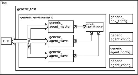
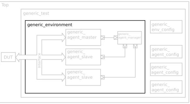
4.1 A top level view of the verification environment . . . 46
4.2 A top level view of the verification environment . . . 47
4.3 A top level view of a slave agent . . . 48
4.4 A top level view of a master agent . . . 49
4.5 A top level view of the verification environment with class names . . . 49
4.6 Class tree of the created testbench . . . 51
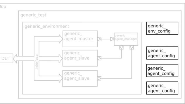
4.7 Configuration blocks of the verification environment . . . 53
4.8 Test block of the verification environment . . . 56
4.9 Envblock of the verification environment . . . 57
4.10 Agent manager block of the verification environment . . . 59
4.11 Sockets from the agent manager . . . 61
4.12 Agents of the verification environment . . . 64
4.13 A typical constitution of a master agent . . . 65
4.14 A typical constitution of a slave agent . . . 66
4.15 The broadcaster block . . . 68
4.16 The master monitor block . . . 70
4.17 The slave monitor block . . . 71
5.1 Agent for testing an I2C slave interface . . . 76
5.2 Agent for testing an I2C master interface . . . 79
5.3 Overview of the complete verification environment for the SOC . . . 80
5.4 Verification environment reconfigured for a revision of the SOC that features only one I2C-Slave . . . 80
5.5 Verification environment reconfigured for a revision of the SOC that features one I2C-Slave and one I2C-Master . . . 81
6.1 A simple model of LM4550 [14, p. 2] . . . 83
6.2 Codec Input frame of an AC-Link interface . . . 84
6.3 Codec Output frame of an AC-Link interface . . . 85
6.4 LM4550 registers highlighted . . . 92
6.5 LM4550 Testbench for the registers . . . 93
6.6 LM4550 digital to analog functionality highlighted . . . 93
6.7 LM4550 Testbench for the digital to analog functionality . . . 94
6.8 LM4550 Testbench for the digital to analog functionality with the agent manager 95 6.9 LM4550 analog to analog functionality highlighted . . . 95
6.10 LM4550 Testbench for the analog to analog functionality . . . 96
6.11 LM4550 analog to digital functionality highlighted . . . 97
6.12 LM4550 Testbench for the analog to digital functionality . . . 97
A.1 Representation of the DUT’s inputs/outputs . . . 107
A.2 Operation of the DUT . . . 107
LIST OF FIGURES xv
A.4 Partial UVM class tree . . . 110
A.5 Partial list of UVM phases . . . 111
A.6 SimpleAdder Final Testbench . . . 114
A.7 Relation between a sequence, a sequencer and a driver . . . 119
A.8 State of the verification environment after the sequencer . . . 122
A.9 Driver waveform . . . 128
A.10 State of the verification environment with the driver . . . 130
A.11 State of the verification environment after the monitors . . . 133
A.12 Port-export communication . . . 134
A.13 Analysis port communication . . . 136
A.14 State of the testbench after the agent . . . 138
A.15 Usage of FIFO in the scoreboard . . . 139
A.16 State of the testbench after the scoreboard . . . 141
A.17 State of the testbench after the env . . . 143
List of Tables
2.1 Sample code for ports and exports . . . 17
2.2 Sum up of TLM-1.0 ports . . . 18
3.1 I2C transaction . . . 33
3.2 I2C Agent Config . . . 34
3.3 I2C verification components . . . 36
3.4 I2C verification components . . . 39
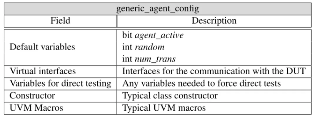
4.1 Elements of the class generic_agent_config . . . 50
4.2 Elements of the class generic_agent_config . . . 54
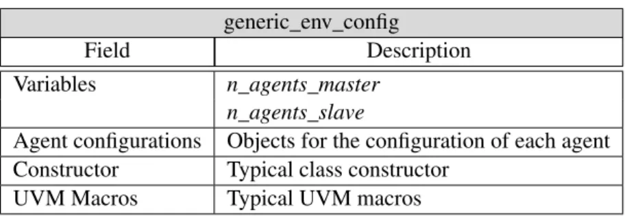
4.3 Elements of the class generic_env_config . . . 55
4.4 Elements of the class generic_test . . . 56
4.5 Elements of the class generic_env . . . 58
4.6 Elements of the class generic_agent_manager . . . 60
4.7 Elements of the class generic_info_block . . . 61
4.8 Elements of the class socket_slave_container . . . 62
4.9 Elements of the class socket_slave_container . . . 63
4.10 Elements of the class generic_agent_master . . . 65
4.11 Elements of the class generic_agent_slave . . . 67
4.12 Elements of the class broadcaster . . . 68
4.13 Elements of the class generic_monitor_master . . . 70
4.14 Elements of the class generic_monitor_slave . . . 71
5.1 I2C-Master transaction . . . 78
5.2 Verification components for the testbench of the SOC . . . 82
6.1 Transaction for generating values for the sine generator - ac97_trans_base . . . . 87
6.2 Transaction for generating values for the sine generator - ac97_trans_sine . . . . 88
6.3 Transaction for collecting transactions from the codec’s outputs - ac97_trans_ana 90 6.4 Elements of the AC97 testbench . . . 91
A.1 Sample code for ports and exports . . . 135
A.2 Sum up of TLM-1.0 ports . . . 136
Abbreviations and Symbols
API Application Programming InterfaceAVM Advanced Verification Methodology DUT Device Under Test
EDA Electronic Design Automation eRM e Reuse Methodology
HDL Hardware Description Language HVL Hardware Verification Language
IEEE Institute of Electrical and Electronics Engineers OVM Original Verification Methodology
PSL Property Specification Language PHY Physical Layer of the OSI model SOC System on a Chip
RTL Register-Transfer Level
RVM Reuse Verification Methodology TLM Transaction Level Modeling URM Universal Reuse Methodology UVM Universal Verification Methodology VHDL VHSIC Hardware Description Language VMM Verification Methodology Manual
Chapter 1
Introduction
During the last decades, electronic circuits have grown in complexity and in production costs which compelled engineers to research and develop new methods to verify the electronic design in more comprehensive, detailed and efficient ways.
The UVM methodology is one of the results of the increasing need of digital verification. It is designed in a way that allows to structure a verification environment in a reconfigurable architecture, so it can be possible to reuse components of the same environment across multiple technologies. This methodology is an industry standard recognized by Accellera System Initiative and it is comprised of a library for the SystemVerilog language (IEEE 1800) [9] and a set of verification guidelines.
One of the main advantages in reusing components from different verification environments, consists in reducing the set up time of the verification of a new project, since it isn’t needed to rebuild the reused components. Furthermore, devices that fall under the same category sometimes share similarities in their core architecture and, as a result, their verification environment can also share the same similarities. By studying these similarities, it is possible to develop a verification environment, focused in a special category of devices, which include the necessary features to be "ready to use", in a way that it is only required to add the components specific to each model while reusing the available infrastructure.
This project is targeted to a category of high-speed communication protocols developed by an EDA company, Synopsys. The purpose of this work is to take advantage of the best features of UVM and develop a reconfigurable verification environment that supports multiple communi-cation protocols with minimal development effort. The project will start with the analysis of an existing verification environment used in a specific technology by Synopsys and then followed by an analysis of the verification techniques that could be used across different protocols.
So the goals defined for this project are:
• Analysis of an existing verification environment and removal of all design logic specific to the original protocol
• Revision of the verification environment in order to support multiple protocols 1
2 Introduction
• Creation of generic blocks to support the revised environment
• Configuration and application of the generic environment to another existent protocol From this disseration, it will result a well documentated verification environment, written in SystemVerilog and using the UVM methodology, that establishes an infrastructure which covers the core architecure of the high-speed communication protocols used by Synopsys.
During the development of the project, it was also created an UVM guide for beginners to this methodology. The guide includes a technical explanation of UVM and it is accompanied by a code example to serve as an example on how to build a complete verification environment with this methodology. It can be found in the appendixAof this document.
All the information about the project and the UVM guide can be consulted in the website built for this dissertation: http://colorlesscube.com/
1.1
Context
This dissertation was proposed by Synopsys Portugal and it was carried out as part of the Master’s Degree in Electrical and Computer Engineering of the Faculdade de Engenharia da Universidade do Porto (FEUP).
The project was developed within the context of Synopsys’ work with high-speed communi-cation protocols and it is focused on devices that adopt these technologies.
Synopsys is one of the leading companies in the electronic design automation industry. Two of the most well known Synopsys’ tools include Design Compiler, a logic synthesis tool, and VCS, a Verilog and SystemVerilog compiler. The later one was used as a main tool for this dissertation. The offices of Synopsys Portugal in which this project took place are located at Maia and the the team behind the project was constituted by:
• The author of this document: Pedro Araujo • Faculty Supervisor: Professor José Carlos Alves • Company Supervisors: Luis Cruz & Domingos Terra
1.2
Structure of the document
This document presents the following structure:
• Chapter 2provides some background regarding the subjects of hardware description lan-guages, the need for hardware verification lanlan-guages, the motivation behind verification methodologies and it also provides a technical overview of the Universal Verification Method-ology.
1.2 Structure of the document 3
• Chapter3presents a study of the devices targeted by this thesis and some situations that the verification environment has to support in order to fully verifiy this category of devices. In addition, a custom device was created in order to demonstrate the features of the environ-ment.
• In chapter4, the developed verification environment is described in detail, accompanied by the documentation of each class and the explanation of the design decisions taken during the conception of the project.
• Chapter 5 represents an application of the verification environment to the custom device created in chapter3.
• Chapter6details the implementation of the same verification environment but to a different device, a model of the audio codec AC97
• Chapter7, which is the final chapter of this document, presents a summary of the developed work throughout the semester and some conclusions.
Chapter 2
State of the art
Technology has advanced a long way and become increasingly complex. Its foundations started with computers whose logic was maintained by valves and that eventually moved to microscopic devices, like transistors.
In the early beginnings, electronic systems were designed directly at the transistor level by hand, but due to the increasingly complexity of electronic circuits since the 1970s [11], it became unpractical to design the core logic directly at the transistor level, so circuit designers started to de-velop new ways to describe circuit functionality independently of the electronic technology used. The result was the Hardware Description Languages and the era of Electronic Design Automation was born.
Hardware description languages are languages that are used to define the behavior and the structure of digital integrated circuits before they are translated into their own architecture. These kind of languages enable the modeling of a circuit for posterior simulation and, most importantly, translation into a lower level specification of physical electronic components.
A hardware description language resembles a typical programming language, it consists in a textual description of expressions and control structures and although they both share some sim-ilarities, they are not the same. One main difference is that HDL code is translated concurrently, which is required in order to mimic hardware, and while programming languages, after compi-lation, are translated into low level instructions for the CPU to interpret, HDL specifications are translated to digital hardware, so using hardware description languages requires a different mind-set than using programming languages.
Nowadays, hardware description languages are the prevailing way of designing an integrated circuit, having superseded schematic capture programs in the early 1990s, and became the core of automated design environment. [13, p.15-1]
2.1
Hardware Description Languages
VHDL and Verilog are the two most popular HDL standards. [5] Verilog was created as a propri-etary language by Phil Moorby and Prabhu Goel between 1983 and 1984 and it is formally based
6 State of the art
in the C language. Cadence bought the rights of the language in 1989 and made it public in 1990. Eventually, IEEE adopted it as a standard in 1995 (IEEE 1364) [7].
On the other hand, unlike Verilog which was originally designed to be used as a proprietary tool, VHDL was intentionally designed to be a standard HDL. It was originally developed on behalf of the U. S. Department of Defense between 1983 and 1984 but only released in 1985. It is based on Ada programming language and it was adopted as a standard IEEE 1076 [8] in 1987. [13, p.15-3]
2.2
Functional Verification
Hardware description languages are tools that help engineers to easily specify abstract models of digital circuits to translate them into real hardware, but after the design is complete, another issue becomes noticeable: how can a designer know that the design works as intended?
This brings up the need for verification. Verification is defined as a process used to demonstrate the functional correctness of a design. [4, p.1] This process is done by the means of a testbench, an abstract system that provides stimuli to the inputs of the design under verification (DUV) and analyzes its behavior. A verification environment is represented in the figure2.1.
Device
Under
Veri cation
Testbench
Figure 2.1: Generic testbench
One of the most common uses of a testbench is to show that a certain design implements the functionality defined in the specification. This task is known as functional verification. Normally, the testbench implements a model of the functionality that the designer wants to test and it is responsible to compare the results from that model with the results of the design under test. But it is important to take into account that functional verification can show that a design meets the specifications that have been verified but it cannot prove it. [4, p.2]
2.2 Functional Verification 7
The traditional approach to verification relies on directed test. Verification engineers conceive a series of critical stimulus, apply them directly to the device under test (DUT) and check if the result is the expected one. This approach makes steady progress and produces quick initial results because it requires little effort for setting up the verification infrastructure. So given enough time, it maybe possible to write all the tests needed to cover 100% of the design. This scenario is represented in the figure2.2.
100%
Time
Coverage
Figure 2.2: Direct testing progress [16, p.6]
But as the design grows in size and complexity, this becomes a tedious and a time consuming task. Most likely, there will be not enough time to cover all the tests needed in a reasonable amount of time and there will be bugs that the verification engineer won’t be able to predict. So, random stimuli help to cover the unlikely cases.
However, in order to use random stimuli, there is the need of automating a process to generate them and there is also the need of a block that predicts, keeps track of the results and that analyzes them: a scoreboard. Additionally, when using random stimulus, it will be needed to check what cases were covered by the generated stimuli, so the testbench will need functional coverage as well. Functional coverage is the process of measuring what space of inputs have been tested, what areas of the design have been reached and what states have been visited. [16, p.13]
This kind of testbench requires longer time to develop, causing an initial delay in the start of the verification process. However, random based testing can actually promote the verification of the design by covering cases not achieved with directed tests, as seen in the figure2.3
100% Time Coverage Directed Test Random Test
8 State of the art
2.3
Hardware Verification Languages
In the previous section, it was mentioned some features that a verification environment must have: a stimulus generator, a functional coverage block, a scoreboard. However, it needs a block to drive the generated stimulus to the DUT and a block that listens to the communication bus, so that the responses of the DUT can be driven to the scoreboard block and to the functional coverage block. A representation of this structured testbench can be seen in the figure2.4.
DUT Testbench Driver Monitor Stimulus Generator Scoreboard Functional Coverage
Figure 2.4: Structured testbench
As testbenchs grow and become more complex, the verification process might be a more re-source consuming task than the design itself. Today, in the semiconductor industry, verification takes about 70% of the design effort and the number of verification engineers is twice the number of RTL designers in the same project. After a project is completed, the code of the testbench takes up to 80% of the total volume code. [4, p. 2]
As the circuit complexity grows, the verification process increases in complexity as well and become a very important and critical part of the project. However, the typical HDL aren’t able to cope with the complexity of today’s testbenches. Complex data structures, application of con-straints to the random stimulus, presence of multiple functional blocks and functional coverage, are all examples of features that aren’t available in the standard HDLs used for specification, namely in Verilog and in VHDL, as these more focused in creating a model of a digital design than programming verification. [10]
In order to solve this problem, Hardware Verification Languages (HVL) were created. The first one to be created was Vera in 1995. It was an object-oriented language, originally propri-etary, designed for creating testbenchs for Verilog. The language was bought in 1998 by Synopsys and released to the public in 2001 as OpenVera. OpenVera has support for high-level data struc-tures, constraint random variables and functional coverage, which can monitor variables and state transitions, and Synopsys also added support for assertions capabilities.
In 1997, a company named Verisity created the proprietary language e. Like OpenVera, it is also object-oriented and feature-wise, it is very similar to Vera.
2.4 Verification Methodologies 9
IBM also developed its own verification language, Property Specification Language. It is more narrower than OpenVera or e and it is designed to exclusively specify temporal properties of the hardware design. [10]
Eventually, the features of some languages like, OpenVera and PSL, were merged to Verilog and it was created a new language, SystemVerilog. SystemVerilog supports a variety of operators and data structures, as well constrained random variables, functional coverage checking and tem-poral assertions. This new language was adopted as a standard IEEE 1364 in 2005 [7] and is now the most used verification language in the industry. [13, p. 15-17]
2.4
Verification Methodologies
The adoption of verification languages eased the process of verification but there was no consen-sus in the proper use of a verification language. In the attempt of helping to deploy the right use of a verification methodology, Verisity Design (now Cadence Design Systems) published in 2000 a collection of the best practices for verification targeted to the users of e language. Named vAd-visor, it just consisted in a package of verification patterns in HTML format and it covered many aspects like coverage modeling, self-checking testbenches and stimuli creation. [12, p. xvii] In 2002, the same company revised vAdvisor and created the first verification library, the e Reuse Methodology (eRM). It was a big step because it included fundamental examples like sequences, objection mechanisms and scoreboards. [17]
In order to compete with Verisity Design, Synopsys presented in 2003 the Reuse Verifica-tion Methodology (RVM) for Vera verificaVerifica-tion language. The most notable contribuVerifica-tion of RVM was the introduction of callbacks, that was inspired from software design patterns and adapted to verification languages. Eventually, RVM was ported from Vera to SystemVerilog to create the Verification Methodology Manual (VMM). [12, p. xviii]
Until this point in time, both verification methodologies had been proprietary and it was only in 2006 that it was introduced the first open source verification methodology, the Advanced Veri-fication Methodology (AVM) from Mentor Graphics. [6] This library incorporated the concept of Transaction-Level Modeling from SystemC.
In 2005, after the acquisition of Verisity, Cadence started, as well, to port eRM to the standard of hardware verification languages, SystemVerilog. The result was the open source methodology, Universal Reuse Methodology (URM) in 2007.
However, in the joint task of merging the best features of each methodology, in 2008, Cadence and Mentor Graphics integrated both URM and AVM into a single open source methodology, the Open Verification Methodology (OVM). This collaborative effort ended up to be a good solution, because not only unified the libraries and the documentation but also, due to the open source nature, users could make their own contributions to the methodology. [12, p. xvii]
10 State of the art
Later on, Accellera group decided to adopt a standard for verification methodologies and OVM was chosen as basis for this new standard and together, with Synopsys’ VMM contributions, a new methodology was created: the Universal Verification Methodology (UVM). [1] A sum up of the evolution of verification methodologies is represented in figure2.5.
2000 2002 2004 2006 2008 2010 vAdvisor eRM RVM VMM AVM URM OVM UVM
Figure 2.5: Evolution of verification methodologies
2.5
The Universal Verification Methodology
The UVM methodology is provided as an open-source library directly from the Accellera website and it should be compatible with any HDL simulator that supports SystemVerilog, which means it is highly portable. UVM is also based on the OVM library, this provides some background and maturity to the methodology. These two points are two of the main reasons for industry approval of the methodology.
Another key feature of UVM includes reusability. In a traditional testbench, if the DUT changes, engineers would redo the testbench completely. This process takes some effort but most of the times, if the testbench is correctly programmed, some blocks of it could be reused for the new testbench.
On other occasions, under the same DUT, verification engineers might want to apply a different test or change the kind of stimuli sent to the DUT. If the engineer doesn’t take in mind that the test might change, he might end up revising the entire testbench. The lack of portability and documentation of the testbench might lead to a complete revision of the testbench without any margin for reusability.
UVM also addresses these kind of situations and specifies an API and guidelines for a standard verification environment. This way, the environment is understood by any verification engineer that understands the methodology and it becomes easily modifiable.
2.5 The Universal Verification Methodology 11
2.5.1 UVM Overview
The structure of an UVM environment is very similar to the testbenches mentioned previously. It features the most common components, like monitors, drivers and scoreboards, as well other classes that help to standardize testbenches across applications. A typical UVM environment is represented in the figure2.6.
Top
Sequencer
Monitor
Driver
Scoreboard
DUT
Agent
InterfaceEnv
Test
Figure 2.6: Typical UVM testbench
In the represented testbench, there is a device under test (DUT) and it is intended to interact with it in order to test its functionality, so there is the need to stimulate it. To achieve this, there will be a block, that generates sequences of data to be transmitted to the DUT, named sequencer. Information about the sequencer can be found in the appendixA.5.
Usually sequencers are unaware of the details of the communication protocol, and are respon-sible for generating generic sequences of data to another block that handles the communication with the DUT. This block is called the driver. The appendixA.6 details the functionality of the driver.
While the driver maintains activity with the DUT, by feeding it data generated from the se-quencers, it doesn’t do any validation of the responses to the stimuli. The testbench needs another block that listens to the communication between the driver and the DUT and that evaluates the responses from the DUT. This block is the monitor. More information about the monitor can be consulted in the appendixA.7.
Monitors sample the inputs and the outputs of the DUT, they try to make a prediction of the expected result and send the prediction and result of the DUT to another block, the scoreboard,
12 State of the art
in order to be compared and evaluated. More information about the scoreboard can be read in the appendixA.9.
The components of the UVM environment communicate between each other by using the Transaction Levelcommunication. This communication will be address later in sections2.5.6and
2.5.7.
All these blocks constitute a typical system used for verification and it is the same structure used for UVM testbenches. Usually, sequencers, drivers and monitors compose an agent. An agent and a scoreboard compose an environment. All these blocks are controlled by a higher level block denominated test. The test block controls all the blocks and sub-blocks of the testbench. This means that just by changing a few lines of code, it is possible to add, remove and override blocks in the testbench and build different environments without rewriting the whole test.
To illustrate the advantage of this feature, imagine a situation where a DUT that uses SPI for communication is being tested. If, by any chance, we want to test a similar DUT but with I2C instead, it would just need to add a monitor and a driver for I2C, and override the existing SPI blocks, while keeping the sequencer and the scoreboard.
The current section gave an overview about the composition of an UVM environment. How-ever, a deeper explanation of the UVM API will be provided in the following sections:
• The section2.5.2will explain the most important classes of the methodology • The phases of each class will be described in section2.5.3
• Each class has functionalities that are implemented by the usage of macros and the section
2.5.4will explain the most important ones
• The section2.5.5illustrates the code for a generic UVM component
• The sections2.5.6and2.5.7refer to the Transaction Level communication between compo-nents
2.5.2 UVM Classes
The example from chapter 2.5.1 demonstrates one of the great advantages of UVM. It is very easy to replace components without having to modify the entire testbench, but it is also due to the concept of classes and objects from SystemVerilog. In UVM, all the mentioned blocks are represented as objects that are derived from the already existent classes.
2.5 The Universal Verification Methodology 13
A class tree of the most important UVM classes can be seen in the figure2.7. [2] uvm_void uvm_object uvm_report_object uvm_transaction uvm_sequence_item uvm_sequence
uvm_phase uvm_con guration
uvm_component uvm_sequencer uvm_driver uvm_monitor uvm_agent uvm_scoreboard uvm_env uvm_test
Figure 2.7: Partial UVM class tree
The data that travels to and from our DUT will stored in a class derived either from uvm_sequence_item or uvm_sequence. The sequencer will be derived from uvm_sequencer, the driver from uvm_driver, and so on.
Each of these classes already have some useful methods implemented, so that the designer can only focus on the important part, which is the functional part of the class that will verify the design. These methods are detailed in the next sections.
2.5.3 UVM Phases
All the mentioned classes in chapter2.5.2have simulation phases. Phases are ordered steps of execution implemented as methods. When a new class is derived, the simulation of the testbench will go through these different steps in order to construct, configure and connect the testbench component hierarchy.
The most important phases are represented in figure2.8. [1, p.48] build_phase
connect_phase
run_phase
report_phase
14 State of the art
• The build phase is used to construct components of the hierarchy. For example, the build phase of the agent class will construct the classes for the monitor, for the sequencer and for the driver.
• The connect is used to connect the different sub components of a class. Using the same example, the connect phase of the agent would connect the driver to the sequencer and it would connect the monitor to an external port.
• The run phase is the main phase of the execution, when the actual code of a simulation will execute.
• The report phase is the phase used to display the results of the simulation.
There are many more phases but none of them are mandatory. If a particular class is not needed, it is possible to omit it and the compiler will just ignore it.
2.5.4 UVM Macros
Another important aspect of UVM are the macros. These macros implement some useful methods in classes and in variables. They are optional, but recommended. The most common ones are:
• ‘uvm_component_utils - This macro registers the new class type. It is usually used when deriving new classes from uvm_component.
• ‘uvm_object_utils - This macro is similar to the macro ‘uvm_component_utils but it is used with classes derived from uvm_object.
• ‘uvm_field_int - This macro registers a variable in the UVM factory and implements some functions like copy(), compare() and print().
• ‘uvm_info - This is a very useful macro to print messages from the UVM environment during simulation time.
• ‘uvm_error - This macro is responsible for sending messages with an error tag to the output log.
These are the most used macros, their usage is the same for every class, but there are more macros available in the UVM API. [2, p. 405]
2.5 The Universal Verification Methodology 15
2.5.5 Typical UVM class
A typical UVM class has the structured listed in code2.1. 1 c l a s s g e n e r i c _ c o m p o n e n t e x t e n d s uvm_component ; 2 ‘ u v m _ c o m p o n e n t _ u t i l s ( g e n e r i c _ c o m p o n e n t ) 3 4 / / ∗∗∗∗∗∗∗∗∗∗∗∗∗∗∗∗∗∗∗∗∗∗∗∗∗ 5 / / ∗∗ V a r i a b l e s 6 / / ∗∗∗∗∗∗∗∗∗∗∗∗∗∗∗∗∗∗∗∗∗∗∗∗∗ 7 / / The v a r i a b l e s n e e d e d f o r t h e c l a s s go h e r e 8 9 / / ∗∗∗∗∗∗∗∗∗∗∗∗∗∗∗∗∗∗∗∗∗∗∗∗∗ 10 / / ∗∗ C o n s t r u c t o r 11 / / ∗∗∗∗∗∗∗∗∗∗∗∗∗∗∗∗∗∗∗∗∗∗∗∗∗
12 f u n c t i o n new ( s t r i n g name , uvm_component p a r e n t ) ; 13 s u p e r . new ( name , p a r e n t ) ; 14 e n d f u n c t i o n : new 15 16 / / ∗∗∗∗∗∗∗∗∗∗∗∗∗∗∗∗∗∗∗∗∗∗∗∗∗ 17 / / ∗∗ P h a s e s 18 / / ∗∗∗∗∗∗∗∗∗∗∗∗∗∗∗∗∗∗∗∗∗∗∗∗∗ 19 f u n c t i o n v o i d b u i l d _ p h a s e ( uvm_phase p h a s e ) ; 20 s u p e r . b u i l d _ p h a s e ( p h a s e ) ; 21 / / Code f o r c o n s t r u c t o r s g o e s h e r e 22 e n d f u n c t i o n : b u i l d _ p h a s e 23 24 f u n c t i o n v o i d c o n n e c t _ p h a s e ( uvm_phase p h a s e ) ; 25 s u p e r . c o n n e c t _ p h a s e ( p h a s e ) ; 26 / / Code f o r c o n n e c t i n g c o m p o n e n t s g o e s h e r e 27 e n d f u n c t i o n : c o n n e c t _ p h a s e 28 29 t a s k r u n _ p h a s e ( uvm_phase p h a s e ) ; 30 / / Code f o r s i m u l a t i o n g o e s h e r e 31 e n d t a s k : r u n _ p h a s e 32 33 f u n c t i o n v o i d r e p o r t _ p h a s e ( uvm_phase p h a s e ) ; 34 / / Code f o r s h o w i n g s i m u l a t i o n r e s u l t s g o e s h e r e 35 e n d f u n c t i o n : r e p o r t _ p h a s e 36 e n d c l a s s : g e n e r i c _ c o m p o n e n t
Code 2.1: Code for a generic component
The line 2 presents the macro for registering the component in the UVM environment, lines 11 to 13 represent the class constructor used to initialize the objects and variables from the class, and from line 18 is placed the functions and the tasks for the UVM phases described in section
16 State of the art
2.5.6 TLM-1: Ports
The first step in verifying a RTL design is defining what kind of data should be sent to the DUT. While the driver deals with signal activities at the bit level, it does not make sense to keep this level of abstraction as we move away from the DUT, so the concept of transaction was created.
A transaction is a class object, usually extended from uvm_transaction or uvm_sequence_item classes, which includes the information needed to model the communication between two or more components.
Transactions are the smallest data transfers that can be executed in a verification model. They can include variables, constraints and even methods for operating on themselves. Due to their high abstraction level, they are not aware of the communication protocol between the components, so they can be reused and extended for different kind of tests if correctly programmed.
An example of a transaction could be an object that would model the communication bus of a master-slave topology. It could include two variables: the address of the device and the data to be transmitted to that device. The transaction would randomize these two variables and the verification environment would make sure that the variables would assume all possible and valid values to cover all combinations.
Now, another question arises: how are transactions transported between components? The answer is: through TLM. Transaction Level Modeling is a high-level approach to modeling com-munication between digital systems. TLM provides a set of comcom-munication interfaces that can be used to connect different components at the transaction level by isolating them in the environ-ment. This promotes reusable components and minimizes the time required to build a verification environment. [3, p. 9]
There are two kinds of TLM communication interfaces: TLM-1 and TLM-2.0. This chapter will focus on TLM-1 but more information about TLM-2.0 can be consulted later on chapter2.5.7. The TLM-1 is represented by two main aspects: ports and exports. A TLM port defines a set of methods and functions to be used for a particular connection, while an export supplies the implementation of those methods. Ports and exports use transaction objects as arguments.
Figure2.9is possible to see a representation of a TLM-1 connection.
producer consumer
top class
Figure 2.9: Port-export communication
The consumer implements a function that accepts a transaction as an argument and the pro-ducer calls that very function while passing the expected transaction as argument. The top block connects the producer to the consumer.
2.5 The Universal Verification Methodology 17
A sample code is provided in table2.1.
class topclass extends uvm_component; . . .
function void connect_phase(uvm_phase phase); . . .
producer.test_port.connect(consumer.test_export) . . .
endfunction; endclass;
class producer extends uvm_component; class consumer extends uvm_component; uvm_blocking_put_port#(test_transaction) test_port; uvm_blocking_put_imp#(test_transaction,
consumer) test_export;
. . . .
task run(); task testfunc(test_transaction t);
test_transaction t; //Code for testfunc() here...
test_port.testfunc(t); endtask
endtask
endclass endclass
Table 2.1: Sample code for ports and exports
The class topclass connects the producer’s test_port to the consumer’s test_export using the connect()method. Then, the producer executes the consumer’s function testfunc() through test_port.
A particular characteristic of this kind of communication is that a port can only be connected to a single export. But there are cases when we might be interested in having a special port that can be plugged into several exports.
A third type of TLM port, analysis port, exists to cover these kind of cases.
An analysis port works exactly like a normal port but it can detect the number of exports that are connected to it and every time a required function is asked through this port, all other components whose exports are connected to an analysis port are going to be triggered. Figure2.10
represents an analysis port communication.
producer
consumer1 top class
consumer2
18 State of the art
The usage of analysis ports is very similar to normal ports, so it is not provided a code example like in the table2.1. However, a brief summary of these ports and exports can be seen in the table
2.2.
Table 2.2: Sum up of TLM-1.0 ports
Symbol Type Port declaration
Port uvm_blocking_put_port #(transaction) port_name Export uvm_blocking_put_imp #(transaction, classname) export_name Analysis Port uvm_analysis_port #(transaction) analysis_port_name
2.5.7 TLM-2.0: Sockets
In chapter2.5.6, TLM-1 ports were analyzed but they have two major disadvantages: they don’t support bi-directional communication and they don’t have passthrough objects. To solve these problems, a new kind of connection was created: TLM-2.0, most known as sockets. A socket is very similar to a port or an export, as it is derived from the same class, but it provides a forward and a backward path. [3, p. 24]
A socket connection starts with a component that has initiator sockets and ends with another component that has target sockets. Initiator sockets can only connect to target sockets and vice-versa and each socket can only have a maximum of one connection. The figure2.11represents a typical socket connection between a target and a initiator.
Initiator Component Target Component Forward Path Backward Path
Figure 2.11: Representation of a socket communication with an initiator and a target component It is also possible to implement passthrough socket in case it is desirable to relay the message from a component to a subcomponent. This situation is represented on figure2.12.
Initiator Component Target Component Initiator-passthrough socket Target-passthrough socket
Figure 2.12: Socket communication with an initiator, a passthrough and a target component These two cases represent the situations that will be using during the execution of this project.
2.6 Conclusion 19
2.6
Conclusion
Verification plays a big role in the conception of digital integrated circuits. Manual test cases are not enough anymore to do a thorough verification of a digital design, so verification languages and verification methodologies were created in order to assist engineers to test even the more unlikely cases.
The current chapter presented an analysis to functional verification and to verification method-ologies, and presented the most essential material used for the development of this thesis. A more extensive explanation of UVM can be found in the Appendix A, this should provide an extra explanation of some concepts talked over the next chapters.
Chapter 3
Analysis of communication protocols
Nowadays, electronic consumer devices are more popular than ever, it is a trend in constant grow-ing and in great market need. One of the most popular electronic devices are the smartphones. A smartphone is a small, battery operated, highly sophisticated computing and communication device. These are actually, one of the major market drivers for low power consumption and high performance devices. So hardware designers need to take these aspects in mind during the devel-opment of the hardware.
One of the aspects that can be improved in electronic devices in order to reduce its power con-sumption is the efficiency of the interconnection between their internal components, for example, between a camera and the CPU or the modem and the antenna. An ideal system-on-a-chip must incorporate multiple high speed peripherals for inter-chip communication, while maintaining a low power consumption. In response to this need, there have been many developments to optimize communication interfaces at the physical layer for mobile applications.
3.1
X-PHY Overview
This thesis will focus on technologies developed by Synopsys for high-speed communication pro-tocols. As the specific details of these technologies must remain confidential, we will use a generic term denominated of X-PHY to refer them.
The physical layer, commonly known as PHY, is the lowest layer of the OSI model. It is the bridge between the physical medium and the link layer, so it is the ideal place to optimize power consumption. A PHY serves as the base for other protocols at the higher layers that deal with other purposes, such as data storage, data transfer, interaction with displays, etc. An optimized physical layer for mobile applications, let’s assume X-PHY, could replace some of the communication interfaces of other technologies in order to reduce the power consumption while preserving the characteristics of that technology. The X-PHY is considered as a serial communication interface in which the data is sent through differential pins.
22 Analysis of communication protocols
An example of the uses of X-PHY can be seen in the figure3.1.
Physica
l
Layer
X-PHY
M-PCIe
UniP
ro
CSI-2
P
rotocol
Layer
Application
Camer
a
PCI E xpr ess Storage (U F S)Figure 3.1: Applications of a possible X-PHY
In order to support a technology like PCI-Express on a mobile environment, a protocol layer, like the M-PCIe, can be implemented on top of X-PHY. The usage of X-PHY as the physical layer instead of the PCI Express PHY, could mean optimization in power consumption for mobile applications while still providing a high-speed interface.
Another advantage of X-PHY besides an optimized power consumption, is the low pin count. The most basic unit of the X-PHY is the lane, which can be a transmitter (TX) or a receiver (RX), and each lane it is represented with just a pair of differential pins. This can be seen on the figure
3.2.
Tx
Rx
Lane 0
Device A
Tx+Device B
Tx-Rx+3.1 X-PHY Overview 23
As a consequence of preserving power, each lane supports multiple states. These states repre-sent a trade-off between power and performance and can be dynamically adapted to the situation’s need. The states of X-PHY are represented in figure3.3.
Power Ratio Sleep Low Speed High Speed Stall
Figure 3.3: States of X-PHY
For data transmission, there are two main states, Low-Speed (LS) and High-Speed (HS). This availability of multiple power modes, allows the designer to have some versatility on the approach to the relation between the best performance and power consumption. This means that X-PHY allows for situations where it is demanded a constant high-speed communication without caring for power saving modes, as well for situations where it is important to preserve power.
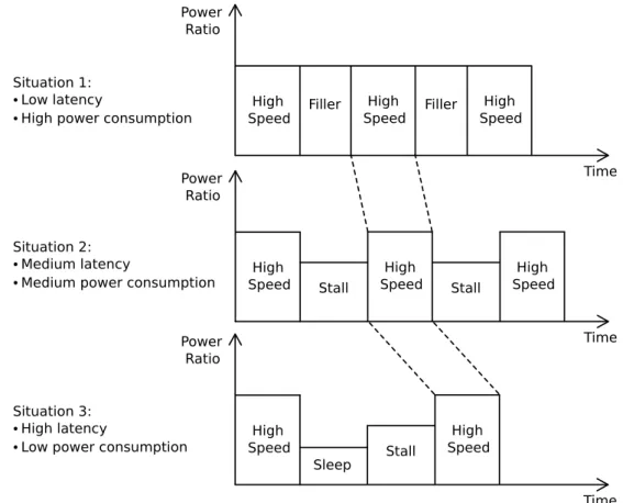
The figure3.4 represents 3 different situations that trade-off latency in communication with power saving modes.
Power Ratio High Speed Stall High Speed Stall High Speed Time Power Ratio High Speed Filler High Speed Filler High Speed Power Ratio High Speed Stall High Speed Sleep Time Time Situation 1: ⦁ Low latency
⦁ High power consumption
Situation 2: ⦁ Medium latency
⦁ Medium power consumption
Situation 3: ⦁ High latency
⦁ Low power consumption
24 Analysis of communication protocols
The situation 1 represents a situation where a constant high-speed communication is important without taking in account power saving features. In this scenario, the interface fills the transmis-sion with filler data in order to keep the high speed states even during periods of no data trans-mission, making the communication more responsive. As a drawback, this causes a higher power consumption.
To reduce it, instead of filling the gaps with filler data, the X-PHY can enter in a stall state that saves up more power. The change of states, causes a small latency between the transmissions of frames and thus making the communication less responsive. This is represented by situation 2.
The situation 3 represents a case even more optimized for power. After a frame has been transmitted in high-speed, the interface goes into the sleep state, a state that can save more power than stall. This introduces a higher latency because the interface, before going into the high-speed state again, has to leave the sleep state and go through the stall state.
All these cases refer to operations with just one lane but X-PHY also supports multiple lanes simultaneously. The operation mode with just the basic lane configuration states the basic func-tionality of X-PHY and the configurations with multiple lanes add a common block shared by all of them that manages all the lanes’ states, this block is denominated of Lane manager.
The figure3.5represents a possible situation of X-PHY with more than just one lane.
Tx
Rx
Lane 0
Tx
Rx
Lane 1
Device A
Device B
Rx
Tx
Lane 2
Lane
manager
Lane
manager
Tx+ Tx-Rx+ Rx-Tx+ Tx-Rx+ Rx-Tx+ Tx-Rx+Rx-Figure 3.5: X-PHY with 3 lanes
Another possible scenario would be 3 transmitters and 3 receivers on the same device, or even just 4 receivers. Although all these lanes don’t share the same bus, they are dependent of each other. For example, there may exist cases when the Lane 1 must be inactive while Lane 2 is transmitting, or when Lane 3 is going to high-speed and all other low-speed lanes must switch to high-speed too. This behavior is controlled by the lane manager.
All these situations were mentioned in order to understand the kind of configurations that a verification environment has to support. These include: single lanes supporting multiple states; multiple lanes being dependent of the states of other lanes; add or remove lanes dynamically in order to test the behavior of the PHY with multiple configurations. An I2C or SPI interface are much simpler and don’t need all this kind of complexity. An ideal verification environment would provide the necessary infrastructure to deal with the described situations.
3.2 X-PHY Verification 25
3.2
X-PHY Verification
The main functionality of X-PHY was analyzed and with that analysis it is possible to take an approach of a possible verification environment. At its essential level, a verification environment emulates the functionality of the device under testing (DUT) and compares the result with the DUT’s behavior.
Taking into account the figure the 3.2, the Device B (the receiver part) is considered as a DUT for the situation that will follow. A testbench for this DUT, would need a component that stimulates the device, a driver, and it would need a component that listens to the serial line in order to emulate the functionality that we want to test, a monitor. It would also need another monitor that would watch over the DUT’s behavior and a component that would compare the result from the DUT and from the testbench, a scoreboard.
Testing a simple configuration like this is quite simple. The X-PHY is a communication pro-tocol, so the basic functionality that the testbench needs to verify is if the data got correctly inter-preted by the device. The testbench would compare the data obtained through the monitor watch-ing the serial line with the data interpreted by the DUT and it would look for any mismatches.
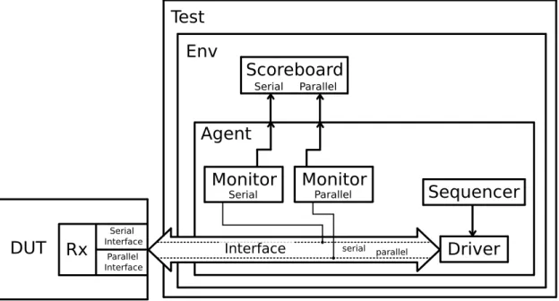
Figure3.6represents an UVM environment that can be used to build the described testbench.
Rx
Serial Interface Parallel Interface
Interface serial parallel
Driver
Sequencer
Monitor
SerialMonitor
ParallelAgent
Scoreboard
Serial ParallelEnv
Test
DUT
Figure 3.6: An UVM verification environment for the receiver of X-PHY
As we are testing the Rx interface, the testbench will emulate the Tx side of the communi-cation. This analysis to the verification of X-PHY will focus mostly on the receiver part, but the process is the same for the transmitter.
The sequencer is responsible for feeding transactions to the driver and it shouldn’t be con-nected to any other block except to the driver, because only the monitors are responsible for the evaluation of the DUT’s functionality, although the sequencer can hold information about the type
26 Analysis of communication protocols
of transactions that should be sent to the environment.
The UVM User’s Guide from Accellera [3, p.4] describes the agent as an abstract container, that encapsulates a driver, a sequencer and a monitor, with the purpose of emulating the DUT. These three blocks act independently in the testbench. And by putting them in a container, it becomes easier to reuse them for other situations.
In order to demonstrate reusability, it is going to be assumed that the DUT now features two similar, but independent, Rx interfaces. In order to verify the functionality of the second Rx interface, we just need to duplicate the agent and the scoreboard. The figure 3.7represents this scenario.
Rx
Serial Interface Parallel InterfaceInterface serial parallel
Driver
Sequencer
Monitor
SerialMonitor
ParallelAgent
Scoreboard
Serial ParallelEnv
Test
DUT
Rx
Serial Interface Parallel InterfaceInterface serial parallel
Monitor
SerialMonitor
ParallelDriver
Sequencer
Agent
Scoreboard
Serial ParallelFigure 3.7: An UVM testbench with 2 instances of the same agent for a X-PHY device with 2 Rx
It is possible to notice that for this situation, the scoreboard is always closely related to the agentso it would make sense to put it together with the monitors, the driver and the sequencer.
3.2 X-PHY Verification 27
It is now considered different DUTs: a DUT with one Rx interface (figure 3.6) and another DUT with two Rx interfaces (figure3.7).
A typical testbench would keep two separate Env blocks, an Env with only one agent and an-other Env with two agents, but this would mean managing two separate tests. The ideal testbench would be able to adapt itself to these two situations without reworking the whole environment. To achieve this, each agent will feature a configuration block that will enable or disable the respective agent depending on the device being tested.
This new verification environment is represented on figure3.8.
Rx
Serial Interface Parallel Interface
Interface serial parallel
Driver
Sequencer
Monitor
SerialMonitor
ParallelAgent
Scoreboard
Serial ParallelEnv
Test
DUT
Rx
Serial Interface Parallel InterfaceInterface serial parallel
Monitor
SerialMonitor
ParallelDriver
Sequencer
Agent
Scoreboard
Serial Parallel
Agent
Config
Agent
Config
Figure 3.8: An UVM verification environment with support for agent configuration The new agent config block will allow for a reconfigurable verification environment and with just one line of code, in the test class, it will be possible to disable and enable agents manually. This is useful for verifying DUTs like X-PHY that can have different configurations, as seen in figures3.2and3.5.
28 Analysis of communication protocols
Each agent now is composed by a driver, a sequencer, two monitors, a scoreboard and a con-figuration block. This is enough to test a simple interface individually: the sequencer generates the necessary sequences to be sent to the DUT and the driver takes care of the communication with the device by emulating the X-PHY’s states and transmission frames. Meanwhile, the monitors take care of collecting transactions from the communication to be evaluated by the scoreboard.
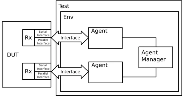
But if it is intended to test a DUT in which the lanes depend on each other, the testbench will have to support a block that manages multiple agents at the same time in order to emulate the same functionality. This is represented on figure3.9.
Rx Serial Interface Parallel Interface Env Test DUT Rx Serial Interface Parallel Interface Interface Agent Interface Agent Agent Manager
Figure 3.9: An UVM verification environment with support for an agent manager
The agent manager will be connected to the drivers and to the monitors of each agent and it will consist of a state machine that controls transmission requests from all the lanes.
As an example, assuming a hypothetical situation that in the DUT there is a resource shared by both interfaces, like a clock generator, and assuming that the change of states of each lane would depend on the system clock, the lane manager would control the access to this shared resource, thus controlling the change of the states of each lane.
This would mean that if both lanes are transmitting in the high-speed state and one of them would want to change its state to low-speed, this lane would first make a request to the lane manager and the lane manager in its turn would check for the usage of the shared resource and give permission, or not, for the lane to change its state.
The envisioned testbench would support for multiple configurations just by changing a few lines of code. The presence of an agent manager also allows for a dynamic reconfiguration of the testbench during the execution of the test.
In order to demonstrate some of these features, it will be developed a device that will emulate the features of PHY. For this device, it will be used an I2C interface instead of the interface X-PHY. The following section will start with a brief overview of the I2C protocol before presenting the example device.