F
ACULDADEDEE
NGENHARIA DAU
NIVERSIDADE DOP
ORTODevelopment of GUI Test Coverage Analysis
and Enforcement Tools
Ricardo Daniel Ferreira Ferreira
F
INALV
ERSIONReport of Dissertation
Master in Informatics and Computer Engineering
Supervisor: João Carlos Pascoal de Faria (PhD)Development of GUI Test Coverage Analysis and Enforcement Tools
Ricardo Daniel Ferreira Ferreira
Report of Dissertation
Master in Informatics and Computing Engineering
Approved in oral examination by the committee:
Chair: António Augusto de Sousa (Associated Professor)
____________________________________________________
External Examiner: José Francisco Creissac Freitas Campos (Auxiliary Professor)
Internal Examiner: João Carlos Pascoal de Faria (Auxiliary Professor)
24
thAbstract
Software applications are becoming more and more important in today's society. From them depends the functioning of critical systems in several areas. To interact with these systems were developed graphical user interfaces (GUIs). These interfaces are more attractive to the user allowing to use the functionalities of the system with ease.
Tests are needed to assure the reliability of the systems and increase the confidence on its correct functioning. The application can have several elements to be tested. One of them is the GUI. Inside this, faults have to be discovered whether they are in the code of the interface or simply usability faults.
However GUI testing is hard. The GUIs can contain very complex controls, endless sequences of actions and many states. They also have code behind that needs to be tested too. Even when this code is automatically generated, it can contain errors.
There are several approaches for GUI testing. Model-based testing is the one that offers more advantages in automatic test case generation and execution. This technique requires the definition of an abstract model of the system under test (SUT), from which test cases can be generated. We can evaluate the quality of the test cases and then apply them to the SUT.
To evaluate the quality of the tests, coverage criteria are defined. They allow to get a value that is the coverage degree of the tests over the application or the model. This degree of coverage can intervene in test generation process. When this coverage degree has a required value, the test generation can stop.
There are some tools that ease the model-based testing process. Each tool use a different modelling notation to represent the system. From the tools found and presented in this report, none of them have model coverage analysis feature.
The work developed fits into the area of GUI testing. It is presented a survey of coverage criteria applied to models and a model coverage analysis tool that addresses and presents visually the model coverage achieved by a given test suite.
The model supported by the tool use UML notation, namely UML state machines. This notation was chosen because it is a standard and because it is easily interpreted by other people. To assess differences between some notations, it was created a simple system and tested it using the different notations.
The tool developed receives an UML model and several test cases. The tool then executes the model according to the test cases and indicates which elements were exercised by the test cases. In case the model was not fully covered, the tester can add tests to assure maximum coverage of the model.
This tool represents an improvement over existing MBT tools because they usually lack a coverage analysis feature.
Resumo
As aplicações de software são cada vez mais importantes no dia-a-dia. Delas dependem o bom funcionamento de sistemas cada vez mais cruciais em diversas áreas. Para que possa ser possível interagir com estes sistemas foram desenvolvidas interfaces gráficas. Estas interfaces gráficas são mais apelativas para o utilizador permitindo que utilize as funcionalidades do sistema com maior facilidade.
Para que as aplicações sejam fiáveis, aumentando a confiança do utilizador na aplicação, é necessário realizar testes sobre a mesma. A aplicação poderá conter vários elementos a serem testados. Entre os elementos a serem testados encontra-se a interface gráfica. Nesta, terão de ser procuradas e solucionadas falhas que a interface possa conter quer a nível conceptual quer a nível de usabilidade.
Porém, o teste de interfaces gráficas ainda não é facilmente exequível. Estas podem conter controlos bastante complexos, inúmeras sequências de acções e imensos estados possíveis. Ainda, as interfaces gráficas contêm código integrado que também deverá ser testado. Mesmo quando este código é automaticamente gerado pode conter erros.
Para avaliar a qualidade dos testes, são definidos critérios de cobertura permitindo obter um valor que corresponderá ao grau de cobertura dos testes sobre a aplicação. O grau de cobertura poderá intervir na geração de casos de teste no sentido em que poderá parar a geração de casos de teste quando o grau de cobertura for o pretendido.
Entre as técnicas de teste de interfaces disponíveis actualmente, o teste baseado em modelos é o que melhor se enquadra quando o tema é geração e execução automática de casos de teste. Esta técnica permite uma definição do sistema em forma de um modelo abstracto. A partir dos testes sobre o modelo poderemos aferir a qualidade dos casos de teste e aplicá-los então ao sistema a testar.
Existem então algumas ferramentas que auxiliam o processo de utilização de teste baseado em modelos. As ferramentas utilizam diferentes tipos de modelação do sistema. De entre as ferramentas encontradas e referenciadas nesta dissertação, nenhuma delas apresenta análise da cobertura do modelo por parte dos casos de teste gerados.
O trabalho foi desenvolvido no âmbito do teste de interfaces. Para isto, propõe-se a apresentar critérios de cobertura aplicáveis a modelos e também a criar uma ferramenta que permita fazer uma análise da cobertura dos modelos de entrada.
Quanto aos modelos, foram escolhidos modelos em notação UML nomeadamente os modelos de máquinas de estado. Esta notação foi escolhida por ser um standard da indústria e pela sua fácil interpretação por terceiros. Para aferir diferenças entre algumas notações de modelação foi criado um sistema que foi testado utilizando diferentes tipos de modelos.
A ferramenta desenvolvida deverá receber o modelo UML e vários casos de teste e indicar, pintando, no modelo original quais foram os elementos visitados pelos casos de teste. No caso de não ser completamente coberto, poderão ser adicionados mais testes e verificada a sua cobertura sobre o modelo.
Esta ferramenta traz vantagens sobre as actualmente existentes visto que pretende colmatar uma falha existente nas ferramentas actuais, permitindo obter uma análise da cobertura do modelo através da sinalização dos seus elementos.
Acknowledgements
I would like to thank my supervisor, Professor João Carlos Pascoal de Faria, from Engineering Faculty of Porto University, for his guidance, determined search of resources, unforgettable mentoring and encouragement that made this dissertation possible.
A special thank to my co-supervisor Professor Ana Cristina Ramada Paiva Pimenta, also from Engineering Faculty of Porto University, for her inputs, enthusiasm and his invaluable perceptiveness in the discussions we had.
I owe special thanks to André Grilo and Nelson Rodrigues, for the suggestions, feedback, the time we spent working together, and the talk he gave here in Engineering Faculty of Porto University.
I wish to express my gratitude to my parents and sister, Sebastião Ferreira, Laura Maia and Laura Ferreira, for all their support, care, comprehension, and love. Thank you.
Contents
1 Introduction... 1
1.1 Context... 1
1.2 Motivations and goals... 2
1.3 Dissertation's structure... 2
2 GUI testing processes... 3
2.1 Introduction... 3
2.2 Manual testing process... 4
2.3 Script-based process... 5
2.3.1 Keyword-driven testing... 7
2.3.2 FIT... 7
2.3.3 Data-driven testing... 8
2.4 Capture/replay testing... 8
2.5 Model-based testing process... 9
2.6 Conclusions... 12
3 Models, coverage criteria and tools for model-based testing...13
3.1 Models... 13
3.1.1 State-transition models... 13
3.1.2 Pre/post models... 14
3.1.3 Other modeling notations... 14
3.2 Coverage criteria... 15
3.2.1 Structural model coverage... 15
3.2.2 Data coverage... 16
3.2.3 Fault model criteria... 18
3.2.4 Standard testing checklists... 18
3.3 Tools for MBT... 19
3.4 Conclusions... 20
4 Experimentation and comparative assessment... 21
4.1 System requirements... 21
4.2 UML state machine model... 21
4.2.1 Test cases derived from the UML model (using transition coverage)...22
4.3 Pre/post model... 23
4.3.1 Manually derived test suite from pre/post model (using condition/ decision coverage)... 23
4.3.2 Automatically generated test suite from pre/post model (using transition coverage) ... 24
4.4 Comparative assessment... 24
4.4.1 Assessment criteria... 24
4.4.2 Comparative assessment... 25
5 Development of a model coverage analysis tool... 27
5.1 Context, objectives and requirements... 27
5.2 Tool overview... 28
5.3 Working principle... 29
5.4 Enterprise Architect model organization... 29
5.5 Instructions to use the application... 31
5.6 Internal structure... 35
5.7 Algorithms and important technologies used... 38
5.7.1 LINQ... 38
5.7.2 Model transformation... 38
5.7.3 Model coverage analysis algorithm... 39
5.7.4 Expression representation and evaluation... 39
5.8 Input file structure... 40
5.9 Conclusions... 41
6 Conclusions and future work... 43
References... 45
Appendix A Common user interface errors... 49
Appendix B Manually defined test suite for UML model... 53
Appendix C Pre/post model of the alarm specification... 55
Appendix D Algorithm to check model coverage... 59
List of Figures
Figure 2.1: Notation used in the following figures [UtL06]... 4
Figure 2.2: Manual testing process [UtL06]... 5
Figure 2.3: Manual scripting process [UtL06]... 6
Figure 2.4: Keyword-driven testing process [UtL06]... 7
Figure 2.5: Capture/replay process [UtL06]... 9
Figure 2.6: Model-based testing process [UtL06]... 11
Figure 3.1: Integer boundary points of a complex domain... 17
Figure 3.2: Steps for button testing [Baz09]... 18
Figure 3.3: Elevator control sample included in ParTeG tool... 20
Figure 4.1: UML alarm class... 22
Figure 4.2: State machine diagram of alarm system... 22
Figure 4.3: Exploded UML model of the alarm system... 23
Figure 4.4: FSM of the alarm system... 24
Figure 5.1: AMBER iTest project... 28
Figure 5.2: Organization of the input model... 30
Figure 5.3: Import/Export menu in Enterprise Architect... 31
Figure 5.4: Export dialog in Enterprise Architect... 32
Figure 5.5: Initial window of the application developed... 32
Figure 5.6: Load files in the application... 32
Figure 5.7: Save file in the application... 33
Figure 5.8: Import dialog in Enterprise Architect... 33
Figure 5.9: Fully covered UML model... 34
Figure 5.10: Partially covered UML model... 34
Figure 5.11: Package diagram of the application... 35
Figure 5.12: Model package class diagram... 36
Figure 5.13: Test Suite package class diagram... 36
Figure 5.14: Parser package class diagram... 37
List of Tables
Table 2.1: ActionFixture table sample... 8
Table 4.1: Coverage of empirical test objectives in the approaches used (V-fully covered, P-partially covered, X-not covered). Numbers in parenthesis indicate section numbers...25
Table 5.1: Use of LINQ to XML... 38
Table 5.2: Treatment given to after event... 39
Table 5.3: Sample of expression, its RPN notation and return value... 39
Abbreviations
ASM Abstract State Machine
FIT Framework for Integrated Testing FSM Finite State Machine
GUI Graphical User Interface GUITAR GUI Testing frAmewoRk LINQ Language INtegrated Query MBGT Model-Based GUI Testing MBT Model-Based Testing MTC Model Test Coverage OCL Object Constraint Language ParTeG Partition Test Generator PIN Personal Identification Number RPN Reverse Polish Notation SQL Structured Query Language SUT System Under Test
UML Unified Modeling Language UTP UML Testing Profile XMI XML Metadata Interchange XML eXtensible Markup Language
1 Introduction
Graphical User Interfaces (GUIs) are the most used interface for software, providing user-friendly access to the functionalities of the system by responding to user events such as mouse movement, menu selections, etc.. With the widespread use of this kind of interface, the construction of increasingly complex GUIs is becoming frequent. As they make software easy to use, they also make software development process more difficult [BrM07, MSP01].
As it is an important part of the system, GUIs must also be tested for a better confidence in the application developed. Due to the very close relation between the final user and the GUI of the application, GUI testing is an important issue because its defects can drastically influence user's impression about the overall quality of the system developed.
Testing GUIs is not an easy task because of its flexibility and variety. They also have an enormous amount of different permutations of events and interactions possible that can be executed by the user. Even when tools automatically generate the GUI, they are not bug free and can cause the system to fail. To effectively test a GUI, it is important to understand how tests can be abstracted to ensure resilience and cost-effective test automation [BDG07]. As the GUIs are mostly event-driven, usual testing techniques cannot be used [MeS03].
To assess the adequacy of some test suite, coverage criteria have to be defined. Coverage criteria are a set of rules that help determining the quality of a test suite. Coverage criteria can also be used to guide the test generation process. But, for GUI testing, not all coverage criteria can be used. For example, code-based coverage criteria cannot address some interactions between the events that the user performs in the application and the system.
For GUI testing, some techniques have to be defined. One of them is model-based testing (MBT). This technique will be the main theme of this dissertation and will be compared to other GUI testing approaches.
There are inclusive some tools developed that uses MBT to test GUIs. A short list of available tools that uses MBT for GUI testing will be presented.
1.1 Context
Software testing is gaining more and more importance. With the crescent complexity, size of the software, and reduced development cycle times, more systematic and automated approaches are being seek. Model-based testing (MBT) techniques are beginning to be more and more used by software developers and test designers. MBT presents several advantages with respect to other approaches like manual testing and capture/replay testing [UtL06]; the main advantage is that test cases are generated and executed automatically from a model that
Introduction
specifies the intended behavior of the system under test (SUT). However, to ensure the generation of adequate test suites, it is important that the test generation process is guided by appropriate coverage or quality criteria.
Tools using model-based testing are being created to automate as much as possible GUI testing, diminishing the testing effort and associated costs. Current tools do not present solutions to all the problems that GUI testing has (such as model coverage analysis).
This dissertation was done as a part of the research project AMBER iTest – An Automated Model-Based User Interface Testing Environment. The project is being developed by FEUP with collaboration of Critical Software (CSW). The final goal is the development of a pack of tools and techniques to automate specification-based GUI testing. The project also intends to be innovative, complementing the tools actually existing.
1.2 Motivations and goals
GUI testing is becoming more important since the arrival of GUIs. The GUIs allow the user to interact with the application in a higher level of abstraction. Actual tools using MBT cannot address all the problems presented by GUI testing. The main goal of this research work is to improve GUI testing tools, so the GUIs can be better tested, presenting a better quality when delivered to final user. More specifically, the work reported in this dissertation addresses two problems already referred: the identification of appropriate coverage criteria for the models and the development of a tool that feedbacks the user about model coverage achieved by a test suite.
The main goals of this dissertation are:
• Analyze and identify coverage criteria for model-based GUI testing. Since model coverage criteria is strongly related to the kind of model used, the work also involves the identification and analysis of models for model-based GUI testing;
• Develop a tool that analyze and represent visually the coverage of model's elements achieved by a given test suite.
1.3 Dissertation's structure
Beside this introduction, this thesis is structured as follows:
• In section 2 , the state of the art in approaches to develop tests for GUIs is presented. The comparison between approaches presented help justifying why MBT is gaining more and more strength actually;
• In section 3 , the most important kinds of modeling notations, coverage criteria and tools are presented;
• Section 4 presents an example of an alarm system to practically evaluate characteristics of the modeling notations and coverage criteria;
• Section 5 describes the tool developed, showing how it works, its architecture and algorithms and cares to take when creating both the model and the test suite to use as input of the application;
• The last section presents the conclusions and future work;
• Appendix A refers GUI interface errors usually encountered in practice;
• Appendix B shows the test suite manually derived from the UML model of the system defined in section 4 ;
• Appendix C shows the code using Spec# to implement the system defined in section 4 ;
• Appendix D demonstrates the algorithm used in the tool developed to check the coverage of the model against a test suite;
• Appendix E shows a portion of the XML file that describes the model to be imported by Enterprise Architect and the application developed.
2 GUI testing processes
This chapter describes testing techniques that can be used to perform GUI testing. The concepts and implementation methods of each technology are presented as well as the main advantages and disadvantages of each one.
2.1 Introduction
Testing software can be seen as a search problem. We will search among the infinite possibilities of input combinations available to be performed, those that cause the system to fail and those that do not.
The main goal of software testing is to produce a set of tests that, as exhaustively as practically possible, test the System Under Test (SUT) with normal or exceptional behaviors which are specified by complete and correct requirements definition. Completeness requires that enough aspects of our system are specified and correctness means that there are no ambiguities, errors or inconsistencies within requirements [BDG07].
In [Wag04], the author refers that there are a lot of problems of GUI testing. The main problems that the author refers are:
• It is hard to test GUIs with hybrid complex architectures;
• GUIs are changing for usability issues and the tests needs to be modified every time the GUI presents some change;
• Unsolicited events that can occur can interrupt a sequence of commands without notice and at any time;
• Window management operations (resize, move) can also cause bugs;
• The GUI is almost always platform-independent and the tests are also difficult to support multiple platforms;
• Interface design issues is an important factor in GUI's quality.
When testing the functionality of the SUT, we should consider some key steps that are important to be followed to achieve a good testing process. Those are [UtL06]:
• Design Test cases: all test cases should be designed in the beginning, taking in account
system requirements and the test objectives. Each test must have a context and pass/fail criteria. Along with the test design, the test conditions for each test item, detailed test approach and associated test cases are identified [IEE98].
• Execute tests and analyze results: The test cases are tested on the SUT or in some
model that includes SUT’s functionalities, depending on the approach. The result of tests are written in a Test Results document that will be later analyzed to see which tests
GUI testing processes
have passed or failed and, for those who failed, determine the cause of test execution failure and correct them.
• Verify test coverage: To achieve a good quality of the tests we must have some metrics
on how well tests cover all functionalities included in the SUT. In GUI testing it is normally used requirements coverage by the test suite, done through a traceability matrix between requirements and test cases.
Some GUI testing techniques that can be used to test the GUI of applications will be presented next, showing the differences between each approach, its advantages and disadvantages.
Figure 2.1 shows the notation used in following diagrams to better understand them.
2.2 Manual testing process
This process is the oldest, but still, most of the tests are done manually [UtL06]. Figure 2.2 shows the phases of a manual testing process.
The “Test Plan” is an overview of which parts of SUT are to be tested, how often tests will be executed and the approaches to be used.
The test design phase is done manually, based on informal Requirements and Test Plan. In this phase, the test designer should document, in a human readable manner, the tests that are going to be performed in the SUT by the manual tester. This phase is a very time-consuming task and does not ensure a systematic coverage of SUT’s functionality.
After test design is complete and the SUT is ready for testing, the tester executes manually the tests defined previously, interacting directly with the SUT. Then, the actual output is compared to the expected output to check if the test passes or fails. The results of each test case are written on a Test Results document for further analysis.
The skills required from the test designer and the tester are completely different. While the test designer needs to have knowledge in test design strategies and know the SUT well, the tester only needs to know how to interact with the SUT to follow the steps defined in test case and record the output of the test.
Once a new release of the SUT needs to be tested, the tester will execute manually all tests against the SUT. This becomes a very boring, error-prone and time-consuming task, because testers can sometimes unintentionally leave some tests untested and others tested several times. It’s very time-consuming since the testing time is high and always the same on each new release
GUI testing processes
of the SUT. To keep costs within the budget stipulated, on each new release, some tests that were executed previously are not executed because they are not related with the modified portion of code. The main intention of this strategy is to reduce the test cases to be applied. With this approach, the SUT becomes incompletely tested and some unexpected errors can occur, affecting product stability and robustness.
Test coverage metrics are also computed manually. A manual analysis has to be done to ensure that all logical combinations were tested, requiring lots of time, effort and a very good knowledge of the SUT and its functionalities.
Although it is a totally manual process, it is widely used to test essentially the business logic because it is harder to teach it to machinery than for the testers to learn the logic. Intuition plays also a big role in these situations. Manual testers also have the time to see small business logic errors [Wit08].
2.3 Script-based process
All automated processes of testing are based on some kind of script. Scripts can run against the SUT with proper tools that will interpret the lines contained on the script file and translate them into actions to be performed in the SUT. So, in the execution test phase, human interactions with the SUT are unnecessary.
In [BBN04], the authors refer that all test scripts typically have a predefined sequence of steps that:
• Initializes the SUT;
• Loops through a set of test cases, and for each of them:
Figure 2.2: Manual testing process
[UtL06].
GUI testing processes
◦ Initializes the SUT (optional);
◦ Sets the input;
◦ Execute the SUT;
◦ Captures the output of the SUT and compares it to the expected output storing the results for further analysis.
Scripts have an advantage when test execution is to be done repeatedly because it saves a lot of time requiring only computational effort to run the tests. The processes described in the next sections use scripting to automate test execution. In the simplest way, scripts are generated manually. Techniques to generate scripts automatically will be discussed in later sections.
In Figure 2.3 we can see a diagram explaining how manual scripting usually works. The test design phase is the same as in the manual testing process. The difference comes in a later phase when executing the tests. Instead of having a tester manually testing the SUT, we have a programmer that will implement the test script manually. This process automates the test execution and further executions of the tests.
Most of the time required to perform the tests will be in the implementation phase where the programmer would have to write all test cases into the script manually, requiring some special skills to do it.
This approach has also some maintenance problems because if the application is changed, the script will have to be changed too. As the script can be very extensive and complex, the places where we need to change can be difficult to find and it can be a time-consuming, costly and error-prone task.
Figure
2.3: Manual scripting
process [UtL06].
GUI testing processes
2.3.1 Keyword-driven testing
Keyword-driven testing is basically another manner to structure the script. Action keywords are used in the definition of the test cases. Each action keyword relates to a fragment of the test script. The “Adaptor” code in Figure 2.4 converts the action keyword into the respective code so the test execution tool understands it, raising the level of abstraction. Each test case will be nothing more than action keywords and test data.
The implementation of these keywords still requires programming skills, but the design of test cases is now at a higher level allowing other people that are not programmers to write the test cases (although programmers need to implement the adaptor code).
2.3.2 FIT
Framework for Integrated Testing (FIT) is a testing framework that promotes collaboration between the development team and the customer. It allows to know what the software actually does and describes what it should do. The main purpose of FIT is to write acceptance tests that could be validated by the customer [Cun07].
With this framework, the customer can write an HTML table with some tests and the expected result. The table is then analyzed by a “fixture” that programmers implement and then FIT tools like FitNesse [FiN09] will paint the cells of the table with green or red colors depending if the test performed against the SUT passes or fails respectively.
There are different kinds of tables that can be created. ColumnFixture is a kind of table where the first column of each row has the attribute or method and the following rows contain the test cases. Each row is executed column by column until the end of the row.
Figure 2.4: Keyword-driven testing
process [UtL06].
GUI testing processes
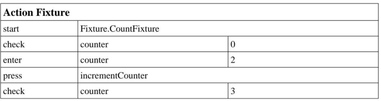
The other kind of table is the ActionFixture (Table 2.1) where each table represents a sequence of actions that together define a test case. Each ActionFixture can correspond to a user story. ActionFixtures have 4 commands although more can be defined. The predefined commands are: start that has the name of the class to start the feature, enter that executes a method with parameters, press that executes a method with no parameters and check that verifies the result of a method with no parameters. In user interface, enter action can be programmed for example to insert text in a text box; press can be used to click a button and check to see the result presented in a label.
This technique also requires programming skills as it requires that the mapping code between the application and the instructions defined in the table are implemented. This technique can be seen as a special case of keyword-driven testing.
Table 2.1:
ActionFixture table sample.
Action Fixture
start Fixture.CountFixture check counter 0 enter counter 2 press incrementCounter check counter 32.3.3 Data-driven testing
Data-driven testing is the parameterization of test scripts allowing different data to be introduced to the same test procedure. With one test procedure and a data file, we can have several test cases, all differing in data values given to the attributes/methods. This makes test scripts more generic and can be applied in a lot of test cases, reducing test script maintenance problems. This approach does not require any tool except the one who will merge the data with the tests that are included in the test script. This approach can be used with keyword-driven testing, allowing the definition of more test cases with less effort.
2.4 Capture/replay testing
The capture/replay testing process allows the capture of actions performed to the SUT and saves them in a script file. Later, when testing the SUT, the tool will repeat exactly the same steps on the SUT. The actions are performed manually by a tester and the tool records the actions, inputs and outputs. This script can be edited to refine test cases, but this requires some skills from the person who edits the file.
When re-executing the tests, the test execution tool will read the script, set the inputs, execute the actions on the SUT and compare the output to the previously saved output.
The tests will be executed exactly the same way as initially saved. So the time needed to perform the tests the first time is the same as in manual testing. The advantage of this approach comes in further testing of the SUT because there is no need to execute them manually. The tool executes the tests and then gives the feedback about the tests that passed and failed.
This technique is very fragile because if some change occurs in the layout of the SUT the test will fail. This can happen because the tool expects the control in one place and it does not appear there or another control appears in its place or no control appears at all. Then the tests that are affected by the change need to be saved again manually so it can work in the next
GUI testing processes
release. So, its inability to adapt to small changes in the SUT creates a maintenance problem, causing this technique to be abandoned in many situations.
In Figure 2.5 we see all the steps of capture/replay testing. In the bottom of the figure we can see that the manual tester interacts with the tool recording the test cases for further use.
An example of a tool that does that is Selenium tool [Sel09]. This tool is only for testing web pages, but the concepts to test other kinds of applications are the same. To begin the test process, the tester starts the saving process. This process will save every action performed by the user including clicks and text writing. To verify if the test has completed successfully, the tool supplies ways to check the contents of a page, verifying if some word or expression is there. The tool also manages several test cases and gives feedback about those who have failed and those who have completed successfully. This will allow seeing the number of tests failed and where they have failed also. This tool has support for several browsers and can export the test suite to several programming languages and testing frameworks like JUnit [JUn09].
2.5 Model-based testing process
Model driven development plays actually a major role in reducing time and budget of software development because it introduces techniques such as automated software production [BDG07]. As models are helping in the software production, model-based testing appears as the equivalent for software testing.
Model-based testing is the automatic generation of tests, derived whole or in part from a model representing system's requirements and functionalities [WikiMBT, MBT09].
When the system has a large amount of input and state combinations, previous approaches turn to be impotent at this scale. The approaches used must systematically find relevant combinations according to defined criteria (because most of the time it is impossible to generate all the combinations of states and inputs). The approach needs also to be focused to ensure that
Figure 2.5: Capture/replay process
[UtL06].
GUI testing processes
all the information available is used wisely to seek the source of common errors and automatic to ensure that a large amount of tests are generated and re-tested when necessary.
Model-based testing ensures all the three objectives. The number of tests that are performed is still very small in comparison with the space of inputs and states, but it is much larger than the tests that can be designed/run manually.
Binder refers in his book that “Automated testing replaces tester’s slingshot with a machine gun. The model paints the target and casts the bullets” [Bin00].
Model-based testing is also dependent on scripting, but it aims to automate all phases of testing processes: test case design is done by a Test Case Generator tool that can have different test selection criteria, test case implementation is done by Test Script Generator executing the tests into the SUT and finally the verification of test output and analysis of expected values.
In MBT, the function of the test designer is to generate a simplified model of the SUT instead of test case design, and then, tools will automatically generate and run test suites depending on test selection criteria, reducing both the time of test design and execution of the tests.
As shown in Figure 2.6, MBT is divided into five different phases:
1. Model: This phase consists in writing an abstract model of the SUT that should be
much smaller and simpler than the SUT. It must focus on the key aspects that we want to test and omit many of the details of the SUT. The model will be iteratively refined until all the behaviors desired are implemented and correct. The model can have some requirement identifiers to document the relations between the model and requirements. Besides helping in analysis of requirements coverage in a later phase, this will help to clarify the requirements and check if all requirements intended to be tested are actually implemented in the model. After writing the model and before generating test cases, it is convenient to check the consistence of the model and if it has the expected behavior using tools such as type checkers and animators.
2. Generate: This step generates abstract test cases from the model, taking in account
defined test selection criteria that restricts the usually infinite possibilities of test cases. For example, we could be interested in testing only some part of the model, or choose between different coverage criteria. From this phase we should get a set of abstract test cases consisting on a sequence of operations generated from the model. Since the model is a simplified view of the SUT, these tests are not directly executable in the SUT because it lacks some details needed. The details will be added automatically in the next phase.
Another output that could be generated in this phase is the requirements traceability matrix and other coverage reports. The requirements traceability matrix links the requirements and test cases. This will allow seeing if all requirements have been covered by test cases. Coverage reports consist in values that explain how well the behaviors of the model have been tested.
These reports could be also used to identify parts of the model that aren’t well covered by test cases. In this situation, we can try changing some test selection criteria and repeat the test case generation again and see if the problem was solved. In an extreme case, we can add some test case by hand to exercise one specific path of the model that has not been exercised by the automatically generated test suite.
3. Concretize: The next step in MBT implementation is to concretize the abstract tests
into executable tests. This is done by a Test Script Generator tool that uses mappings and templates to translate the abstract tests into executable tests which are then saved in a test script. So, the main goal of this step is to fulfill the gap between abstract tests and the SUT, adding some details needed that are not present in abstract tests.
The distinction between abstract tests and concrete tests is actually useful because abstract tests can be independent of the language used to write the tests. By changing some “Adaptor” code and/or translation templates, we can use the same tests on
GUI testing processes
multiple environments. Other advantage is that the skills required to add abstract tests are fewer because these tests can be in a high-level language.
4. Execute: This phase will execute the concrete tests into the SUT. There are now two
approaches to do this. The first is online model-based testing which consists in executing the tests at the same time they are generated so, the execution tool will manage the execution of tests and save their results. The second approach is offline model-based testing that picks some generated test script and executes the tests into the SUT. With this approach it is easier to re-execute tests regularly, recording the results of each test.
5. Analyze: This is the final step in MBT. It consists in analyzing the results of the
execution of tests and take needed actions. For those tests that failed in the execution we must determine their origin and perform the appropriate corrections. In the case of MBT there are more places where to look for errors. The cause can be in the SUT, in the test case itself, in the model, and ultimately in the tools that translated the model into tests, although this is more difficult because the tools are generally well tested.
Utting says that the first execution of tests generally finds more errors. These are typically errors in the adaptor code. When fixed these errors the cause of the remaining ones is more difficult to find, requiring deeper analysis [UtL06].
In short, MBT consists in generating and executing tests based on some abstract model of the SUT. Since the generation and execution of tests are done automatically, this is a very fast process requiring less effort and assistance in the processes of test case generation and test execution.
MBT is also good at SUT fault detection but it depends always on the skills and experience of who writes the model and chooses the test selection criteria. Utting refers that model-based testing is as good as or better in fault detection than manually designed tests [UtL06]. Model-based testing also improves the quality of the tests because its automation Model-based on heuristics and algorithms makes the test case design systematic and repeatable. The quality of the tests is
Figure 2.6: Model-based testing
process [UtL06].
GUI testing processes
then measured by model coverage. It also generates many more tests than manually test design simply by giving some new test selection criteria, or simply telling the tool that we want more tests. So the time and most of the effort needed to produce tests is only computational time and effort.
By writing the model, we can expose several requirements problems. Because MBT implies the clarification of the behavior of the SUT before writing the model, some requirements could be inconsistent and may be detected in the modeling phase. Also, writing the model can raise some questions like “What if input is out of range?” that can uncover some imprecisions in requirements. Utting refers that the modeling phase is like developing a prototype of the SUT and that approximately half of the failures are due to modeling or requirements errors [UtL06]. Finding requirements errors in previous phases is always cheaper to solve than in later phases of design or implementation where the cost of changing a requirement can be large.
When requirements change, in other approaches, we need to redesign and rewrite some of the test cases which results in a lot of effort done. In model-based testing, the only thing needed is to update the model and regenerate the tests which are automatically done. Since the model is smaller than the SUT, it takes less effort to update the model.
With traceability between requirements, the model and tests, we can know which transitions of the model are not covered by any test, which requirements are not modeled and we can identify tests that are not tested yet. So, traceability gives some explanation of why the test was created or why some transition exists in the model. Traceability allows to re-execute tests that implies some transition in the model. This can be required, for example, when requirements change and the model needs to be updated. Only the tests that exercise the transitions modified are executed, saving time.
But model-based testing does not offer only advantages. The main problem is the fact that the model can be quite different from the SUT itself and does not guarantee that all errors are found. The skills required to practice MBT are also a lot different than the other approaches. The phase of model design requires people that can design models, abstract from the application and need to be expert in the area of the application. Model-based testing also does not apply to all cases, and it is needed to check if MBT is the appropriate approach to use depending on the application. There are systems that are easier to test manually because they are not easily modeled or tests are not easily generated automatically.
For model-based testing, there are several tools that generate tests based on this approach. There are ones that generate tests from abstract tests, others that generate the tests from the model and create the oracles too (oracles consists on the expected results of the tests), and others that only generate input data from domain models.
2.6 Conclusions
In this section some processes for GUI testing were presented. Manual GUI testing is a completely manual process but it is still very used because some very specific applications cannot be automatically tested. Then script based approaches were presented but they still involve some manual work and have problems when tests have to be refined due to changes in the specification or requirements. They also cannot give an estimate of the SUT’s functionalities coverage. Finally, model-based testing is presented solving the problems of test generation automation and coverage analysis. Model-based testing still requires that the model of the SUT is created manually but, as it does not have all the complexity of the SUT itself, it is easier to develop.
3 Models, coverage criteria and tools for
model-based testing
This section intends to show the different modeling notations that can be used in MBT. It will also present coverage criteria that guides us determining if a test suite is adequate. At the end of this section, tools for MBT are presented.
3.1 Models
Models are not very different from programs, therefore, test generation techniques can be applied. Black-box testing [Bei95] and white-box testing [Mye04] are the most common.
Model-based testing requires a model to generate tests and measure test coverage. The model can be built in several different languages/notations. The most used models are state-transition and pre/post models [UtL06]. State-state-transition models include finite state machines, state charts and UML state machines. Pre/post models can be purely declarative or executable.
Most of the models presented in next sections can be used for GUI testing. Statecharts and Finite State Machines (FSM) can be used for GUI testing although the use of FSM is discouraged for medium/large systems [Hor99]. UML state machine models can also be used because they are based on a reactive behavior like statecharts.
A pre/post notation was also used in [PFT05] for GUI testing. The model was done in Spec# with the aid of Spec Explorer to automatically generate test suites.
3.1.1 State-transition models
FSM are directed graphs with a finite set of nodes and arcs representing the internal system states and possible state transitions respectively. The model must have a finite number of states and transitions. They are useful to represent very small systems with very restricted domains because the number of states and transitions quickly explodes in the presence of variables with large domains (integers, strings, decimals, etc.) or in the presence of many variables [Hor99].
Statecharts [Har87, Hor99] are also a visual model that introduces concepts of hierarchy (nested state charts) diminishing the complexity and augmenting the abstraction level of the models, orthogonality allowing parallelism between states meaning that two charts can be in execution at the same time and the actions “entry”, “exit” e “throughout”. The “entry” action is executed every time the system enters in that state, the “exit” action is executed when the
Models, coverage criteria and tools for model-based testing
system leaves the state. A “throughout” action is an action that is executed continuously while the system remains in the same state.
UML [UML09] is a powerful standard modeling notation that eases the communication between the customer and the team [BDG07]. UML state machines are essentially an object-oriented variant of state charts; they are used to define the state related behavior of existing classes. The class attributes represent additional state variables that can be manipulated in guard conditions and actions attached to states and transitions. This way, the number of states and transitions can be kept finite. Other UML diagrams can also be used for test generation and test specification, namely activity diagrams (representing control and data flows), for white-box test generation, and sequence diagrams (representing particular execution scenarios).
For white-box testing, as the test cases need to be derived using coverage criteria over the program (UML model), UML models can use state and transition criteria for white-box testing [BDG07].
For black-box testing, as it is a functional testing of the model, it is more applied to use case diagrams where the methods and classes specify functions in the sub-system. The use cases and methods identify the test cases that need to be created in order to cover functionally the system. In this case, the focus is in the output depending on the input and execution conditions [BDG07].
UML Testing Profile (UTP) [OMG02, UML09] is a specialization of UML (extends and restricts the language). UTP provides concepts (like the addition of stereotypes) that target the development of test specifications and models. These concepts define a modeling language for visualizing, specifying, and documenting the artifacts of a test system. Mappings from UTP to JUnit can be found in [BDG07].
3.1.2 Pre/post models
For this type of models, we have two kinds of modeling: those used to complement state-transition models and those that can completely model the system. A pre/post notation that can be used together with UML models is the Object Constraint Language (OCL) [OCL09]. It allows complementing the UML models with important semantic information: pre and post conditions of class methods, class invariants and guard conditions for the UML transitions. Designed and conceived based on object oriented concepts, OCL has some basic and easily understandable concepts for programmers but has also some very complex operations leading to a big learning curve of all its features and capabilities.
Other approaches of pre/post models that describes the system completely allow the definition of the body of the actions, besides the previous definitions of pre and post conditions, using a high-level language like Spec# [SpS09] or VDM [VDM09]. The body of the actions shows how actions will affect the class attributes.
3.1.3 Other modeling notations
ConcurTaskTree (CTT) [PMM97] is a notation that uses task modeling of the system, representing its hierarchical structure in a tree form. CTT also allows the description of concurrent behaviors. This notation is used to model interactive systems but they are not usually used for MBT. Extensions of this notation for use with UML notations can be found in [MoP08].
Memon defends the use of event-flow graphs [BrM07, MSP01]. These graphs can have probabilities associated based on observed usage of the system. The nodes of the graph represent the events and the edges the event-flow relation between states. The graph gives an idea, in each state, of the events that the system can accept. This approach can be cyclic because events can be executed more than once.
Models, coverage criteria and tools for model-based testing
Other modeling notations can include Abstract State Machines (ASM) [GaR01] for testing purposes. ASM are a well defined pseudo-code defining abstract structures. “The states of ASMs are arbitrary structures in the standard sense they are used in mathematical sciences, i.e. domains of objects with functions and predicates depend on them. The basic operations of ASMs are guarded destructive assignments of values to functions at given arguments” [GaR01]. For detailed mathematical definition on ASMs, see [Gur00].
3.2 Coverage criteria
Coverage criteria are essential in MBT, as in other systematic test techniques, to evaluate the quality of a given test suite and guide the generation of test cases [SeG05, GaR01]. “Tests that are adequate with respect to a criterion cover all the elements in the domain determined by the criterion” [AFG03]. A coverage criterion must be objectively measurable (like the portion of the model or program that is exercised by the tests) and should be a leading indicator of test adequacy, that is, the capability of the test suite to reveal “most” of the defects in the SUT [ZHM97]. In spite of some formalization efforts [Bur03], in practice testers usually consider a test suite adequate when additional tests do not find additional errors [Wei89].
If the tests derived from requirements performed to the SUT do not fail, then we can have a high degree of confidence that the system fulfills its requirements [BDG07].
In most real world applications, system requirements cover a large set of possibilities which cannot be tested because of project's time and cost. Therefore, criteria are defined to help determining what and how many tests are needed to achieve adequate testing (i.e. coverage criteria, software reliability criteria) [Cab76, Mye79].
3.2.1 Structural model coverage
In MBT one is interested in generating test cases that cover the most important model elements and, at the same time, are capable of revealing the most common errors that are introduced in their implementation. Several coverage criteria have usually to be combined for that purpose.
To verify if the model elements (states, transitions, decisions, etc.) are tested, both control-flow and transition-based coverage criteria can be used.
Control-flow oriented coverage intends to exercise decisions in the model. These
decisions can be found in both modeling kinds (state-transition and pre/post). In state-transition models we can use these criteria to evaluate the guard conditions that can appear in the transitions while in pre/post models we can use it to exercise all the branching decisions, pre-conditions and post pre-conditions of the model. Control-flow oriented coverage criteria includes [UtL06]:
• Statement coverage covering all the statements of the model. This is the weakest
coverage criterion.
• Decision coverage requires that every decision in the model takes true and false values
at least once, requiring only two tests for each decision. However, it is weak because, i.e., for the decision (X or Y), the test cases (X=True; Y=False) and (X=False; Y=False) will make the decision true and false but the test suite does not exercise the effect of the Y variable in the decision.
• Condition coverage assures that each condition in a decision takes true and false values
at least once. In the previous example X can be true or false and so does Y. A possible test for this decision could be (X=true; Y=false) and (X=false; Y=true). Although all conditions assume all possible values at least once, the case where the whole decision is false is not exercised.
Models, coverage criteria and tools for model-based testing
• Condition/decision coverage appears as a combination of the two previous criteria,
solving the previous problem. Using the previous example, (X=true; Y=true) and (X=false; Y=false) will cover this criteria because the conditions assume both true and false values and so the final decision but it does not distinguish the decision (X or Y) from (X and Y) which in this case will have the same result.
• Modified condition/decision coverage increases the previous criterion's coverage with
an additional requirement that is to show that each condition affects independently the result of the decision. Generally, it requires n+1 test cases for a decision with n conditions. To test the example (X or Y), the tests (X=true; Y=false), (X=false; Y=true) and (X=false; Y=false) will be enough.
• Multiple condition coverage is the strongest and the most impracticable. It requires
that all combinations of conditions are executed at least once. For a decision with n conditions, 2n tests must be done. In the case of the example, we will have 4 tests
because there are only two conditions. The tests to cover this criterion are (X=false; Y=false), (X=true; Y=false), (X=false; Y=true) and (X=true; Y=true)[HVC01].
Transition-based coverage criteria: this is used to state-transition models to cover the
elements of the model. Transition-based coverage criteria includes [UtL06]:
• All-states coverage requires that all states are visited at least once.
• All-transitions coverage requires that all transitions of the model have been covered by
some test. It can be different from all-states coverage for example when there are two transitions that have the same source and target state. The first criteria require only using one of the transitions to visit the states while the all-transitions require that both are used in the tests.
• All-transition-pairs coverage requires that every pair of adjacent transitions is
executed at least once in the test suite.
• All-loop-free-paths coverage says that every loop free path must be executed at least
once.
• All-one-loop-paths coverage is the same as the previous with the small difference that
it must visit at most two loop executions.
• All-paths coverage is the most extensive testing criteria and requires that all paths are
traversed at least once. This is almost impracticable because the model can have too many paths and loops to test requiring a giant or infinite test suite.
Brooks and Memon refers that for event-flow graphs, the coverage criteria defined for test generation are exercising the most probable sequence of events [BrM07].
3.2.2 Data coverage
Data coverage has the purpose of choosing some good and representative data to include in the test case since there are infinite possibilities (taking for example some text box where the input is a decimal number). A data coverage criterion helps cutting a portion of the possible values depending on the approach selected. This criteria is usually combined with structural model coverage [UtL06]. The most representative criteria to select values includes:
One-Value: One value criterion requires that only one value is chosen from the domain to
perform the test. This criterion might seem useless but it becomes more powerful when joined with some other criteria, reducing the amount of tests to perform.
All-Values: This criterion tests every possibility of the variable. The variable can assume
every value included in the domain. This is impracticable if the size of the domain is huge (i.e. any decimal interval). This criterion is good for a specific domain where all possibilities are listed and its size is small (for example: an enumeration of sexes available to choose: “Male” and “Female”).
Models, coverage criteria and tools for model-based testing
The previous approaches are not always the best to consider because we may want to have more than one test but not the whole domain being tested. Also, the approaches only are good for a single variable that ranges in a domain. The following criteria can not only be applied to a single variable but also to a set of dependent variables combining their values intelligently, reducing the number of tests to perform.
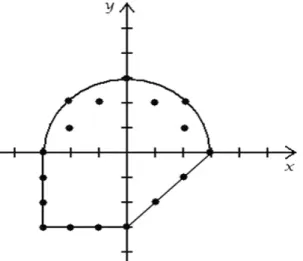
Boundary Value Testing: This criterion consists in choosing the values that are in the
extremes of the domain. Utting refers that boundary testing has some justification because there are lots of faults located at the frontier between two behaviors present in the SUT [UtL06]. This approach is applied to ordered domains whether they are numbers or some user-defined domain since there is some form of ordering the data contained in the domain. In case that we have multiple variables to test together, other decision criteria can be chosen such as:
• All-boundaries coverage that retrieves all possible combination of the variables. Using
the (x, y) variables and their domains of integer values (Figure 3.1) all-boundaries criteria will require all (17) points drawn in the figure. This can become a huge set of values because it tests every point that satisfies the boundary.
• Multidimensional-boundaries coverage requires that each variable has assigned its
maximum and minimum value at least once in the tests. For the example in Figure 3.1 the points (-3,-3), (0, 3) and (3, 0) would suffice.
• All-edges coverage requires that at least one point of each edge is tested. In this case it
only will require two points to satisfy the condition (-3, 0) and (0, -3).
• One-boundary coverage requires only one test and it should be a random point of a
random boundary. We can choose for example the point (2, 2) to cover this criterion.
Statistical data coverage: this method uses a distribution D to select random values to be
tested. With this approach we have to give the distribution of the variable (normal distribution, uniform distribution, among others) and then we can obtain the amount of tests that we desire. For example with boundary value coverage we have a set of tests and we want to add some more. We can implement statistical data coverage to complement test suites generated using previous criteria, giving more values to execute the test suite.
Since choosing the values is done randomly (depending on a distribution that can change the probability of some values being selected) this approach can select data even from unordered domains. In case of specified domains (example of sexes Male or Female) we can weight each possible value giving more or equivalent weight to one of the variables (i.e. Male=45% and Female=55%).
In Pairwise testing, two related variables are tested to verify if the behavior of them working together is the expected. This assumes that in most cases, the faults come when trying
Figure 3.1: Integer boundary points of a complex
domain.
Models, coverage criteria and tools for model-based testing
to combine two variables containing certain values. There are also other approaches that differ from pairwise testing, instead of duets of variables, the use of triplets and quadruples of variables are used. Those are less used because the number of tests would increase significantly.
3.2.3 Fault model criteria
The main goal of software testing is to find errors/faults in the application. Fault based testing is used to test the absence of some common errors. They are generally based on specific models that are used to specify test data.
Appendix A was taken from [KFN99] and shows common GUI errors encountered in several applications.
Fault testing is sometimes supported by mutation testing. Mutation testing tries to solve the problem of not being able to measure the quality of the tests. Mutation testing assumes that we have a test suite and that we have a program that passes the test suite. Then, one minor change in the code is done (creating a mutant program) and the test suite is run against the mutant program. This step is done several times. One of two things can happen to each mutant: the test suite detects the change in the code and the mutant is said killed; it can also happen that the test suite does not find the change in the code and then we have an equivalent mutant or an inadequate test suite.
The ratio of killed mutants gives an idea on how robust to changes is the code and how good our test suite is [Mar06].
3.2.4 Standard testing checklists
The coverage of predefined checklist like the one presented in [Baz09] can also be used as coverage criteria.
Models, coverage criteria and tools for model-based testing
In this checklist the basic steps to test controls in the applications are detailed so testers know what to do without doubt. Figure 3.2 is a portion of the file only for exemplification purposes showing how to test a button on interfaces, showing a lot of possibilities to activate it. It does not say what should be the behavior of the button activations because that is dependent on the application itself. Ways to test other controls can be found in the complete checklist.
3.3 Tools for MBT
There are some tools that actually supports MBT to model and test the systems. Here will be introduced a short list of the tools found.
Spec Explorer [SpE09] is a tool that uses pre/post models to model the system. The model is implemented in a language called Spec# [SpS09]. This language extends C# with contracts (invariants, pre/post conditions, actions, probe actions), value-based collection types and other features. The methods annotated with the “Action” keyword represent the externally callable update to the variables, for testing purposes. These actions can be of two kinds. The first is a probe action and must be annotated with “Action (Kind=ActionAttributeKind.Probe)”. This
kind of action represents queries to the class attributes that can be called for testing purposes. The other kind of action is the Scenario action. This is annotated using “Action (Kind=ActionAttributeKind.Scenario)” and allows the definition of test scenarios. Besides allowing the definition of manual tests, the tool is also able to generate a test suite. But, it cannot generate the tests directly from the pre/post model. To generate the test suite, the tool generates first an FSM and then generates the test suite using transition-based coverage criteria.
An interesting tool to implement MBT is ParTeG [Par08]. This tool is a free plugin for the Eclipse Framework [Ecl09] that allows the creation of UML state machine models visually and then generates a test suite using selected coverage criteria. The tool provides the basic controls to create a complex model. The test suite generated can be executed using JUnit [JUn09]. The tool can also generate mutation tests and, when executed, shows how many of the mutants were killed and how many remain alive, revealing how robust the model is. The tool also includes two examples (elevator control in Figure 3.3 and sorting machine) to better understand how to use it.
Conformiq Qtronic [QTr09] is a commercial MBT tool that uses as input a UML state machine model, complemented with textual specifications in a Java [Jav09] like language named QML. The tool supports several coverage criteria for test generation (transition coverage, boundary value analysis, requirements coverage among others). This tool can also be integrated with Eclipse to generate test suites to the model defined. The model has to be done in Conformiq Modeler tool. This tool also provides traceability matrices between coverage goals (structural features and high-level testing requirements) and test cases. It also provides message sequence charts of the test cases.
Esterel Technologies also commercialize a tool named Model Test Coverage (MTC) that “measures the coverage of the design reached by a high-level requirements-based test suite.
MTC thus verifies if every element of the SCADE model (i.e., every software design feature) has been dynamically activated, and makes it possible to detect unintended functions” [MTC09].
The last framework presented is the GUITAR (GUI Testing frAmewoRk) project.
“GUITAR is a suite of models, components, and tools for automated testing of software applications that have a Graphical User Interface (GUI) front-end” [GUI09]. This framework allow to create test cases from Java and Windows applications detecting software crashes. It also allows to consult the structure of the application, its properties and capture test sessions to execute later.
Models, coverage criteria and tools for model-based testing
3.4 Conclusions
In this chapter were presented different kinds of models to use with MBT. The best models are state-transition models because they have a visual component and can be understand by most of the people. In these models, UML is valued because it is a standard. Pre/post models require more skills to implement and to understand the whole model.
Different coverage criteria can be combined to obtain a better test suite. Control-flow can be used in all kinds of models as well as data coverage and fault-based criteria. Only transition-based criteria are applied to state-transition models. There are also checklists that give the tester all the steps required to test successfully a specified control/element.
Finally, several tools were presented. Some of the tools use pre/post models and other use state-transition models. They all lack model coverage analysis features, although most of them have test generation based on selected criteria.

![Figure 2.2: Manual testing process [UtL06].](https://thumb-eu.123doks.com/thumbv2/123dok_br/15718762.1070219/23.892.328.604.234.690/figure-manual-testing-process-utl.webp)
![Figure 2.3: Manual scripting process [UtL06].](https://thumb-eu.123doks.com/thumbv2/123dok_br/15718762.1070219/24.892.320.603.403.913/figure-manual-scripting-process-utl.webp)
![Figure 2.4: Keyword-driven testing process [UtL06].](https://thumb-eu.123doks.com/thumbv2/123dok_br/15718762.1070219/25.892.322.608.268.712/figure-keyword-driven-testing-process-utl.webp)
![Figure 2.5: Capture/replay process [UtL06].](https://thumb-eu.123doks.com/thumbv2/123dok_br/15718762.1070219/27.892.328.613.218.622/figure-capture-replay-process-utl.webp)
![Figure 2.6: Model-based testing process [UtL06].](https://thumb-eu.123doks.com/thumbv2/123dok_br/15718762.1070219/29.892.322.605.424.826/figure-model-based-testing-process-utl.webp)