Braz. J. of Develop.,Curitiba, v. 6, n. 11, p. 92103-92118, nov. 2020. ISSN 2525-8761
Heat flow avaliation in closing system in light steel framing
Avaliação do fluxo de calor no sistema de fechamento em light steel framing
DOI:10.34117/bjdv6n11-569
Recebimento dos originais: 20/10/2020 Aceitação para publicação: 26/11/2020
Thassiana Armond Muzzi
Civil Engineering PhD student at Escola de Minas – UFOP Universidade Federal de Ouro Preto
Endereço: Campus Morro do Cruzeiro, Bauxita, 35400-000, Ouro Preto, MG, Brasil E-mail: [email protected]
Adriano Pinto Gomes
Professor Ph.D. at IFMG – Campus Ouro Preto Instituto Federal de Minas Gerais
Endereço: Rua Pandiá Calógeras, 898, Bauxita, 3540-000, Ouro Preto, MG, Brasil E-mail: [email protected]
Henor Artur de Souza
Professor Ph.D. at Escola de Minas - UFOP Universidade Federal de Ouro Preto
Endereço: Campus Morro do Cruzeiro, Bauxita, 35400-000, Ouro Preto, MG, Brasil E-mail: [email protected]
ABSTRACT
The use of steel in construction appears as an alternative to change the overview of this sector, contributing to increase productivity, reduce waste and the running time of construction. The Light Steel Framing System (LSF) introduced in Brazil in the late 1990s is going through a process of technical development and acceptance in the domestic construction market, but there are still shortcomings in the design, detailing and implementation of complementary systems of closing and also in its thermal performance. This study covers an analytical approach in which simplified methods of calculating resistance and thermal transmittance and a numerical approach are presented, using the computer program ANSYS (version 15) for checking and comparing of these methods. It is considered the closing of multi-layer compound in the outer layer by cement board and the inner layer of gypsum board, brokered by fiber glass insulation, with studs formed by C-sections profiles in galvanized steel. Among the simplified methods discussed in analytical analysis, the method of Isothermal Plans showed the lowest value of thermal resistance and thus the highest thermal transmittance and heat flow. In relation to the numerical analysis, the results showed that the heat flow is equal to a value around 49% higher than the heat flux value for a closing without the presence of steel profile. The method of Modified Zone showed the smallest difference in the value of the equivalent thermal resistance in comparison of analytical and numerical analysis.
Keywords: Light Steel Framing, thermal resistance, thermal transmittance, Analytical, Numerical simulation.
Braz. J. of Develop.,Curitiba, v. 6, n. 11, p. 92103-92118, nov. 2020. ISSN 2525-8761 RESUMO
O uso do aço na construção civil aparece como uma das alternativas para mudar o panorama desse setor, contribuindo para aumentar a produtividade, diminuir o desperdício e o tempo de execução da construção. O sistema Light Steel Framing (LSF) introduzido no Brasil no final da década de 1990 está passando por um processo de desenvolvimento técnico e de aceitação no mercado da construção civil nacional, mas ainda existem deficiências no projeto, no detalhamento e na execução dos sistemas complementares de fechamento e também no seu desempenho térmico. Esse estudo abrange uma abordagem analítica na qual são apresentados os métodos simplificados de cálculo da resistência e transmitância térmicas e uma abordagem numérica, utilizando o programa computacional ANSYS (versão 15), para a verificação e comparação desses métodos. Considera-se o fechamento em multicamadas composto na camada externa por placa cimentícia e a camada interna por gesso
acartonado, intermediadas por lã de vidro, com montantes formados por perfis Ue em aço galvanizados.
Dentre os métodos simplificados abordados na análise analítica, o método dos Planos Isotérmicos apresentou o menor valor de resistência térmica e desse modo a maior transmitância térmica e fluxo de calor. Em relação à análise numérica, os resultados mostraram que o fluxo de calor equivale a um valor em torno de 49% maior que valor do fluxo de calor para um fechamento sem presença do perfil em aço. O método da Zona Modificada apresentou a menor diferença no valor da resistência térmica equivalente na comparação entre as análises analítica e numérica.
Palavras-Chave: Light Steel Framing, Resistência Térmica, Transmitância térmica, Análise analítica, Simulação numérica.
1 INTRODUCTION
In the face of technological advances, the construction industry in the world has sought more efficient building systems in order to increase productivity, reduce waste and meet the demand of housing deficit. In Brazil, the construction industry is still dominated by conventional masonry and concrete, characterized by low productivity and especially the great waste. However, the domestic market has shown that this situation is changing and that the use of new technologies is the best way to enable industrialization and the rationalization of construction processes. In this respect, the use of LSF building system presents itself as an alternative to change the industry landscape (SANTIAGO; FREITAS; CRASTO, 2012).
The LSF is characterized by galvanized steel cold formed sections, which are a skeletal structure able to withstand the loads required by the construction and by the various components and interrelated subsystems that enable and industrialized construction (SANTIAGO; FREITAS; CRASTO 2012; RODRIGUES; CALDAS, 2016). Galvanized steel profiles are used to form structural or non-structural panels, floor beams, secondary beams, scissors roof and other components.
Structural panels are formed by galvanized profiles of C-section, constituting guides on the top and bottom of the panels; and by C-sections profiles, called "studs", which are regularly spaced 400 or 600 mm from each other according with the modulation defined in structural calculation. The plates
Braz. J. of Develop.,Curitiba, v. 6, n. 11, p. 92103-92118, nov. 2020. ISSN 2525-8761 attached to the structure form the internal or external locks. The other components of the LSF elements are lightweight and compatible with the system concept, which is the formation of a joint with low own weight.
In Brazil, the products available for the closing of buildings in Light Steel Framing are provided on plates or metal sheets with various thicknesses and the most used are the cement board and gypsum board, the latter should only be used in indoor applications. Such closing should be interspersed with thermal insulator layer (fiber glass) and air.
The use of LSF system implies a gain in construction technology, allowing tighter control of processes. Once it is a streamlined system it is suitable for industrial production, contributing to the design of more efficient buildings in many ways, such as sustainable construction due to the possibility of recycling materials and rationalization in the loss of material (CRASTO, 2005; CAMPOS, 2010).
However, there are still shortcomings in the design, detailing and implementation of supplementary closing systems (SANTIAGO; FREITAS; CRASTO, 2012). To improve the performance of LSF system in Brazil is necessary to adjust it to Brazilian culture and climate in order to also meet the viability of costs. Reduce costs and increase the system's efficiency is a concern of all countries that use it.
In the constructions in LSF, the structural elements can lead to problems such as excessive transmission of heat between the external environment and the internal and moisture condensation on the inner surface of the outer closing panels. In LSF system the set of studs of steel profiles correspond to less than 0.5% of the closing area. However, since the thermal conductivity of the steel can be 1500 times higher than that of insulating material, ignoring the analysis of the profile’s thermal performance of buildings in rigid climatic conditions can lead to an overestimation of the thermal resistance of the construction by 50% (GORGOLEWSKI, 2007).
One way of checking the thermal performance of buildings in Light Steel Framing is by calculating the thermal resistance. This check can be made by simplified calculation methods and through numerical simulation. In this work we present a study of simplified methods for calculating the equivalent thermal resistance of locks in Light Steel Framing system and also an assessment through numerical simulation to calculate the heat flow through the closing.
2 METHODS OF THERMAL RESISTANCE EQUIVALENT CALCULATION
There were developed some simplified methods for calculating the equivalent thermal resistance and thermal transmittance for closing in Light Steel Framing. The results of these methods
Braz. J. of Develop.,Curitiba, v. 6, n. 11, p. 92103-92118, nov. 2020. ISSN 2525-8761 are often compared with the results obtained experimentally and, for the most part, exhibit good precision. Both the simplified methods (IISI, 2001) and computer simulation allow an analysis of different projective proposals, contributing as a design tool.
2.1 PARALLEL PATH METHOD
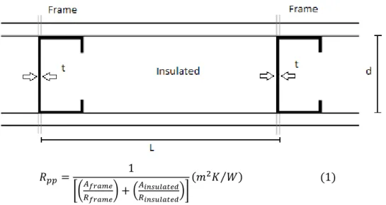
The parallel path method (ASHRAE 2013) assumes a one-dimensional heat flow perpendicular to the face of the element, its means, the heat flow through the thermal bridge is parallel to the heat flow through the insulating and non-heat distribution and there is no side-heat distribution between the structural material and the insulating material (Figure 1). Thus, it is calculated the thermal resistance through the structural elements and the cavity. These resistances are then weighted according to their respective areas in relation to the total area (Eq. 1), depending on the proportion of the structural material in relation to a homogenous layer.
Figure 1 - Method of Parallel Path.
𝑅𝑝𝑝= 1 [(𝐴𝑓𝑟𝑎𝑚𝑒 𝑅𝑓𝑟𝑎𝑚𝑒) + ( 𝐴𝑖𝑛𝑠𝑢𝑙𝑎𝑡𝑒𝑑 𝑅𝑖𝑛𝑠𝑢𝑙𝑎𝑡𝑒𝑑)] (𝑚2𝐾 𝑊⁄ ) (1)
Where Rframe is the thermal resistance calculated through the structural steel (m2K/W), Rinsulated
is the thermal resistance calculated from the insulating material assembly (m2K/W), Aframe is the
fraction of the area of the structure 𝑡
𝐿 e Ainsuladet is the fraction of the area of the insulating
material(1 −𝑡
𝐿).
2.2 METHOD OF ISOTHERMAL PLANS
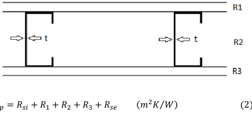
The method of isothermal planes (ASHRAE 2013) assumes that the temperature is uniform in each parallel plane of the face of the element, ie, the heat flux through the closing is completely
Braz. J. of Develop.,Curitiba, v. 6, n. 11, p. 92103-92118, nov. 2020. ISSN 2525-8761 redistributed at each layer (isothermal planes) and there is no resistance to the lateral heat flow, its means, one-dimensional heat flow. Figure 2 shows the variables that must be considered in the method of isothermal planes, while in equation 2 shows the form of the resistance calculation.
Figure 2 - Method of Isothermal Plans
𝑅𝑖𝑝= 𝑅𝑠𝑖+ 𝑅1+ 𝑅2+ 𝑅3+ 𝑅𝑠𝑒 (𝑚2𝐾 𝑊⁄ ) (2)
Where R1 is the thermal resistance of the layer (m2K/W) 1 and R2 is the resistance of the layer
2 (m2K/W), and is calculated by Equation 3.
𝑅𝑡ℎ𝑟𝑜𝑢𝑔ℎ𝑡 𝑏𝑟𝑖𝑑𝑔𝑒𝑑 𝑙𝑎𝑦𝑒𝑟= 1 [(𝐴𝑓𝑟𝑎𝑚𝑒 𝑅𝑠𝑡𝑒𝑒𝑙 ) + ( 𝐴𝑖𝑛𝑠𝑢𝑙𝑎𝑡𝑖𝑜𝑛 𝑅𝑖𝑛𝑠𝑢𝑙𝑎𝑡𝑖𝑜𝑛)] (𝑚2𝐾 𝑊⁄ ) (3)
Where R3 is the thermal resistance of layer 3 (m2K/W) and Rsi and Rse are the internal and
external surface thermal resistance (m2K/W).
2.3 AVERAGE OF METHODS OF PARALLEL PATH AND ISOTHERMAL PLANS
The norm EN ISO 6946 (ISO 2007) introduces a method for calculating the thermal resistance and thermal transmittance of building elements using an average of the parallel path method and the method of temperature-controlled Plans (50/50 rule). Thus, the total thermal resistance was calculated by Equation 4.
𝑅𝒕 =
𝑅𝒑𝒑+ 𝑅𝒊𝒑
2 (𝑚
2𝐾 𝑊⁄ ) (4)
Where Rpp is the total thermal resistance of the element by using the method of the parallel path
(m2K/W), and Rip is the total thermal resistance of the element by using the method of Isothermal Plans
Braz. J. of Develop.,Curitiba, v. 6, n. 11, p. 92103-92118, nov. 2020. ISSN 2525-8761 2.4 DANISH STANDARD DS418
When using a combination of methods of Isothermal Plans and Parallel Path, as suggested in EN ISO 6946 (ISO 2007), you can adjust coefficients to fit the empirical data. It has been found that the 1:1 ratio represents the best coefficients of wooden structures and masonry construction. However, a 2:1 ratio of the coefficients (isothermal plane: parallel path) has been suggested for several test data to better represent the performance of light steel framing systems. Thus, the total thermal resistance was calculated by Equation 5.
𝑅𝒕 =𝑅𝒑𝒑+ 2. 𝑅𝒊𝒑
3 (𝑚
2𝐾 𝑊⁄ ) (5)
2.5 CANADIAN CODE METHOD ENERGY
The Canadian Energy Code (NRC, 1997) proposes a combination between Parallel Path Method of Isothermal Plans and the Isothermal Plan Method. The ratio of the values of the resistors was determined empirically using hot box protected test data. The analysis of this test suggested that the proportion would vary depending on the configuration of the building. So it was found that results more accurate were obtained when coefficients varied depending on the details of construction. The final proposal is presented in Equation 6.
𝑅𝒕 = (𝐾1. 𝑅𝑝𝑝) + (𝐾2. 𝑅𝑖𝑝) (𝑚2𝐾 𝑊⁄ ) (6)
Where Rpp is the total thermal resistance of the element by using the method of the parallel path
(m2K/W) and Rip is the total thermal resistance of the element by using the method of Isothermal Plans
(m2K/W). The constants K1 and K2 are shown in Table 1.
Table 1- Weighting factors used in Canadian Code Method Energy
Source: adapted from IISI (2001).
2.6 THE MODIFIED ISOTHERMAL PLANS METHOD
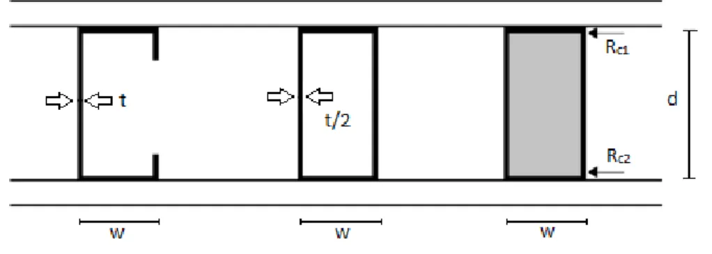
The calculation method proposed is a one-dimensional modification of the method of isothermal plans developed by the Research Association of New Zealand Building (BRANZ, 1998). In this calculation method, the metal section is replaced by an ideal rectangle with the same overall width and depth profile (Figure 3). However, the thermal conductivity is used to calculate the steel
Frame Spacing K1 K2
< 500 mm without insulating sheating 1/3 2/3
< 500 mm with insulated sheeting 2/5 3/5
Braz. J. of Develop.,Curitiba, v. 6, n. 11, p. 92103-92118, nov. 2020. ISSN 2525-8761 conductivity multiplied by the ratio of stud thickness multiplied by the width of the table. The justification for this is that the thermal conductivity of steel is so high that even a thin cross section offers little resistance in heat transfer.
Figure 3 - Profiles Transformation C-shaped or box-shaped stud into a notional equivalent solid rectangle.
In the method of the modified isothermal planes it is taken into account the thermal contact resistance between the table and the closing profiles materials using to calculate a typical value of 0,035
m2K/W suggested by ASHARE (2013). Thus, to calculate the thermal resistance through structural
steel components, the BRANZ method (1998) adds the Rc1and Rc2 contact resistances in the thermal
resistance of the steel, as follows:
𝑅𝑎ç𝑜= [( 𝑑 𝐾) . ( 𝑊 𝑡)] + 𝑅𝑐1+ 𝑅𝑐2 (𝑚 2𝐾 𝑊⁄ ) (7)
Where “d” is the dimension of the profile core (m); “k” is the thermal conductivity of steel (W/m.K); w is the width of the profile table (m); t is the thickness of the profile (m), and Rc1 and Rc2
are the thermal contact resistance (m2K/W).
2.7 MODIFIED ZONE METHOD
The Modified Zone Method (MZM) is based on the parallel path method and Zone Method (ASHRAE 2013). The only difference between the three methods is the manner in which the area of the closing affected by the thermal bridge is taken into consideration. The parallel path method assumes that the area affected by the thermal bridge is only the actual geometric area profile.
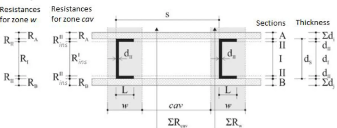
According to the Modified Zone Method, the cross section of the panel is divided into two zones: the zone of thermal anomalies around the profiles (w) and the area of the cavity (cav). The panel components are grouped in sections A: external closing; B: Internal and closing sections I and II: Insulating and profile (Figure 4) (GOMES, 2012).
Braz. J. of Develop.,Curitiba, v. 6, n. 11, p. 92103-92118, nov. 2020. ISSN 2525-8761
Figure 4 - Parameters for the calculation of thermal resistance in the MZM method.
Source: adapted from ASHRAE, 1997 (GOMES, 2012).
In order that the Zone Method (ASHRAE, 2009) presents more accurate results, the laboratory Oak Ridge National Laboratory (ORNL, 1943) and the National Association of Home Builders of the United States (National Association of House Builders, NAHB, 1940) introduced the zone factor (Zf) to adjust the zone of influence of the profile. The use of the zone factor increases the accuracy of the zone method of + 15 % to 2% (AISI, 1995). The width of the zone of thermal anomalies (w) can be obtained by the equation 9.
Assuming that the layer or layers of the section is thicker than the section B, as shown in Figure 4, thus: ∑ 𝑑𝑖 𝑛 𝑖=1 ≥ ∑ 𝑑𝑗 𝑚 𝑗=1 (8)
Where n is the thickness of the section (m); m is the section thickness B (m).
Then, the width of the thermal zone around the metallic section (w) can be estimated by:
𝑤 = 𝐿 + 𝑍𝑓∑ 𝑑𝑖 𝑛
𝑖=1
(9)
Where L is stud flange size; di is the thickness of material layer in section A; Zf is the zone
factor, (Zf = 2 to the zone method); Zf is equal to -0,5 (se ∑𝑑𝑖𝑒 ∑ 𝑑𝑗 ≤ 16𝑚𝑚 and closing resistivity
≤ 10,4 m.K/W); Zf is equal to 0,5 (se ∑𝑑𝑖𝑒 ∑ 𝑑𝑗 ≤ 16𝑚𝑚 and closing resistivity ˃ 10,4 m.K/W).
Braz. J. of Develop.,Curitiba, v. 6, n. 11, p. 92103-92118, nov. 2020. ISSN 2525-8761
Figure 5 - Chart from Zf zone factor.
Source: adapted from ASHRAE, 2013
The total thermal resistance (surface to surface) can be determined by equation 10.
𝑅𝑡 =
∑ 𝑅𝑤. ∑ 𝑅𝑐𝑎𝑣. 𝑆
𝑤. (∑ 𝑅𝑐𝑎𝑣− ∑ 𝑅𝑤) + 𝑆. ∑ 𝑅𝑊
(10)
Where Rt is the total thermal resistance (of the surface area) (m².K/W); s is the distance between the studs (m); w is the width of the profile influence zone (m); ∑ 𝑅𝑤 = 𝑅𝐴+ 𝑅𝐵+ 𝑅𝐼+ 2𝑅𝐼𝐼 (11) ∑ 𝑅𝑐𝑎𝑣 = 𝑅𝐴+ 𝑅𝐵+ 𝑅𝑖𝑛𝑠𝐼 + 2𝑅𝑖𝑛𝑠 𝐼𝐼 (12) 𝑅𝐴= ∑(𝑟𝑖. 𝑑𝑖) (13) 𝑅𝐵= ∑(𝑟𝑗. 𝑑𝑗) (14) 𝑅𝑖𝑛𝑠𝐼 = 𝑟𝑖𝑛𝑠. 𝑑𝐼 (15) 𝑅𝑖𝑛𝑠𝐼𝐼 = 𝑟𝑖𝑛𝑠. 𝑑𝐼𝐼 (16) 𝑅𝑚𝑒𝑡𝐼 = 𝑟𝑚𝑒𝑡. 𝑑𝐼 (17) 𝑅𝑚𝑒𝑡𝐼𝐼 = 𝑟𝑚𝑒𝑡. 𝑑𝐼𝐼 (18) 𝑅𝐼 = 𝑅𝑚𝑒𝑡𝐼 . 𝑅𝑖𝑛𝑠𝐼 . 𝑤 𝑑𝐼𝐼. (𝑅𝑖𝑛𝑠𝐼 − 𝑅𝑚𝑒𝑡𝐼 ) + 𝑤. 𝑅𝑚𝑒𝑡𝐼 (19) 𝑅𝐼𝐼 = 𝑅𝑚𝑒𝑡𝐼𝐼 . 𝑅𝑖𝑛𝑠𝐼𝐼 . 𝑤 𝐿. (𝑅𝑖𝑛𝑠𝐼𝐼 − 𝑅𝑚𝑒𝑡𝐼𝐼 ) + 𝑤. 𝑅𝑚𝑒𝑡𝐼𝐼 (20)
Braz. J. of Develop.,Curitiba, v. 6, n. 11, p. 92103-92118, nov. 2020. ISSN 2525-8761
Where RA is the thermal resistance of the section A (m2.K/W); RB is the thermal resistance of
the section B (m2.K/W); RI is the thermal resistance of the section I (m2.K/W); RII is the thermal
resistance of the section II (m2.K/W); RIins is the thermal resistance of the section RIins (m2.K/W); RIIins
is the thermal resistance of the section RIIins (m2.K/W); RIins is the thermal resistance of the section RIins
(m2.K/W); RImet is the thermal resistance of the section RImet (m2.K/W); RIImet is the thermal resistance
of the section RIImet (m2.K/W).
3 METHODOLOGY
Two approaches are adopted to obtain the equivalent thermal resistance and thermal transmittance for closing in Light Steel Framing: the analytical analysis and numerical analysis. In both
cases it was used a closing, whose area is limited to 0.045m2 for configuring the simulation cell which
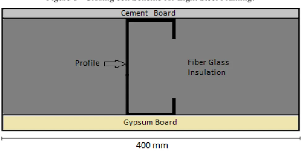
is modulated according to the LSF building system where the sums are spaced at 400mm , as illustrated in Figure 6.
Figure 6 - Closing cell Scheme for Light Steel Framing.
The closing composition used in the outer layer is composed of cement board of 10 mm thick and the inner layer of gypsum board with a thickness of 12.5 mm, intermediated by fiber glass insulation and C-sections profile amount (90x40) in galvanized steel, with a thickness of 0.95mm.
3.1 ANALYTICAL ANALYSIS
The analytical analysis is based on calculations of thermal resistance closing methods for Light Steel Framing system (IISI, 2001), as presented above.
Braz. J. of Develop.,Curitiba, v. 6, n. 11, p. 92103-92118, nov. 2020. ISSN 2525-8761 3.2 NUMERICAL ANALYSIS
Numerical analysis is based on the Finite Element Method (FEM) using ANSYS software. The Finite Element Method (FEM) is based on the closing of the discretization elements, thereby generating a mesh of elements and nodes. By means of appropriate interpolation functions, this discrete system simulates the original continuous system behavior. The advantage of the finite element method is the range of possibilities of use, since the finite elements adapt to the geometry element (ANSYS, 2013).
ANSYS has a different library of elements according to the type of analysis required. For this thermal analysis was used PLANE55 element, which is an element whose characteristic is the temperature at four nodes with a single degree of freedom. This element is effective for thermal analysis, 2-D, both for transient and for permanent state condition.
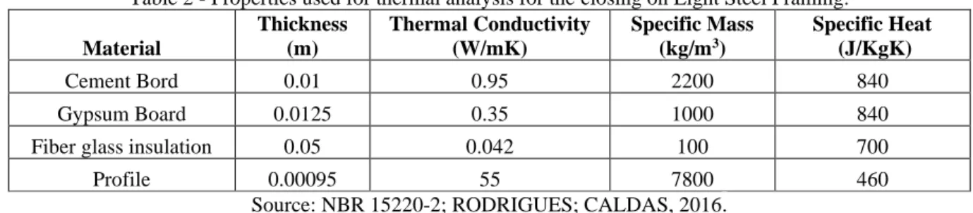
For thermal analysis, plus the thickness of three thermo physical properties were inserted in the program to obtain the required result. These properties are shown in Table 2.
Table 2 - Properties used for thermal analysis for the closing on Light Steel Framing. Material Thickness (m) Thermal Conductivity (W/mK) Specific Mass (kg/m3) Specific Heat (J/KgK) Cement Bord 0.01 0.95 2200 840 Gypsum Board 0.0125 0.35 1000 840
Fiber glass insulation 0.05 0.042 100 700
Profile 0.00095 55 7800 460
Source: NBR 15220-2; RODRIGUES; CALDAS, 2016.
The mesh refinement was related according to the thickness of the steel profile, 0,95mm. Refinement levels were tested, seeking a better refinement of the mesh in C-sections profile area. The tests, revealed an element with approximately 32 % of the thickness profile. For other areas, the mesh
refinement was approximately 4% in relation to the closing area of 0,045m2.
4 RESULTS
4.1 RESULTS FROM THE ANALYTICAL ANALYSIS
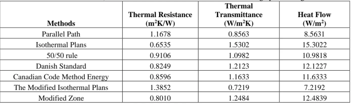
The calculations are performed for all the methods presented above for the closing shown in Figure 6. In table 3 there are the results of equivalent thermal resistance, thermal transmittance and heat flow calculations, whereas a shallow gradient of 10ºC temperature, which represents a typical thermal behavior of an applied closing in the tropical climate buildings in Brazil.
Braz. J. of Develop.,Curitiba, v. 6, n. 11, p. 92103-92118, nov. 2020. ISSN 2525-8761
Table 3 - Thermal resistance, transmittance and heat flow to the mediated closing by insulating material.
Methods Thermal Resistance (m2K/W) Thermal Transmittance (W/m2K) Heat Flow (W/m2) Parallel Path 1.1678 0.8563 8.5631 Isothermal Plans 0.6535 1.5302 15.3022 50/50 rule 0.9106 1.0982 10.9818 Danish Standard 0.8249 1.2123 12.1227
Canadian Code Method Energy 0.8596 1.1633 11.6333
The Modified Isothermal Plans 1.3852 0.7219 7.2192
Modified Zone 0.8010 1.2484 12.4839
It can be verified that the analytical solution by Isothermal Plans method has the lowest value of thermal resistance and thus the highest thermal transmittance and heat flow and the Danish Standard methods, Canadian Code of Energy and modified zone have very close results between itself.
4.2 RESULTS FROM THE NUMERICAL ANALYSIS
It is made a thermal analysis in permanent regime, one-dimensional heat conduction, whereas considering the known surface temperature and applying to the closing a temperature gradient of 10ºC, which represents a typical thermal behavior of a closing applied in tropical constructions in Brazil.
Figure 7 shows the stratification of temperature for the closing that has insulating material as an intermediate layer.
Figure 7 - Stratification of the temperature for closing
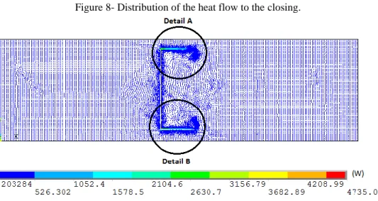
It can be seen in the data shown in Figure 7 that there is a difference in temperature distribution in the profile region of steel, in relation to the distal region of the element, its means, there is a region in which the conduction heat flux is two-dimensional rather than one-dimensional (figure 8 to 10). The heat flux in this region results, in this case, is about 9 times higher than the wall flux conduction without the presence of steel profile.
Braz. J. of Develop.,Curitiba, v. 6, n. 11, p. 92103-92118, nov. 2020. ISSN 2525-8761
In this case the equivalent thermal resistance resulted in Rt = 0.7673m2K/W and the heat flow
in 13.0332W/m2. This heat flow is equivalent to a value around 49 % higher than the heat flux value
for a closing without the presence of steel profile.
Figure 8- Distribution of the heat flow to the closing.
Figure 9 - Distribution of heat flow to the lock - detail A.
Detail C – stiffener
Figure 10 - Heat flux distribution to the lock- - detail B.
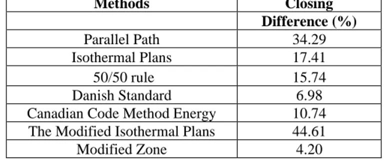
Braz. J. of Develop.,Curitiba, v. 6, n. 11, p. 92103-92118, nov. 2020. ISSN 2525-8761 When comparing the value of the equivalent resistance obtained by numerical simulation with the strength values obtained from the analytical analyzes it is observed that the results in a modified zone method results in a closest value, providing a difference in about 4.20% (Table 4).
Table 4 - Difference in equivalent thermal resistance value, analytical analysis versus numerical analysis.
Methods Closing Difference (%) Parallel Path 34.29 Isothermal Plans 17.41 50/50 rule 15.74 Danish Standard 6.98
Canadian Code Method Energy 10.74 The Modified Isothermal Plans 44.61
Modified Zone 4.20
5 CONCLUSIONS
The studied closing cell, where the cavity is completely filled with thermal insulator, the Isothermal Plans method was the one that presented the result with the lowest value of the equivalent
thermal resistance (0.6535m2K/W) compared to other methods. Thus, this method has a greater heat
transfer coefficient and hence the greatest heat flow.
Comparing the value of the equivalent resistance obtained by numerical simulation
(0.7673m2K/W) with the value obtained by analytical analysis, it is observed that the method of the
modified zone, recommended by ASHRAE standards, shows the best result providing a maximum difference around 4.20%.
ACKNOWLEDGMENTS
Braz. J. of Develop.,Curitiba, v. 6, n. 11, p. 92103-92118, nov. 2020. ISSN 2525-8761 REFERENCES
AMERICAN IRON AND STEEL INSTITUTE (AISI). Thermal design guide for exterior walls. Washington: American Iron and Steel Institute, 1995. (Technical data).
AMERICAN SOCIETY OF HEATING, REFRIGERATING AND AIR CONDITIONIG ENGINEERS (ASHRAE). ASHRAE Handbook: Fundamentals. Atlanta, ASHRAE, 2013.
ANSYS. User`s Manual for Revision 15. 2013, Swanson Analysis Systems Inc. Inc., Houston, PA. ASSOCIAÇÃO BRASILEIRA DE NORMAS TÉCNICAS (ABNT). NBR 15220: Desempenho térmico de edificações. Rio de Janeiro, 2005. (in portuguese)
ASSOCIAÇÃO DE PESQUISA DA CONSTRUÇÃO DA NOVA ZELÂNDIA (BRANZ, 1998). Disponível em:<http://www.branz.co.nz/cms_display.php>Acesso em: 03 nov. 2014. (in portuguese) CAMPOS, H. C. Avaliação pós-ocupação de edificações construídas no sistema Light Steel Framing. 2010. 164 f. Dissertação (Mestrado em Engenharia Civil) –PPGDEC, Universidade Federal de Ouro Preto, Ouro Preto, 2010. (in portuguese)
CRASTO, R. C. M. Arquitetura e tecnologia em sistemas construtivos industrializados: light steel framing. 2005. 231 f. Dissertação (Mestrado em Engenharia Civil) – Escola de Minas, Universidade Federal de Ouro Preto, Ouro Preto, 2005. (in portuguese)
DANSK STANDARD. DS 418: Beregninger af Bygningers Varmetab, 2010. 123p.
INTERNATIONAL ORGANIZATION FOR STANDARDIZATION. ISO 6946: Building components and building elements – Thermal resistance and thermal transmittance – Calculation method. British Standards Institution, London, 2007.
GOMES, A. P. Método de Avaliação do Desempenho Térmico de Edifícios Comerciais e Residenciais em Light Steel Framing. 2012. 147 f. Tese (Doutorado em Engenharia Civil) – Escola de Minas, Universidade Federal de Ouro Preto, Ouro Preto, 2012. (in portuguese)
GORGOLEWSKI, M. Developing a simplified method of calculating U-valuesin light steel framing. Building and Environment, 2007. v. 42 p. 230–236.
INTERNATIONAL IRON AND STEEL INSTITUTE (IISI). Thermal performance of Light Steel Frame Housing. Brussels: International Iron and Steel Institute, 2001.
MODEL NATIONAL ENERGY CODE OF CANADA FOR BUILDINGS. NRC National Research Council of Canada, Ottawa, 1997.
NAHB - ASSOCIATION OF HOUSE BUILDERS. 1940. Disponível
em:<http://www.nahb.org/default.aspx>. Acesso em: 03 nov. 2014. (in portuguese)
ORNL - OAK RIDGE NATIONAL LABORATORY. Advanced Wall Systems. 1943. Disponível em: <http://web.ornl.gov/sci/roofs+walls/AWT/Ref/Home.htm>. Acesso em: 10 ago. 2014. (in portuguese)
Braz. J. of Develop.,Curitiba, v. 6, n. 11, p. 92103-92118, nov. 2020. ISSN 2525-8761 RODRIGUES, F. C.; CALDAS R. B. Steel Framing: Engenharia. Rio de Janeiro: IBS/CBCA, 2016. (Série Manual de Construção em Aço. (in portuguese)
SANTIAGO, A. K.; FREITAS, A. M. S.; CRASTO, R. C. M. Steel Framing: Arquitetura. Rio de Janeiro: IBS/CBCA, 2012. (Série Manual de Construção em Aço). (in portuguese)