of Chemical
Engineering
www.scielo.br/bjcePrinted in BrazilVol. 35, No. 01, pp. 51 – 61, January – March, 2018
*Corresponding author: Ígor Renz Cadore. E-mail: [email protected]; Phone: +55 51 3308 5485; Cell Phone: +55 51 9666 8123. dx.doi.org/10.1590/0104-6632.20180351s20160416
WASTEWATER TREATMENT IN A PILOT-SCALE
SUBMERGED MEMBRANE BIOREACTOR: STUDY
OF HYDRODYNAMICS UNDER CONSTANT
OPERATING PRESSURE
Ígor Renz Cadore
1,*, Maurício Kipper da Silva
1
,
Liliane Damaris Pollo
1
and Isabel Cristina Tessaro
1
1 Universidade Federal do Rio Grande do Sul (UFRGS) - Department fo Chemical Engineering, Rua Engenheiro Luiz Englert, Porto Alegre, Brazil, Zip Code 90040040
(Submitted: July 5, 2016; Revised: September 19, 2016; Accepted: November 8, 2016)
Abstract – A pilot-scale Submerged Membrane Bioreactor provided with PEI hollow fiber membranes was operated under constant pressure mode in order to evaluate the effects of hydrodynamic conditions on the process performance, such as air flow rate, module packing density and aeration configuration. For the three different air flow rates studied (2, 5 and 8 L/min), results showed a limit value for this parameter, in which above this value a better performance will not be obtained and can even be worse. The air flow rate of 5 L/min presented the best performance, followed by 8 and 2 L/min. The module packing density was studied for two diameters (0.75 and 1 inch); the best result was observed for the larger diameter module, because lower packing density causes more space between fibers, increasing the aeration homogeneity inside de fiber bundle. Both aeration geometric tested showed similar permeate fluxes, indicating they did not affect the process performance. For all hydrodynamic conditions, the removal of TOC and COD was 96% and 93%, respectively.
Keywords: Submerged Membrane Bioreactor (SMBR), Aeration, Packing Density, Constant Pressure, Hollow Fiber.
INTRODUCTION
To preserve natural water resources, water reuse or water recycling processes have been widely encouraged. A Submerged Membrane Bioreactor (SMBR) has been a good alternative for wastewater treatment process, because it is a combination between the activated sludge biological process and membrane separation technology. In this process, the separation is performed by membrane filtration rather than sedimentation, as in conventional processes, resulting in a high quality effluent. SMBRs further offer advantages such as low sludge production and modular design. However, for constant pressure processes, the fouling formation on the membrane surface causes a
permeate flux decline, making the fouling phenomenon a major concern in SMBR operation.
I.R. Cadore, M.K. da Silva, L.D. Pollo and I.C. Tessaro 52
membrane surface (Braak et al., 2011). For this reason, the aeration flow rate is the main parameter for fouling control and, consequently, to achieve a sustainable permeate flux.
Some studies (Ueda et al., 1997; Chua et al., 2002; Delgado et al., 2008, Fu et al., 2012) have demonstrated a decline in fouling tendency related to increasing air flow rate, but they also reveal a threshold value to improve performance. Above this value, poor effects can occur, as observed by Meng et al. (2008), where the intense aeration caused a floc breakage and, consequently, colloidal and soluble particle release and then a fouling increase. At high aeration flow rates, the particles tend to be smaller, enhancing the probability of fouling formation in the membrane pores due to high concentrations of colloidal and soluble particles (Wu et al., 2012).
In a broader sense, hydrodynamics in SMBR plays an important role in process operation; therefore, the ratio of membrane filtration area (m²) and volume of the membrane module (m³) is relevant for performance of the filtration system. This ratio is named the module packing density. According to Yeo and Fane (2005), there is an expressive improvement with packing density decrease, leading them to conclude that, for higher packing densities, some fibers can get stuck together as their cake layers merge, and then foul rapidly. Lebegue et al. (2008) observed the appearance of dead zones in the center of hollow fiber bundles, depending on the bundle diameter and packing density. Thus a compromise must be found regarding packing density between a sufficient space between fibers (low packing density) and a large membrane area of filtration (high packing density). The same work emphasizes the hydrodynamics homogeneity and this may depends on good design of the aeration system.
Therefore, two hydrodynamics aspects can be pointed: air flow rate and module packing density. In the studies mentioned previously, those aspects were not assessed for the same system. Ueda et al. (1997) and Chua et al. (2002) checked the air flow rate effect on the pressure behavior for a constant flux operation, and they reported that there was a threshold value of aeration that does not affect the pressure driven force to maintain the permeate flux. Delgado
et al. (2008) made a relationship with fouling rate and
shear force intensity, which is responsible for membrane scouring and related to air sparging, and the results showed a strong impact on the cake removal effectiveness with a high shear force. However the shear force reached a limit where fouling cannot be reduced by a shear intensity increase. For those researches, all the experiments were performed for constant flux operation and no relationship with module packing density was carried out.
Thus, to inspect for the same system the aeration rate and packing density behavior, this work intends to evaluate the hydrodynamics effects on process performance. The objective is to study the influence of air flow rate, fiber bundle packing density and aeration geometry on permeate
flux for a submerged membrane bioreactor system under constant pressure operation.
MATERIALS AND METHODS SMBR system
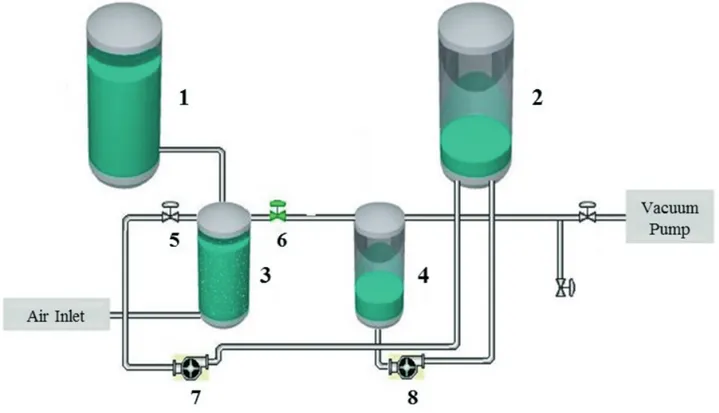
The SMBR system was developed to operate long period experiments and online data collection. Figure 1 presents a system flowchart. The unit operated automatically and under constant pressure, alternating the backwashing/ permeation cycles previously set. Permeate stream was obtained by vacuum application on only one side of the membrane module, then transported to tank 4 equipped with a load charge cell to obtain mass measurements over time and, consequently, process flow rate. The maximum measurement error for this load charge cell was 12%. The process temperature was monitored for permeate flux correction via Equation 1 (Jiang et al., 2005):
(1)
in which J is the process permeate flux (L/m2/h or LMH)
at temperature T (ºC), T is the activated sludge average temperature and J20 is the process permeate flux (L/m2/h) at
the temperature of 20 ºC.
The bioreactor volume was about 8 L (tank 3) and its level was controlled by a level switch linked with a solenoid valve installed at the bottom of the influent tank (tank 1). The aeration system was constructed with porous cylindrical stones of 10.5 mm diameter and 3.2 cm length and it was placed at the bottom of the bioreactor. The air supply was made by an air compressor and air flow rate was controlled by a rotameter in a range of 0 to 10 L/min, providing a DO concentration in the range of 6 – 8 mg/L. The absolute operating pressure adopted for experiments was 400 mbar according to a critical flux test. The permeation/backwashing cycle selected was 15 min / 10 s. The backwash system was turned-on by closing the valve 6, opening valve 5 and activating pump 7 that pumps the permeate inside the membrane module in the opposite direction of filtration.
Two different aeration geometries were used, namely, Mode 1 and Mode 2. The Mode 1 aeration consisted of feeding compressed air only at the bottom of bioreactor by the aeration system. In the Mode 2 aeration, the compressed air was fed at the bottom of bioreactor and also inside the membrane module by fiber aerators constructed with the same PEI hollow fiber membranes used for permeation.
Membranes and Characterization Methods
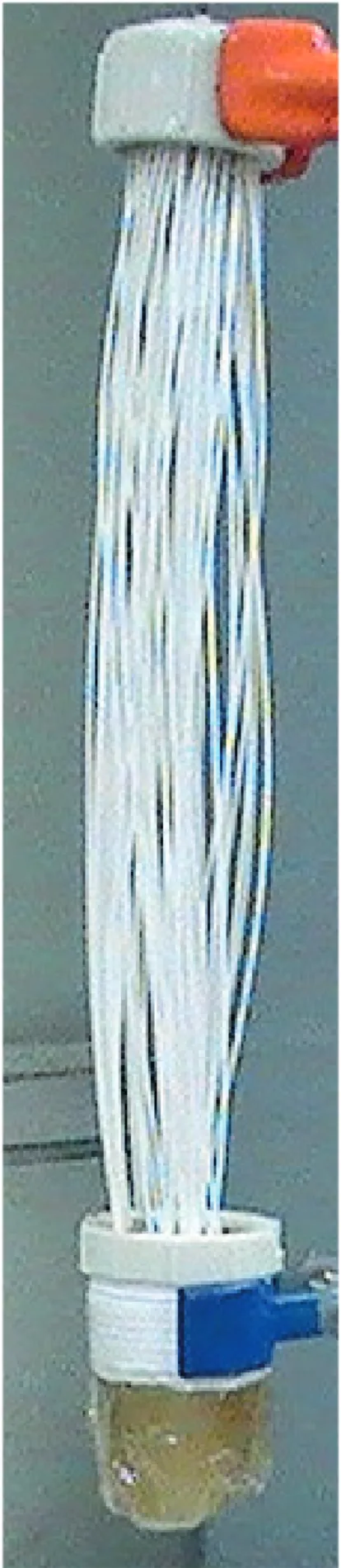
The membrane modules were handmade, constructed with poly(ether)imide (PEI) hollow fi bers in a vertical arrangement (Figure 2). The hollow fi ber external diameter is between 0.8 and 1 mm. The modules were constructed with the same method used by Viero et. al. (2007),
in which both extremities were built with PVC pipe connections and epoxy resin, the bottom extremity was sealed and the top one was left open for permeate suction. About 50 to 60 fi bers were used for each membrane module, with an individual fi ber length between 24 and 28 cm, resulting in a mean permeation area of 0.041 m2.
The module diameter is determined by the PVC connection size, so the two diff erent module diameters tested were 1.91 cm (3/4 in) and 2.54 cm (1 in), corresponding to a module packing density of 543 and 307 m2/m3, respectively.
The membrane morphology was analyzed by scanning electron microscopy (SEM) in a JSM 6060 microscope. Hydraulic permeability, Lp (L/m2/h/bar) was determined
by water permeate fl ux measurements Jp (L/m2/h) due
to applied transmembrane pressure ΔP (bar) , in a range between 650 and 200 mbar, with a 50 mbar step; then values were fi tted to Equation 2:
(2)
Before the hydraulic permeability determination,
it was verifi ed if the membrane structure experienced compaction, a phenomena that consists in a membrane structural densifi cation with an applied transmembrane pressure. The absolute pressure for compaction was 300 mbar until constant water permeate fl ux was reached.
Experimental Procedure
In order to determine the pressure operation, a critical fl ux test was performed with the same methodology used in hydraulic permeability determination, but with activated sludge and not only with distilled water. The permeate fl ux was monitored for 3 hours, in the absolute pressure conditions of 350, 400 and 450 mbar. The permeate fl ux with activated sludge was compared with water permeate fl ux for the same pressure condition, because if this ratio deviates from 1, the critical fl ux pressure was achieved. The air fl ow rate in this test was 2 L/min.
After membrane conditioning and characterization, activated sludge experiments were performed in order to study the eff ects of air fl ow aeration, module packing density and aeration geometry on the system performance. Three air fl ow rates were studied, 2, 5 and 8 L/min; for packing density, diff erent values were obtained with module diameters of 1.91 cm (3/4 in) and 2.54 cm (1 in); Mode 1 and Mode 2 aeration were conducted and compared for the same air fl ow rate. For each condition, a 4-day experiment was performed and the permeate stream was Figure 1. Submerged Membrane Bioreactor system scheme. 1 – Infl uent tank; 2 – Permeate storage tank; 3 – Membrane Bioreactor; 4 –
I.R. Cadore, M.K. da Silva, L.D. Pollo and I.C. Tessaro 54
sampled in an interval of 24 hours to determine organic matter concentration. At the end of operation, permeate flux decline data was obtained and expressed in terms of normalized flux, which is the ratio between experimental permeate flux and initial permeate flux.
Activated Sludge and Feed Solution
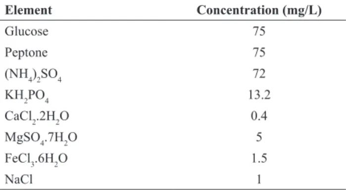
Activated sludge was sampled weekly from a municipal wastewater treatment company, DMAE (Porto Alegre/ Rio Grande do Sul/Brazil), with a sludge retention time of about 10 to 15 days. The stipulated volatile suspended solids (VSS) concentration was 8,000 mg/L. The influent consisted of a glucose-peptone synthetic wastewater, based on the study of Sui et al. (2008), for which the composition is presented in Table 1. According to preliminary tests and to simulate a primary effluent treatment, the synthetic wastewater was prepared with COD in the range of 130 – 160 mg/L and final solution pH was adjusted with sodium hydroxide (NaOH) to 7 (Yue et al., 2015).
Analytical methods
The organic matter removals of the treatment were obtained by COD and TOC measurements of influent and permeate samples. COD was measured according to the Standard Methods colorimetric method (Apha, Awwa, Wef, 1998) and TOC determination was performed in a TOC analyser (Shimadzu, model VCSH). TSS and VSS were also determined according to Standart Methods (Apha, Awwa, Wef, 1998) procedures.
RESULTS AND DISCUSSION Membrane characterization
Figure 3 presents the membrane external surface micrograph. It was possible to detect the membrane pores of selective layers and the illustration also reveals a high superficial porosity of the membrane, so the black regions indicate the presence of active pores that contribute to permeate flux. The cross section micrograph is presented in Figure 4. It was observed that the membrane had a porous and asymmetric internal structure, and the fiber outer side exhibited a selective layer with smaller pores than the fiber inner side.
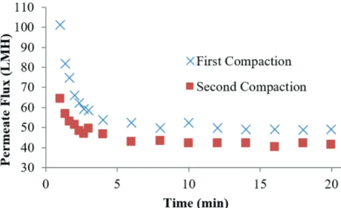
The PEI membrane proved to be compactable, as can be seen by Figure 5. The compaction was performed for new module membranes, until constant distillate water permeate flux was reached, approximately in about 6 minutes for 300 mbar absolute pressure condition. The second compaction was conducted one day after the first one and a slight decompression could be observed. The final permeate flux for the first and second compactions were 49 and 41 LMH, respectively.
Figure 3. SEM image of the PEI membrane surface (x1,000). The results of water hydraulic permeability are shown in Figure 6. The direct linear relationship between pressure operation and permeate flux can be observed. This graphic shows the water permeation test for two different clean membrane modules with the same permeation area, but different hydraulic permeabilities, before they were used in the activated sludge process. After wastewater treatment, the membrane modules presented similar behavior regarding the linear relationship.
Critical flux test
The pressure condition for the activated sludge experiments were obtained previously by a critical flux test. The results are presented in Figure 7. The normalized permeate flux is the ratio of activated sludge permeate flux and water permeate flux for the same pressure.
It was observed that the critical flux pressure condition was near 400 mbar, even if sludge permeate flux values were slightly lower than water permeate flux values (about 94%), they remained almost constant along the 200 min monitoring time. This behavior is consistent with the weak form of critical flux defined by Field et al. (1995), where the sub-critical flux is the flux rapidly established
and maintained during start-up of filtration, but does not necessarily equate to the pure water flux. In the strong form of critical flux definition, the flux obtained during sub-critical operation is equated to the pure water flux, such as was observed for the 450 mbar pressure condition. For 350 mbar pressure, permeate flux reached values of about 85% pure water flux and presented a slightly decline along the monitoring time, indicating that the system was already operating under critical flux conditions.
Air flow rate evaluation
Air flow rate is an important operational condition for performance management. The flow rates tested were 2, 5 and 8 L/min, for both 3/4 in and 1 in module diameters, remaining constant for 4 days. Figure 8 presents permeate flux results at different air flow rates for 3/4 in module diameter. Table 2 presents initial and final hydraulic permeabilities and permeate fluxes. The final normalized fluxes for 2, 5 and 8 L/min were 0.18, 0.63 and 0.48, respectively.
A severe initial decline was observed for the 2 L/minair flow rate. Initial permeate flux established for this aeration condition was 41.8 LMH and this value could explain the initial decreasing rate, linked with a low aeration rate. This decaying trend was also observed by Chua et al. (2002), who concluded that the fouling rate increases exponentially with increasing permeate flux and also with a low aeration flow rate. For 5 and 8 L/minaeration flow rates, it was expected that the latter aeration flow rate would result in a major final permeate flux, but that was not checked by the results. The aeration flow rate of 5 L/min was the best aeration condition with respect to system performance, demonstrating the beneficial threshold value for aeration flow rate to prevent fouling (Ueda et al., 1997).
The influence of aeration flow rate was also investigated for 1 in module diameter and the results are presented in Figure 9. Table 3 exhibits initial and final hydraulic permeabilities and permeate fluxes for each condition. The final normalized fluxes for 2, 5 and 8 L/min were 0.41, 0.71 and 0.68, respectively.
For 2 L/min, as occurred with the 3/4 in module diameter, permeate flux for the initial hours presented a significant decrease; however, after 40 hours of experiment, permeate flux stabilized at a constant value round about 41% of initial permeate flux until the end of the experiment. Regarding the energetic issue, that is an interesting result because a low aeration flow rate was necessary to maintain a sustainable permeate flux value.
5 and 8 L/mindid not resulted in a significant difference for the final permeate flux, and also the flux decay during the experiment was very similar, enhancing the existence of a threshold value for aeration flow rate that is beneficial for system performance.
Table 1. Synthetic wastewater influent composition.
Element Concentration (mg/L)
Glucose 75
Peptone 75
(NH4)2SO4 72
KH2PO4 13.2
CaCl2.2H2O 0.4
MgSO4.7H2O 5
FeCl3.6H2O 1.5
I.R. Cadore, M.K. da Silva, L.D. Pollo and I.C. Tessaro
56
Figure 4. The cross sectional morphology of PEI membranes (A - x130; B - x350).
Figure 5. Water fl ux vs. time for membrane compaction experiment at 300 mbar absolute pressure condition.
Module Packing Density Evaluation
The eff ect of module packing density was studied for two module diameters, 1.91 cm (3/4 in) and 2.54 cm (1 in), with the same module membrane area for each one, 0.041 m². Figures 10, 11 and 12 present the normalized fl ux behavior along time for 2, 5 and 8 L/minair fl ow rates, respectively.
As can be seen by the previous fi gures, the 1 in module diameter resulted in a better performance than the 3/4 in module diameter, providing a major fi nal permeate fl ux and a minor decline rate of the permeate fl ux. Table 4 presents initial and fi nal permeate fl ux values for each condition.
The packing densities for the 3/4 in and 1 in module diameters are equal to 543 and 307 m²/m3, respectively.
With the 1 in module diameter, a packing density reduction of 45% promoted a better system performance, as observed by Yeo and Fane (2005), where a packing density reduction of 35% resulted in a signifi cant improvement. The same
authors reported that, for high packing densities some fi bers could stick together as their cake layers merge, causing a poor performance by the fi bers situated near the bundle center.
Aeration Mode Evaluation
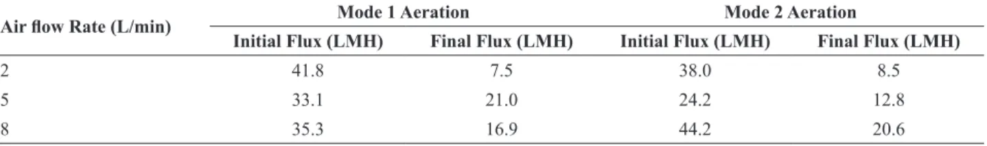
In order to promote a more homogeneous aeration of the bioreactor and inside the membrane module, a diff erent aeration geometry was tested, named Mode 2 aeration (Figure 13). Permeate fl ux behavior was compared for Mode 1 and Mode 2 aeration for the 3/4 in module diameter for three air fl ow rates previously tested. The Figures 14, 15 and 16 present results for 2, 5 and 8 L/min, respectively, and Table 5 exhibits initial and fi nal permeate fl ux values for each condition.
It can be observed that Mode 2 aeration was just better than Mode 1 for 2 L/min air fl ow rate (Figure 14), presenting fi nal normalized fl ux values of 0.24 and 0.19, respectively. For 5 L/min air fl ow rate (Figure 15), Mode 2 aeration was not able to promote aeration homogeneity for Figure 6. Water fl ux vs. transmembrane pressure for two diff erent
membrane modules. Module 1 – 73 LMH/bar; Module 2 – 58 LMH/
0.8 0.85 0.9 0.95 1
300 350 400 450
0 100 200 300 400 500 600
N
orm
al
iz
ed F
lux
A
bsol
ute
P
re
ss
ure
(m
bar)
Time (min)
Absolute Pressure Normalized Flux
Figure 7. Critical fl ux evaluation under respective hydrodynamic
conditions: air fl ow rate of 2 L/min, 3/4 in module diameter and
Mode 1 aeration.
0 0.2 0.4 0.6 0.8 1
0 20 40 60 80 100
N
orm
al
iz
ed F
lux
Time (h)
2 L/min 5 L/min 8 L/min
Figure 8. Normalized permeate fl ux with time for activated sludge
experiments under three diff erent air fl ow rates: 2, 5 e 8 L/min for 3/4
in module diameter.
Table 2. Initial and fi nal hydraulic permeabilities and permeate fl uxes for the three diff erent air fl ow rates and 3/4 in module diameter. Permeate Flux (LMH) Hydraulic Permeability (LMH/bar)
Air fl ow rate (L/min) Initial Final Initial Final
2 41.8 7.5 76.8 35.3
5 33.1 21.0 78.4 33.1
8 35.3 16.9 59.5 33.0
0.3 0.4 0.5 0.6
0.7
0.8 0.9 1
0 20 40 60 80 100
N
orm
al
iz
ed F
lux
Time (h)
2 L/min 5 L/min 8 L/min
Figure 9. Normalized permeate fl ux with time for activated sludge
experiments under three diff erent air fl ow rates: 2, 5 e 8 L/min for 1
in module diameter.
0 0.2 0.4 0.6 0.8 1
0 20 40 60 80 100
N
orm
al
iz
ed F
lux
Time (h)
3/4 in module 1 in module
Figure 10. Normalized fl uxes for 3/4 in and 1 in module diameters
and 2 L/min air fl ow rate.
Table 3. Initial and fi nal hydraulic permeabilities and permeate fl uxes for the three diff erent air fl ow rates and 1 in module diameter. Permeate Flux (LMH) Hydraulic Permeability (LMH/bar)
Aeration Flow Rate (L/min) Initial Final Initial Final
2 35.3 14.5 58.2 31.7
5 32.0 22.8 54.0 35.6
8 33.0 22.5 50.9 30.5
Table 4. Initial and fi nal permeate fl uxes for 3/4 in and 1 in module diameters to 2, 5 and 8 L/min air fl ow rates.
Air fl ow rate (L/min) 3/4 in Module 1 in Module
Initial Flux (LMH) Final Flux (LMH) Initial Flux (LMH) Final Flux (LMH)
2 41.8 7.5 35.3 14.5
5 33.1 21.0 32.0 22.8
I.R. Cadore, M.K. da Silva, L.D. Pollo and I.C. Tessaro
58
0.6
0.7
0.8 0.9 1
0 20 40 60 80 100
Norm
al
iz
ed F
lux
Time (h)
3/4 in module 1 in module
Figure 11. Normalized fl uxes for 3/4 in and 1 in module diameters
and 5 L/min air fl ow rate.
0.4 0.5 0.6
0.7
0.8 0.9 1
0 20 40 60 80 100
N
orm
al
iz
ed F
lux
Time (h)
3/4 in module 1 in module
Figure 12. Normalized fl uxes for 3/4 in and 1 in module diameters
and 8 L/min air fl ow rate.
0 0.2 0.4 0.6 0.8 1
0 20 40 60 80 100
N
orm
al
iz
ed F
lux
Time (h)
Mode 1 Aeration Mode 2 Aeration
Figure 14. Normalized fl ux for Mode 1 and Mode 2 aeration, for 2 L/
min air fl ow rate and 3/4 in module diameter. Figure 15. min air fl ow rate and 3/4 in module diameter.Normalized fl ux for Mode 1 and Mode 2 aeration, for 5 L/ 0.5
0.6
0.7
0.8 0.9 1
0 20 40 60 80 100
N
orm
al
iz
ed F
lux
Time (h)
Mode 1 Aeration Mode 2 Aeration
Table 5. Initial and fi nal permeate fl uxes for Mode 1 and Mode 2 aeration, 2, 5 and 8 L/minair fl ow rates and 3/4 in module diameter.
Air fl ow Rate (L/min) Mode 1 Aeration Mode 2 Aeration
Initial Flux (LMH) Final Flux (LMH) Initial Flux (LMH) Final Flux (LMH)
2 41.8 7.5 38.0 8.5
5 33.1 21.0 24.2 12.8
8 35.3 16.9 44.2 20.6
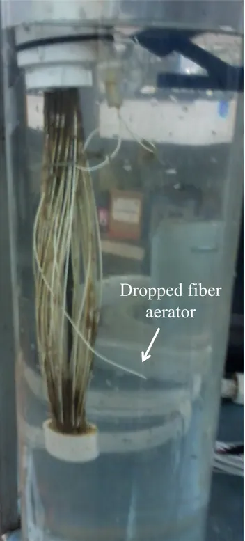
performance improvement. After 50 hours of experiment, the fouling rate increased suddenly and caused permeate flux reduction. In this case, a malfunction of fiber aerators inside the bundle occurred because they were only rolled around the permeation fibers and might be dropped due to a bubble swarm from the bottom aerator (Figure 17).
For 8 L/min air flow rate condition (Figure 16), permeate flux values were very similar for Mode 1 and Mode 2 aeration for almost all times. Even this air flow rate condition presented a similar performance to Mode 1, but did not present better performance results than 5 L/min air flow-rate and the same Mode 2 aeration condition. As can be seen in Figure 18, there is a maximum air flow rate beneficial for process performance, as observed for Mode 1 aeration.
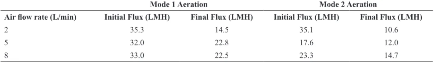
Mode 2 aeration was also tested with the 1 in module diameter, for 2, 5 and 8 L/min air flow rates and results are presented in Figures 19, 20 and 21, respectively. Table 6 presents initial and final permeate fluxes for each condition.
For the 1 in module diameter, Mode 2 aeration showed a similar performance to Mode 1 aeration; only the 2 L/ min air flow rate presented a small difference. It must be mentioned that, for Mode 2 aeration and each air flow rate, comparing only the 3/4 in and 1 in module diameters for each condition, the second presented a better performance for all conditions, enhancing results shown previously about packing density evaluation. Overall results for Mode 2 aeration in comparison with Mode 1 aeration showed that the new aeration geometry did not provoke a performance improvement. Mode 2 aeration design was not satisfactory to promote a better aeration homogeneity inside the fiber bundle; therefore, new aeration designs must be developed.
Organic matter removal
Organic matter removals were obtained by comparing TOC and COD measurements for influent and permeate streams, such that the influent was a synthetic wastewater solution and permeate was collected each 24 hours of experiment. TOC and COD values are presented in Table 7. The number of samples for influent and permeate was 15 and 96, respectively. The table verified the treatment
efficiency for organic matter removal, reaching values for TOC and COD removal of 96% and 93%, respectively.
CONCLUSIONS
A SMBR system provided with PEI hollow fiber membranes was operated in order to investigate hydrodynamics effects such as air flow rate, module packing density and
Dropped fiber
aerator
Figure 17. Photograph of the dropped fiber aerator for Mode 2
aeration and 5 L/min air flow rate.
Figure 16. Normalized flux for Mode 1 and Mode 2 aeration, for 8 L/
min air flow rate and 3/4 in module diameter. 0.4
0.5 0.6
0.7
0.8 0.9 1
0 20 40 60 80 100
N
orm
al
iz
ed F
lux
Time (h)
I.R. Cadore, M.K. da Silva, L.D. Pollo and I.C. Tessaro 60
0.2 0.3 0.4 0.5 0.6
0.7
0.8 0.9 1
0 20 40 60 80 100
N
orm
al
iz
ed F
lux
Time (h)
2 L/min 5 L/min 8 L/min
Figure 18. Normalized flux versus time for Mode 2 aeration, 2, 5 e 8 L/minair flow rates and 3/4 in module diameter.
0.2 0.4 0.6 0.8 1
0 20 40 60 80 100
Norm
al
iz
ed F
lux
Time (h)
Mode 1 Aeration Mode 2 Aeration
Figure 19. Normalized flux for Mode 1 and Mode 2 aeration, for 2 L/
min air flow rate and 1 in module diameter.
0.6
0.7
0.8 0.9 1
0 20 40 60 80 100
N
orm
al
iz
ed F
lux
Time (h)
Mode 1 Aeration
Mode 2 Aeration
Figure 20. Normalized flux for Mode 1 and Mode 2 aeration, for 5 L/
min air flow rate and 1 in module diameter.
0.6
0.7
0.8 0.9 1
0 20 40 60 80 100
N
orm
al
iz
ed F
lux
Time (h)
Mode 1 Aeration Mode 2 Aeration
Figure 21. Normalized flux for Mode 1 and Mode 2 aeration, for 8 L/
min air flow rate and 1 in module diameter
Table 6. Initial and final permeate fluxes for Mode 1 and Mode 2 aeration, 2, 5 and 8 L/minair flow rates and 1 in module diameter.
Mode 1 Aeration Mode 2 Aeration
Air flow rate (L/min) Initial Flux (LMH) Final Flux (LMH) Initial Flux (LMH) Final Flux (LMH)
2 35.3 14.5 35.1 10.6
5 32.0 22.8 17.6 12.0
8 33.0 22.5 23.3 14.7
Table 7. TOC and COD measurements for influent and permeate.
TOC (mg/L) COD (mg/L)
Influent Permeate Influent Permeate
Mean 108 4 149 11
Standart deviation (%) 11 (10%) 1 (25%) 9 (6%) 4 (36%)
Maximum 124 10 162 21
Minimum 92 2 130 3
Removal (%) 96% (92 – 98 %) 93% (87 – 98 %)
aeration system geometry. Three air flow rates were studied (2, 5 and 8 L/min) and the results showed the existence of a threshold value for air flow rate that is beneficial for system performance. Above that value, a better performance cannot be achieved and may even be worse. In this study, the best performance was reached with 5 L/min air flow rate followed by 8 and 2 L/min air flow rates. Packing density of the module also had an effect on system performance in a way that, for two module diameters tested, the best system performance
NOMENCLATURE
COD – Chemical oxygen demand
DMAE – Water and Sewage City Department DO – Dissolved oxygen
J – Permeate flux (SI unit = m3/m2/s; work unit = L/m2/h)
J20 – Permeate flux at temperature of 20 ºC (SI unit = m3/
m2/s; work unit = L/m2/h)
Jp – Permeate flux for hydraulic permeability test (SI unit = m3/m2/s; work unit = L/m2/h)
LMH – Abbreviation of L/m2/h
Lp – Hydraulic permeability (SI unit = m3/m2/s/Pa; work
unit = L/m2/h/bar)
PEI – Poly (ether) imide PVC – Polyvinyl chloride
SEM – Scanning Electron Microscopy SMBR – Submerged Membrane Bioreactor T – Temperature in ºC
TMP – Transmembrane Pressure TOC – Total organic carbon TSS – Total suspended solids VSS – Volatile suspended solids
ΔP – Transmembrane pressure (SI unit = Pa; work unit = mbar)
REFERENCES
APHA, AWWA and WEF. Standard Methods for the Examination of Water and Wastewater. American Public Health Association, American Water Works Association, Water Pollution Control Federation, Washington, D. C., 20th edition (1998).
Braak, E., Alliet, M., Schetrite, S. and Albasi, C. Aeration and hydrodynamics in submerged membrane bioreactors. Journal of Membrane Science, 379, 1–18 (2011).
Chang, I. S., Le-Clech, P., Jefferson, B. and Judd, S. Membrane fouling in membrane bioreactors for wastewater treatment. Journal of Environmental Engineering, 128, 1018–1029 (2002).
Chua, H. C., Arnot, T. C. and Howell, J. A. Controlling fouling in membrane bioreactors operated with a variable throughput. Desalination, 149, 225–229 (2002).
Delgado, S., Villaroel, R. and González, E. Effect on the shear intensity on fouling in submerged membrane bioreactor for wastewater treatment. Journal of Membrane Science, 311, 173–181 (2008).
Field, R. W., Wu, D., Howell, J. A. and Gupta, B. B. Critical Flux Concept for Microfiltration Fouling. Journal of Membrane Science, 100, 259 – 272 (1995).
Fu, H. Y., Xu, P. C., Huang, G. H., Chai, T., Hou, M. and Gao, P. F. Effects of aeration parameters on effluent quality and membrane fouling in a submerged membrane bioreactor using Box–Behnken response surface methodology. Desalination, 302, 33 – 42 (2012).
Gil, J.A., Túa, L., Rueda, A., Montano, B. and Rodriguez, D. P. M. Monitoring and analysis of the energy cost of an MBR. Desalination, 250, 997–1001 (2010).
Jiang, T., Kennedy, M. D., Guinzbourg, B. F., Vanrolleghem, P. A. and Schippers, J. C. Optimising the operation of a MBR pilot plant by quantitative analysis of the membrane fouling mechanism. Water Science and Technology, 51, 19 – 25 (2005).
Lebegue, J., Heran, M. and Grasmick, A. Membrane bioreactor: distribution of critical flux throughout an immersed HF bundle. Desalination, v. 231, p. 245–252 (2008).
Liao, B. Q., Bagley, D. M., Kraemer, H. E., Leppard, G. G. and Liss, S. N. A Review of Biofouling and its Control in Membrane Separation Bioreactors. Water Environmental Research, 76(5), 425-436 (2004).
Melin, T., Jefferson, B., Bixio, D., Thoeye, C., De Wilde, W., De Koning, J., Van Der Graaf, J. and Wintgens, T. Membrane bioreactor technology for wastewater treatment and reuse. Desalination, 187, 271–282 (2006).
Meng, F., Yang, F., Shi, B. and Zhang, H. A comprehensive study on membrane fouling in submerged membrane bioreactors operated under different aeration intensities. Separation and Purification Technology, 59, 91–100 (2008).
Sui, P., Wen, X. and Huang, X. Feasibility of Employing Ultrasound for On-Line Membrane Fouling Control in an Anaerobic Membrane Bioreactor. Desalination, 219, 203– 213 (2008).
Ueda, T., Hata, K., Kikuoka, Y. and Seino, O. Effects of aeration on suction pressure in a submerged membrane bioreactor. Water Research, 31, 489–494 (1997).
Viero, A.F., Sant’anna G.L. and Nobrega Jr., R. The use of polyetherimide hollow fibres in a submerged membrane bioreactor operating with air backwashing. J. Membr. Sci., 302 (1–2), 127–135 (2007).
Wu, J., He, C. and Zhang, Y. Modeling membrane fouling in a submerged membrane bioreactor by considering the role of solid, colloidal and soluble components. Journal of Membrane Science, 397, 102–111 (2012).
Yeo, A. and Fane, A.G. Performance of individual fibers in a submerged hollow fiber bundle. Water Science and Technology, 51, 165–172 (2005).