An Active Se rvice fo r Multicast Vid e o
An Active Se rvice fo r Multicast Vid e o
An Active Se rvice fo r Multicast Vid e o
An Active Se rvice fo r Multicast Vid e o
D istrib
D istrib
D istrib
D istrib u
u
ution
u
tion
tion
tion
Paulo André da Silva Gonç alves , José Ferreira de Rezende and Otto Carlos Muniz Bandeira Duarte
Paulo André da Silva Gonç alves , José Ferreira de Rezende and Otto Carlos Muniz Bandeira Duarte
Paulo André da Silva Gonç alves , José Ferreira de Rezende and Otto Carlos Muniz Bandeira Duarte
Paulo André da Silva Gonç alves , José Ferreira de Rezende and Otto Carlos Muniz Bandeira Duarte
Grupo de Teleinformática e Automaç ão - GTA
Programa de Engenharia Elé trica – COPPE
Universidade Federal do Rio de Janeiro
Cx. P. 68504 - 21945-970 - Rio de Janeiro RJ - Brazil
{apaulo, rezende, otto}@gta.ufrj.br
Abstract This paper proposes a service for multicast video distribution based on the active network para-digm. Active nodes can provide soft-state and perform customized computations on a per-user or per-application basis. These functionalities allow the deployment of an efficient and flexible ser-vice that can dynamically adjusts itself to the bandwidth availability. The source learns about the best transmission rate of the video by receiving feedback messages from receivers.A fusion mechanism is used to prevent feedback-message implosion.Simulation results show that a capsule filtering level of 96% can be achieved by using the fusion mechanism.
Keywords: video distribution, active networks, multicast, adaptive service.
1 Introduction
Broadcast and cable TV systems are characterized by the transmission of a fixed-bandwidth video signal to homogeneous receivers. Aside from the signal-to-noise ratio available at each receiver, all receivers experience the same video quality. On the other hand, video distribu-tion over the Internet has distinct characteristics[1,2,3]. First, video information is packetized and packets are routed hop-by-hop from source to receivers. Second, the network bandwidth is dynamically shared by several concurrent applications. Finally, receivers differ in proc-essing capacities and available bandwidth along their individual path from the source. In addition, the Internet makes interactivity easier while allowing users to receive information with respect to their own interest. Therefore, new applications for video distribution over the Internet must offer different quality levels and allow receivers to specify their individual video quality requirements.
Approaches based on layered or hierarchical coding
are the most used to distribute video with different qual-ity levels. In the layered coding scheme, the video signal is encoded into one or more layers of different priorities. The highest priority layer, called base layer, provides a basic level of quality. To refine incrementally this qual-ity, enhancement layers with progressively lower priori-ties are encoded. A variety of proposals for multicasting layered video can be found in the literature [1, 4, 5].
A novel paradigm in network architectures, called ac-tive networks [6, 7, 8, 9, 10] has recently been proposed. An active network is an intelligent network that supports dynamic modification of its behavior as seen by users. Applications can perform customized computations into the network by injecting their programs embedded in packets called capsules. While allowing on-the-fly cus-tomizations to meet application needs, active networks can provide a much more flexible network architecture [11, 12, 13].
service to adapt to the available bandwidth on the paths from the source to the receivers. Furthermore, the service uses a single multicast tree for distributing layered video and it prevents receivers from interfering with each other when they attempt to receive a better video quality. Feedback capsules from receivers inform the source about the best video transmission rate. To prevent feed-back-capsule implosion, a fusion mechanism is used. We also evaluate the performance of this mechanism.
The remainder of this paper is organized as follows. Section 2 describes the proposed active service. Section 3 presents the implemented protocol. Simulation results are presented in Section 4. Finally, Section 5 concludes the paper.
2 The Active Service
The proposed service is based on a receiver-driven approach in which receivers decide the video quality that they are willing to receive. Because of its flexibility, the service adjusts itself to the available bandwidth and the individual requests made by receivers. Receivers are able to connect/disconnect from the service as many times as they want and anytime during a session.
The offered active service enhances characteristics pro-vided by the RLM (Receiver-driven Layered Multicast) [5] protocol that is based on the passive network paradigm. In the RLM, each layer is sent out on a single multicast tree identified by different multicast addresses. Thus, each receiver can subscribe to a number of layers that can be supported by its individual path from the source. To im-prove the current video quality, a receiver must carry out an experiment by subscribing to the next layer and measur-ing packet loss. If the loss rate exceeds a threshold, the receiver concludes that there is no available bandwidth and unsubscribes to the experimented enhancement layer. Since these experiments may incur in network congestion and thus impacting losses, receivers will interfere with each other. Furthermore, establishing multiple multicast trees, one for each video layer, means to keep more states at routers. This has the side effect of limiting the number of layers that the network can support and thus decreasing the quality granularity offered to the receivers.
Our service requires a layered video source with QoS (Quality of Service) dynamic control, i.e. the source gener-ates an on-demand and controlled number of layers. The source learns about the best video transmission rate by periodically receiving feedback capsules from receivers. In this manner, the source is able to add or remove layers in order to generate a number of layers suitable for a range of path characteristics and provide a service that best meets
the receiver’s needs.
Video data capsules carry the video information of each layer. The routing of these capsules is aided by forwarding pointers in the soft-state provided by active nodes. A video data capsule routes itself along paths that lead to interested receivers only if the bandwidth avail-ability permits.
Figure 1 illustrates the active service when three lay-ers are encoded, at 1 Mbps each, by the video source. Link capacities and the video quality desired by each receiver are presented in this figure. All receivers, except the fourth, receive a number of layers suitable to the available network bandwidth. Although the fourth re-ceiver could receive the second enhancement layer, it is only receiving its desired video quality of 2 Mbps, that is, the base layer and the first enhancement layer. Each re-ceiver can attempt to increase its received video quality by using the quality adjustment scale at its own conven-ience. The upper bound on the scale is related to the processing capacity of the receiver in decoding video. Suppose that the third receiver disconnects from the ser-vice. Then the source will only generate two layers to avoid waste of network bandwidth.
Figure 1 - Example of the layered video distribution.
3 The Active Protocol
3.1 Subscribe/Maintenance Capsules
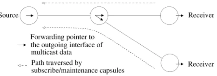
The function of the subscribe/maintenance capsules is the construction and maintenance of a multicast distribu-tion tree. Receivers interested in the video recepdistribu-tion must periodically send these capsules towards the source. Once the capsule goes towards the source, it installs forwarding pointers in the soft-state to permit video data capsules to know the paths that lead to receivers. Figure 2 illustrates this idea.
Figure 2 – Multicast tree formation
Subscribe/maintenance capsules must periodically re-fresh forwarding pointers installed in the soft-state pro-vided by active nodes. To avoid subscribe/maintenance capsule implosion, customized computations into the network are performed. These computations filter unnec-essary capsules, in such a way that only one sub-scribe/maintenance capsule traverses the complete path to the source [14, 15, 10].
3.2 Availability Capsules
To aid the routing of video data capsules, the avail-ability capsules construct an availavail-ability table at each node they pass through. The node's auxiliary table con-tains a list of the maximum video transmission rate through each outgoing interface belonging to the multi-cast tree. The availability capsules also construct at each node, except at the receivers, an auxiliary table related to the availability table. From the standpoint of a node, these tables contain both the desired video quality by downstream neighbor nodes belonging to the multicast tree and a reference to the interface that allows to reach each of these neighbors.
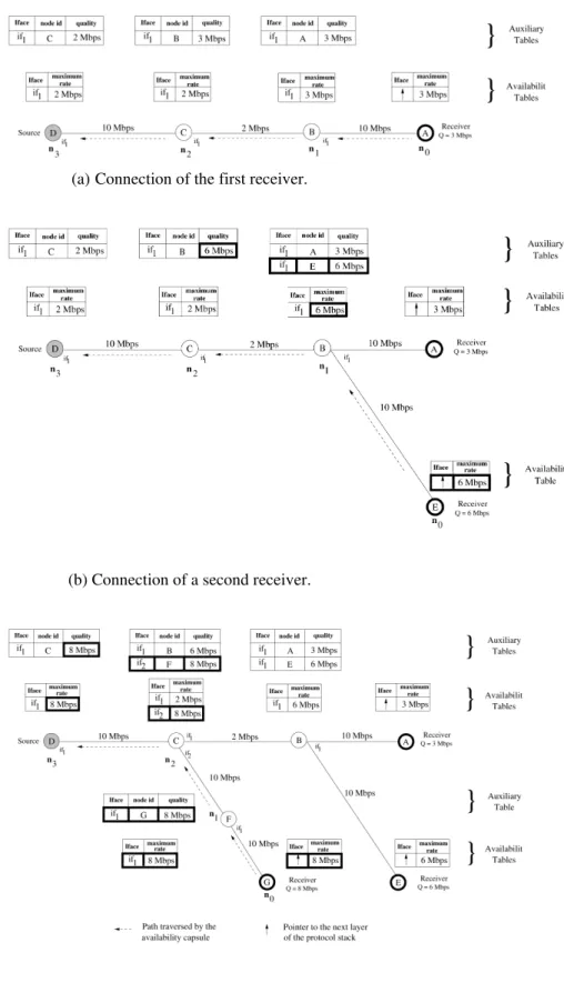
Figure 3(a) shows how these tables are constructed due to the connection of the first receiver (A) to the ser-vice. Nodes have been numbered with respect to the standpoint of this receiver. Each node has an identifier indicated inside it. Each link capacity is indicated on the respective link. Immediately after sending the first sub-scribe/maintenance capsule, the receiver sends an avail-ability capsule that carries its desired video quality Q. This information is carried in a capsule header field (TX) and is expressed in terms of bandwidth. The receiver's availability table only contains one entry that informs the
parameter Q. Upon reaching n1, the capsule constructs an auxiliary table. This table contains an entry that is a compound of the identifier of the previous node visited by the capsule, the TX value carried by the capsule and the interface that permits to reach the previous node. Next, the capsule verifies the available bandwidth for the video on the link to the previous node. The capsule assigns in the node's availability table the minimum value between the available bandwidth for the video and the indicated quality in the auxiliary table. The capsule updates its TX field with this minimum value and follows to the next node. The same algorithm is performed when the capsule passes through n2 and n3. Upon receiving the capsule, the source knows exactly how many layers to generate in order to better serve the receiver.
Figure 3(b) illustrates how the second receiver (E) connects to service. Both receivers A and E are intercon-nected to node B through the same interface and they have the same available bandwidth to receive video. Node numbering is related to the standpoint of the re-ceiver E. After constructing the availability table in E, the availability capsule sent by the receiver reaches n1 carry-ing in the TX field the video quality desired by E. A new entry into the availability table that contains the tuple {if1,
E, 6 Mbps} is added. The new value of the maximum video transmission rate on interface 1 is computed as the minimum value between the available bandwidth for video on the link to receiver E and the maximum value among all qualities related to interface 1 in the auxiliary table. The field TX is updated with this computed value and the capsule follows to n2. At this node, the entry in the auxiliary table is updated with the TX value. Next, it is computed the minimum value between the available bandwidth for the video and the value in the auxiliary table field labeled quality. The entry in the availability table as well as the TX field are updated with this infor-mation, and next, the capsule follows to n3. The steps executed in order to update the tables at this node are the same described above.
(a) Connection of the first receiver.
(b) Connection of a second receiver.
(c) Connection of a third receiver
Figure 3(c) illustrates the receiver G connecting to the service. The algorithm performed to construct the tables on n0 and n1 follows the same steps described above. In
particular, note that the interface 2 of the node n2 is now
included into its tables. Upon reaching n2, the availability
capsule adds a new entry into the auxiliary table. This entry represents the quality desired by the neighbor node F, which is reachable through interface 2. The new entry in the availability table is computed as the minimum value between the bandwidth availability for the video on the link to the previous node F and the value of quality related to interface 2 in the auxiliary table. That is, the minimum value between 10 Mbps and 8 Mbps. Entries related to interface 1 are not considered. With the new information about the interface 2 in the availability table, the capsule updates its TX field with the maximum value observed in this table and follows to n3. Note that, in this
case, data related to all interfaces in the availability table were considered.
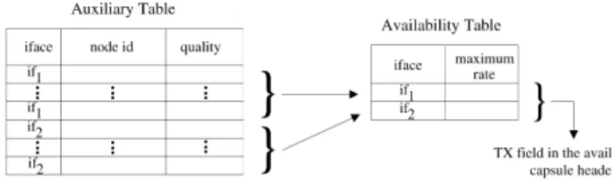
Figure 4 summarizes the relationship among entries in the auxiliary table, entries in the availability table, and the information placed in the TX field of a capsule sent to the next node towards the source. Each entry in the avail-ability table is obtained by comparing a subset of entries in the auxiliary table with the available bandwidth for the video on the link reachable through the interface related to this subset of entries. All entries in the avail-ability table are taken into account in order to compute the value set in the TX field of the capsule.
Figure 4 - Summary of the relationship between entries in the auxiliary
table, entries in the availability table, and the field TX of the capsule to
be sent to the next node.
More generally, the algorithm performed to add or update an entry in the auxiliary table follows equation 1.
(1)
where i is the incoming interface of the capsule, represents, from the standpoint of the node n, the quality desired by the node n-1, which is reachable through interface i. The value carried in the TX field of a capsule upon leaving node n-1 is represented by TXn-1.
The algorithm performed to add or update an entry in the availability table follows equation 2.
(2)
where i is the incoming interface of the capsule, bn (i)
represents the available bandwidth for video on the link that is reachable through interface i of the node n. If n≥1, tx n
(i)
represents the maximum video transmission rate on the link reached through interface i. Otherwise, it repre-sents the quality Q desired by the receiver. The number of auxiliary table entries related to interface i is repre-sented by σ(i). Values from Λn
1,(i)
to Λn
σ(i),(i)
represent entries related to interface i in the auxiliary table field labeled quality in the node n.
Equation 3 gives the value of the field TX in the cap-sule that will go towards the source.
(3)
where Q is the video quality, in terms of bandwidth, desired by the receiver. TXn represents the TX field value in the availability capsule header upon the capsule leav-ing node n. The number of entries in the availability table is represented by θ. Values from Ω1
n to Ω
θ
n represent
entries in the field labeled maximum rate in the availabil-ity table of node n.
3.2.1 The Feedback Mechanism
A feedback mechanism is used in order to keep the video source updated about the better video transmission rate. Thus, all receivers must periodically send availabil-ity capsules towards the source. Note that interactivavailabil-ity among source and receivers is achieved since the source can adjust itself according to the information carried by the capsules. This information represents, straightfor-wardly or indirectly, the desired video quality by each receiver or the video quality supported by the network. Quality adjustments carried out by receivers are auto-matically placed into the new availability capsules that go towards the source.
3.2.2 The Fusion Mechanism
The drawback of periodically sending availability capsules towards the source is twofold. First, updates in the availability and auxiliary tables will be uncoordi-nated, and second, the source will be prone to feedback-capsule implosion.
1
, 1 ) ( 1 ,=
≥
Γ
−TX
n−for
n
i n n ) ( 1 , i n n −
Γ
}
{
=
≥
≥
Λ
Λ
=
0
,
1
;
1
),
,...,
(
max
min
) ( ) ( ) ( , 1 ) 1 ( ) ( ) (n
if
Q
for
n
if
b
tx
i i n i n n n i iσ
σ{
max( ,..., ), 1; 1 0 ,1 Ω ≥ ≥
Ω
=
=
θ ifn forϑn if Q
n n n
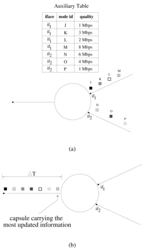
Figure 5 gives an idea about the first drawback. In this figure, an active node has two incoming interfaces of availability capsules. There are four entries related to interface 1 and two related to interface 2 in its auxiliary table. Capsules from the indicated nodes in the table arrive through these interfaces. Each capsule updates its respective entry in the auxiliary and availability tables, carrying to the next node the maximum value observed in the availability table. Considering that these capsules arrive at the node in a short time period, the update of these tables will be uncoordinated. Each capsule will perform its function and follow to the next node, without regarding near incoming capsules. Furthermore, by con-sidering this short time period, only the last capsule will carry the most updated information.
(a)
(b)
Figure 5 - A drawback of periodically sending availability capsules towards the source.
In order to solve the problems described above, a fu-sion mechanism is used. The fufu-sion of availability cap-sules occurs according to the following conditions: (1) at least one availability capsule related to each entry in the auxiliary table has arrived; (2) the fusion timer has ex-pired. Figure 6(a) illustrates the first condition. One capsule related to each entry in the auxiliary table has
arrived at the node before the expiration of the fusion timer. In this case, on the last expected capsule arrival, entries in the auxiliary table related to each cached cap-sule are updated according to equation 1. Next, based on equation 2, the availability table is completely updated and only one availability capsule follows to the next node, carrying in TX the result given by equation 3. To update an availability table entry, at least one capsule from the interface related to this entry must be in the node's cache. Figure 6(b) illustrates the second condition. In this case, availability capsules related to only two entries in the auxiliary table have arrived. After the expi-ration of the fusion timer, the respective auxiliary table entry for each cached capsule is updated following equa-tion 1. Upon finishing these updates, based on equaequa-tion 2, the entries in the availability table are updated. Next, only one capsule follows to the next node carrying in TX the result of equation 3 . If more than one capsule related to the same auxiliary table entry arrives before the expi-ration of the fusion timer, then the previous cached cap-sule is dropped. Thus, only the most updated information will be used during the fusion.
(a) (b)
Figure 6 - The fusion mechanism.
3.3 Video Data Capsules
A video data capsule uses the information in its TX field and the information in the availability table to make routing decisions. Such decisions include dropping itself, and reproducing or deploying copies of itself on the ap-propriate outgoing interfaces. In order to aid a capsule to make such decisions, the source assigns the field TX of each video data capsule with the cumulative rate for the layer that the capsule belongs to, that is, the field TX is assigned according to the following rule:
(4)
∑
=
≤
≤
=
ci
i
for
c
N
TC
TX
1
where c is the layer that the capsule belongs to, TCi
denotes the rate of the ith layer and N is the maximum number of layer that the source can generate.
Upon arriving at a node, the video data capsule checks whether there is soft-state for its multicast group. If there is no soft-state, then the capsule drops itself, otherwise, it verifies in the availability table if the maxi-mum rate on each interface is greater than or equal to the value placed in its TX field. If true, the capsule follows through this interface. If more than one interface respect this condition, the video data capsule must reproduce or deploy copies of itself on these interfaces. If there are no interfaces that respect this condition, then the capsule drops itself. Thus, with the mechanism for constructing and maintaining the multicast tree combined with the filtering performed by video data capsules, the service eliminates the need for establishing multiple trees for multicasting layered video. There is only a single multi-cast tree that is traversed by base layer capsules. Cap-sules of each enhancement layer can traverse all or some branches of this tree.
With the mechanism for constructing and updating the availability tables combined with the filtering per-formed by the video data capsules, receivers get a num-ber of layers according to the characteristic of their indi-vidual path from the source and their desired video qual-ity Q.
4 Results
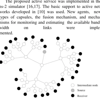
The proposed active service was implemented in the ns-2 simulator [16,17]. The basic support to active net-works developed in [10] was used. New agents, new types of capsules, the fusion mechanism, and mecha-nisms for monitoring and estimating the available band-width on links were imple-mented.
Figure 7 - Network topology used in simulations.
Figure 7 shows the network model used to evaluate the performance of the fusion mechanism. Link capaci-ties are 10 Mbps. Each link delay was randomly chosen uniformly on the interval [1, 10] ms. The timeout interval of the fusion timer was set to 100 ms. The start-time of each receiver was randomly chosen uniformly on the interval [0, 10] s. Each simulation was run for 100 sec-onds. Results presented throughout this section have a confidence interval of 90%.
Figure 8 - Availability capsule filtering level.
Figure 8 shows how the filtering level of availability capsules varies with the sending interval of these cap-sules. The filtering level is defined as the percentage of the total number of availability capsules suppressed into the network. The curve shows an availability capsule filtering level from 91% to 96%. The maximum filtering levels are observed when the sending interval of the availability capsules is less than 25 ms, or equal to or half of the timeout interval of the fusion timer.
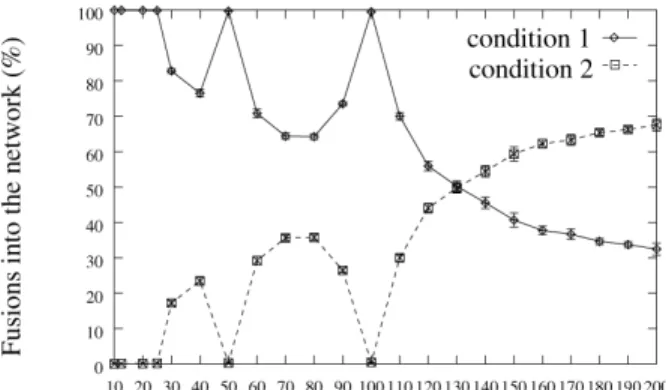
Figure 9 - Behavior of the fusions into the network
Figure 10 shows the behavior of the average interval arrivals of availability capsules at the source according to the availability capsule sending interval. This result shows that when the sending interval is less than 25 ms, or equal to or half of the timeout interval of the fusion timer, the average interval arrivals of availability cap-sules is almost the same of the sending interval of the availability capsules specified at receivers.
Figure 10 - Average interval arrivals of availability capsules.
As a final result, Figure 11 shows the percentage of availability capsule replacements for a range of availabil-ity capsule sending intervals. Replacements are only considered at the first intermediate node, from receiver to source, that has more than one entry in its auxiliary ta-ble. This result shows the waste of availability capsules sent by receiver. The curve shows that less than 0.06% of availability capsules are replaced when the sending interval is 10 ms. As this interval increases, this
percent-age reduces, becoming zero from the sending interval of 100 ms.
Figure 11 - Availability capsule replacements.
5 Conclusions
In this paper, we have presented an active service for multicast video distribution. Receivers can change their video quality requirements as many times as they want and anytime during a session. Requests posed by receiv-ers are accepted depending only on the bandwidth avail-ability. In contrast with the service provided by the RLM protocol, the proposed active service avoids the interfer-ence caused by a receiver that attempts to receive a better videoquality. Furthermore, the active service achieves a layered video distribution using a single multicast tree. This result is a consequence of the mechanism for con-structing and maintaining the multicast tree associated with the filtering performed by video data capsules. The performance of the fusion mechanism results on a high level of capsule filtering, from 91% to 96%, which makes evident the scalability of the service.
Acknowledgements
This work was supported by UFRJ, FUJB, CNPq, CAPES, COFECUB, FAPERJ and REENGE.
References
[1] X. Li, S. Paul and M. H. Ammar. Layered Video Multi-cast with Retransmission (LVMR): Evaluation of Hier-archical Rate Control. In IEEE INFOCOM'98, San Francisco, California, pages 1062-1072, 1998.
An Improved MPEG behavioral Analysis with Autonomous Parameter-Extracting Algorithm for Strict Video Applications. In IEEE ICC'2000, New Orleans, USA, pages 831-835, 2000.
[3] M. D. Amorim and O. C. M. B. Duarte. A Novel Deterministic Traffic Model Based on a Two-level Analysis of MPEG Video Sources. In IEEE GLOBECOM'98, Sydney, Australia, pages 244 -249, 1998.
[4] L. Wu, R. Sharma and B. Smith. ThinStreams: An Architecture for Multicasting Layered Video. In NOSSDAV'97, 1997.
[5] S. McCanne, V. Jacobson and M. Vetterli. Re-ceiver-driven Layered Multicast. In Proc. of SIG-COMM'96, Stanford, CA, 1996.
[6] J. Biswas et al. The IEEE P1520 Standards Initia-tive for Programmable Network Interfaces. IEEE Communications Magazine, 36(10):64-70, 1998. [7] K. L. Calvert, S. Bhattacharjee and J. Sterbenz.
Directions in Active Networks. IEEE Communica-tions Magazine, 36(10):72-78, 1998.
[8] D. L. Tennenhouse, J. M. Smith, W. D. Sincoskie and D. Wetherall. A Survey of Active Network Research. IEEE Communications Magazine, 35(1):80-86, 1997.
[9] D. L. Tennenhouse and D. J. Wetherall. Towards an Active Network Architecture. Computer Com-munication Review, 26(2):5-18, 1996.
[10] F. P. Junqueira and O. C. M. B. Duarte.
Comuni-cação Multiponto Confiável para Estações Móveis em Redes Ativas. In XVII Simpósio Brasileiro de Redes de Computadores SBRC'99, Salvador, BA, Brazil, pages 389-404, 1999.
[11] D. Feldmeier et al. Protocol Boosters. IEEE Jour-nal on Selected Areas in Communications, 16(3):437-444, 1998.
[12] W. S. Marcus et al. Protocol Boosters: Applying Programmability to Network Infrastructures. IEEE Communications Magazine, 36(10):79-83, 1998. [13] U. Legedza, D. Wetherall and J. Guttag. Improving
the Performance of Distributed Applications Using Active Networks. In IEEE INFOCOM'98, San Francisco, CA, pages 590-599, 1998.
[14] D. J. Wetherall, J. V. Guttag and D. L. Tennen-house. ANTS: A Toolkit for Building and Dy-namically Deploying Network Protocols. In IEEE OPENARCH'98, San Francisco, CA, 1998. [15] D. J. Wetherall, J. V. Guttag and D. L.
Tennen-house. ANTS: Network Services Without the Red Tape. In IEEE Computer, 32(4):42-48, 1999. [16] K. Fall and K. Varadhan. NS Notes and
Documen-tation. Technical report, The VINT Project, July 1999.