*e-mail: [email protected]
Plasma Nitriding of CA-6NM Steel: Effect of H
2+ N
2Gas Mixtures
in Nitride Layer Formation for Low N
2Contents at 500 °C
Angela Nardelli Allensteina, Carlos Maurício Lepienskib,
Augusto José de Almeida Buschinellic, Silvio Francisco Brunattod,*
a
Engineering Post-graduate Program (PIPE), Federal University of Parana – UFPR,
CEP 81531-990, Curitiba, PR, Brazil
b
Department of Physics, Federal University of Parana – UFPR,
CEP 80230-901, Curitiba, PR, Brazil
c
Department of Mechanical Engineering, Federal University of Santa Catarina – UFSC,
CEP 88040-900, Florianópolis, SC, Brazil
d
Department of Mechanical Engineering, Federal University of Parana – UFPR,
CEP 81531-990, Curitiba, PR, Brazil
Received: October 1, 2010; Revised: December 13, 2010
This work aims to characterize the phases, thickness, hardness and hardness profiles of the nitride layers formed on the CA-6NM martensitic stainless steel which was plasma nitrided in gas mixtures containing different nitrogen amounts. Nitriding was performed at 500 °C temperature, and 532 Pa (4 Torr) pressure, for gas mixtures of 5% N2 + 95% H2, 10% N2 + 90% H2, and 20% N2 + 80% H2, and 2 hours nitriding time. A 6 hours nitriding time condition for gas mixture of 5% N2 + 95% H2 was also studied. Nitrided samples results were compared with non-nitrided condition. Thickness and microstructure of the nitrided layers were characterized by optical microscopy (OM), using Villela and Nital etchants, and the phases were identified by X-ray diffraction. Hardness profiles and hardness measured on surface steel were determined using Vickers hardness and nanoindentation tester, respectively. It was verified that nitrided layer produced in CA-6NM martensitc stainless steel is constituted of compound layer, being that formation of the diffusion zone was not observed for the studied conditions. The higher the nitrogen amounts in gas mixture the higher is the thickness of the nitrided layer and the probability to form different nitride phases, in the case γ’-Fe4N, ε-Fe2-3N and CrN phases. Intrinsic hardness of the nitrided layers produced in the CA-6NM stainless steel is about 12-14 GPa (~1200-1400 HV).
Keywords: plasma nitriding, Low N2 content gas mixtures, ASTM CA-6NM martensitic stainless steel, nanoindentation technique
1. Introduction
The martensitic wrought stainless steels, CA-6NM, were developed in Suisse to improve the weldability of conventional martensitic stainless steels as, for example, the ASTM CA-15. Classified by ASTM as a soft stainless steel, CA-6NM was evaluate to attend the market which needs steels with superior mechanical properties and facilities to fabricate. This stainless steel after tempering presents excellent mechanical properties, as high strength, cavitation erosion and adequate toughness, even at low temperatures. In addition, due to its high hardenability, CA-6NM is utilized in diverse applications, normally in the manufacturing of large pieces as hydraulic turbine rotors, pumps and compressors1-3.
Otherwise, nitriding is a thermochemical surface treatment widely used to treat steels and alloys. The main advantages of nitriding are the improvement of wear and frictional properties, corrosion and fatigue resistance4. Plasma nitriding5-7 is one of the most versatile nitriding processes with many advantages over the conventional salt-bath and gas nitriding, and it has been widely used in many industrial applications to improve the wear and fatigue resistance.
As pointed out by literature8,9 the presence of alloying elements, particularly nitride formers, has a strong influence on the hardening, morphology and kinetics characteristics of the nitrided surface. The influence of nitride former elements is dependent on the degree
of interaction with nitrogen. Elements as Al and Ti have a strong interaction with nitrogen, while the interaction of Cr is dependent of the alloying element content on steel. It is considered chromium contents higher than 5.6 wt. (%) leads to strong nitrogen interaction characteristics.
Pinedo and Monteiro10 studied the plasma nitriding kinetics of AISI 420 martensitic stainless steel. Nitriding was performed at 480, 500, 520, 540 and 560 °C temperatures, to 4 hours, using a gas mixture of 75% N2 + 25% H2, and pressure of 250 Pa (1.87 Torr). For all the nitriding temperatures, the nitrided surface was comprised by both the compound layer and the diffusion zone, even at lower temperatures, as a result of the high nitrogen potential on the gas mixture. The maximum nitriding surface hardness was 1500 HV0.025. The hardness profiles show a step shaped decrease from the maximum hardness to the core hardness. This behavior is a consequence of the complex nitriding reactions that take place at the interface, and reflects the nitrogen compositional profile across the nitrided case.
558 Allenstein et al. Materials Research
2. Materials and Methods
Samples were prepared from a cast CA-6NM martensitic stainless steel, which was received in the 22 HRC hardness tempered condition. The chemical composition in wt. (%) was 0.032% C, 12.25% Cr, 4.42% Ni, 0.63% Mn, 0.522% Si, 0.43% Mo and Fe balance, and the microstructure is comprised of martensitic matrix (α) with some dispersed austenite (γ). Before nitriding, the samples were cut for 20 × 30 × 10 mm dimensions, ground and polished using 1 µm Al2O3 solution, in accordance with the conventional metallographic preparation.
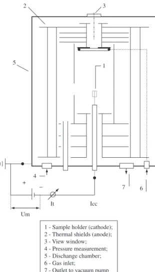
The plasma nitriding apparatus is shown in Figure 1. Nitriding was performed at 500 °C temperature, at 532 Pa (4 Torr) pressure, gas flow of 240 sccm (4.00 × 10⁻⁶ standard m3/s), for 2 and 6 hours nitriding times, using different gas mixtures of 20% N2 + 80% H2, 10% N2 + 90% H2 and 5% N2 + 95% H2. The discharge chamber consisted of a stainless steel cylinder 350 mm in diameter and 380 mm in height. Samples were placed in the cathode and were negatively biased in a selected potential, using a square waveform pulsed power supply of 3.6 kW. The potential was specified to 660 ± 20 V and the power transferred to the plasma was adjusted by varying the time switched on (ton) of the pulse. The ton of the pulse could be varied from 10 to 220 µs and the total on/off time was 240 µs. The sample temperature was varied by adjusting the on/off time of the pulsed potential and was measured using a chromel/alumel (type K) thermocouple that is placed into the sample holder, which is inserted 12 mm into the sample. The 1.5 mm diameter thermocouple is electrically isolated with Al2O3 and is protected with a stainless steel cover.
Prior to nitriding, the system was evacuated to a residual pressure of 2.6 Pa (2 × 10⁻² Torr). The N
2 (99.999% pure) and H2 (99.999%
pure) gas mixtures were obtained adjusting datametrics mass flow controllers whose full scale value was the same for both, in such case 500 sccm (8.33 × 10⁻⁶ standard m3/s).
The total gas flow was set to 240 sccm (4 × 10⁻⁶ standard m3/s) in order to maintain the specified atmosphere of the discharge. The pressure in the vacuum chamber was adjusted by manual valves and measured using a capacitance manometer of 1.33 × 10⁴ Pa (100 Torr) full scale. Heating rates on the order of 15 °C/min was employed to reach the plasma nitriding temperature. Prior to nitriding, the samples were cleaned in a H2 glow discharge at a pressure of 400 Pa (3 Torr) and at a temperature of 300 °C during 10 minutes.
The nitrided samples were cross-section cut for microstructural analysis. The surfaces were then ground and polished with 1 µm diamond paste, and after etched by two different etchants, Vilella and 2% Nital solution. Optical microscopy analysis was performed in a Olympus PME equipment. Microhardness measurements were performed using a HMV Microhardness Tester Schimadzu equipment, with 100 g load for profiles determination and 500 g load for surface measurements. The nanoindentation technique was executed on nitrided and non-nitrided samples. The equipment utilized was a Nanoindenter XP - MTS Systems, with 40 g (400 mN) load and 10 seconds loads time. Finally, X-ray diffractometry (XRD) analysis was performed on surfaces of nitrided samples, using a Shimadzu equipment, for 1.54 nm wave-length (λ) copper tube.
3. Results and Discussion
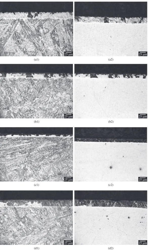
Figure 2 shows typical microstructures after the nitriding treatments, which were etched by Vilella (Index 1) and Nital (Index 2). It is possible to verify the Nital etching made possible to reveal the nitrided layers for all the studied conditions. The same was not verified for the respective substrate bulks. This result clearly indicates as the nitriding process develops, the chromium alloying element is kept
in solid solution in the substrate bulk, and the stainless characteristic is kept unaltered in such region. Otherwise, in the nitrided layer, the nitrogen diffusion into surface, allied to the high chromium-nitrogen affinity at the considered temperature tends to result in chromium nitride precipitation. Such assumption is in accordance with the X-ray diffraction results presented ahead. As a consequence of the strong solid solution chromium depletion close to surface, the nitrided layer was also revealed using Nital etchant. It is to be noted Nital is a non-adequate etchant for stainless steels. Such result must be emphasized, since the use of Nital solution, in this case, would permit to indicate if the surface was nitrogen sensitized due to the nitriding treatment for the considered material. Moreover, such result indicates Nital solution as etchant could be utilized as a direct method to determine if the stainless characteristic of the stainless steel in the nitrided layer region is maintained unaltered after nitriding treatments. The above mentioned is based confronting both the nitrided layer and bulk regions aspects at micrographs shown in Figure 2a2, b2, c2, d2. In addition, the use of Nital solution facilitated the determination of the nitriding depth in the present work. Otherwise, Vilella etchant was responsible by etching similarly the nitrided layer and bulk regions, resulting in visual contrast slight differences of both the regions, as shown in Figure 2a1, b1, c1, d1.
It is to be emphasized nitriding layer is normally composed of compound layer and diffusion zone. For the processing conditions and characterization techniques adopted in the present work it was
560 Allenstein et al. Materials Research not possible to observe any diffusion zone. Such fact could be related
to its very small thickness, due to short nitriding times utilized here. This assumption is in agreement with Li and Bell results11, which demonstrated a very thin diffusion zone was obtained in martensitic stainless steel for 20 hours nitriding time at 500 °C (10 and 3.33 times higher, and at the same nitriding temperature utilized here).
Table 1 shows the thickness of the nitriding layer obtained for all the studied conditions. It can be verified the higher the nitrogen content in gas mixture the higher is the thickness of the nitriding layer, the same occurring for higher nitriding times. Thicknesses of 25.0, 20.0 and 12.5 µm were measured for 20, 10 and 5% N2 gas mixtures and 2 hours processing conditions, respectively. The increase of nitriding time for 6 hours, using 5% N2 gas mixture, resulted in thickness of 25.0 µm. Table 1 also presents hardness measurements of the samples surface. Hardness values of 1240, 1172 and 950 HV0.5 were determined for nitrided layers produced after nitriding times of 2 hours and using gas mixtures containing 20, 10 and 5% N2, respectively. The compound layer produced using 5% N2 showed lesser hardness than 1200-1300 HV probably due to the elastic-plastic deformation field which reaches non-nitrided substrate (the bulk), as a consequence of the high testing load that was utilized, in the case 500 g, and the small layer thickness, which was only of 12.5 µm, as previously presented. In such case, hardness tests must be carried out applying low loads to prevent this kind of error in measurement. It is to be noted different studies have recommended that maximum penetration depths do not reach 1/10 and 1/20 of the layer thickness, respectively, for very hard and soft materials12,13. Otherwise, the
increase of nitriding time for 6 hours, using 5% N2 gas mixture, resulted in hardness of 1173 HV0.5 (Table 1).
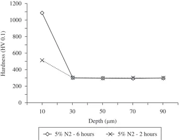
Figures 3 and 4 show hardness profiles of processed samples as a function of the gas mixture and nitriding time, respectively. Hardness values of 800, 800 and 500 HV0.1 were measured at depth of 10 µm, inside the compound layer, for 20, 10 and 5% N2 gas mixtures and 2 hours processed conditions, respectively. The increase of nitriding time for 6 hours, using 5% N2 gas mixture, resulted in hardness of 1100 HV0.1 at depth of 10 µm, inside the compound layer. For all studied conditions, measurements performed at 30 µm depth, comprising the hardness of the bulk, indicated values on the order of 300 HV0.1.
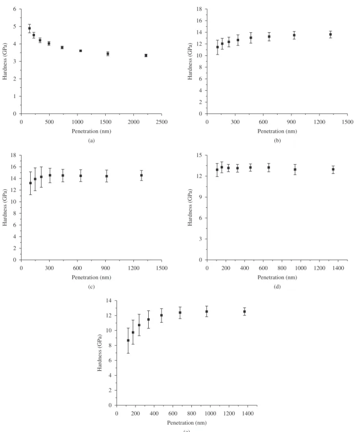
Figure 5 presents result of nanoindentation as a function of the indenter penetration, which was obtained by varying the applied loads up to 40 g (400 mN). For non-nitrided condition, the high hardness values about 4 - 5 GPa (~ 400 - 500 HV), related to indenter penetrations up to 500 nm, could be probably explained by the occurrence of surface work hardening generated during polishing step, at the sample preparation procedure, which would be in accordance with Pethica et al. study14. For higher loads resulting in 2250 to 2500 nm indenter depth, the measurements values tend to the substrate bulk hardness, in the case 3 GPa (~ 300 HV). For 20, 10, and 5% N2, and 2 hours nitriding conditions, the values of 13 (~ 1300 HV), 14 (~ 1400 HV) and 12 GPa (~ 1200 HV), respectively, are in agreement with the expected for surface hardness measurements. Confronting such results and the obtained by Vickers hardness tester (Table 1), nanoindentation resulted in higher measurement values to the last two nitriding conditions (10 and 5% N2). This fact is related to the smaller thickness of the respective compound layers and the strong differences in the applied loads in both the characterization techniques, in the case 40 g maximum load and 500 g for nanoindentation and Vickers hardness measurement techniques, respectively. In such case, the very high applied load utilized for hardness determination results in a higher penetration of the Vickers indenter, which probably overtook the compound layer, entering in the substrate bulk region. Finally, for 5% N2 and 6 hours nitriding condition, values of 12 GPa (~1200 HV) obtained for penetrations higher than 500 nm are in agreement with microhardness measurements (Table 1). The small hardness values for penetrations up to 500 nm are probably due to the surface roughness, as a consequence of the longest time that the sample was exposed to plasma species bombardment.
Table 1. Compound layer thickness and the respective surface hardness values for different nitriding conditions.
Nitriding condition
Thickness of compound layer
(µm)
Surface hardness (HV0.5)
20% N2 – 2 hours 25.0 1240
10% N2 – 2 hours 20.0 1172
5% N2 – 2 hours 12.5 950
5% N2 – 6 hours 25.0 1173
Non-nitrided - 250
Figure 3. Hardness profiles of processed samples as a function of the gas mixture.
Figure 5. Nanoindentation results for different nitriding conditions: a) Non-nitrided; b) 20% N2 – 2 hours; c) 10% N2 – 2 hours; d) 5% N2 – 2 hours; and e) 5% N2 – 6 hours.
The effect for which smaller hardness values are verified for small penetrations in the nitrided layer was also verified for all nitriding conditions comprising 2 hours nitriding time (Figure 5b, c, d). The variation of the hardness values along the first 300 nm is higher as the nitrogen content in gas mixture is increased, which results in stronger sputtering effect, leading to the obtainment of a higher roughness surface.
562 Allenstein et al. Materials Research
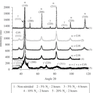
and in the start phases peak enlargement. The peak enlargement is more evident for α−(FeCr) phase, and the obtainment of expanded martensite has been considered in the present case. In addition, it is to be noted the 20% N2 and 2 hours nitriding condition also resulted in the formation of iron nitrides, which were identified as γ’-Fe4N and ε-Fe2-3N phases.
The fact the iron nitrides precipitation only occurred for the highest %N2 gas mixture must be explained. Considering the iron nitrides are metastable phases, results indicate the probability of
γ’-Fe4N and ε-Fe2-3N formation is very small for nitriding conditions comprising lower %N2 gas mixtures. In such case, smaller amounts of nitriding reactive species could be available in glow discharge for 5 and 10% N2 gas mixtures. An assumption the nitriding reactive species as atomic nitrogen would preferentially react with chromium alloying element, in the compound layer, is supported by the fact the chromium forms stable nitrides, which present negative formation Gibbs Free Energy Variation (∆G) for the specified nitriding temperature. So, the higher the nitrogen amounts in gas mixture the higher is the probability to form different nitrides in compound layer. It is to be noted the same argument, id est., a higher amount of available nitriding reactive species for higher %N2 gas mixtures can be utilized to explain the nitrided layer thickness evolution as function of gas mixture as previously presented (Table 1).
4. Conclusions
The main conclusions of the present work can be listed as follows:
• Thehigherthenitrogenamountsingasmixturethehigheris
the probability to form different nitride phases in compound layer, in the case γ’-Fe4N and ε-Fe2-3N and CrN phases, and the higher is the thickness of the nitrided layer, for the studied conditions;
• The hardness of the nitrided layers formed on CA-6NM
stainless steel surface ranged from 12 to 14 GPa at penetration depths about 500 nm;
• Thenanoindentationhardnessresultsareinaccordancewith
Vickers hardness measurements for the studied nitrided layers.
• Thehardnessvaluesasafunctionoftheindenterpenetration,
for penetrations smaller than 500 nm, are strongly dependent of the studied processing conditions; and
• Nitalsolutionasetchantcouldbeutilizedasadirectmethodto
determine if the stainless characteristic of the stainless steel in the nitrided layer region is maintained unaltered after nitriding treatments.
Acknowledgments
The authors would like to thank the Brazilian Agency CNPq for financial support to perform this research, and LACTEC-UFPR by supplying the CA-6NM stainless steel samples.
References
1. Crawford JD. CA6NM an Update. In 29th Annual Steel Founder’s Society of America Technical and Operating Conference Proceedings. USA; 1974. p. 1-13.
2. Gooch TG. Heat Treatment of Welding 13%Cr-4%Ni Martensitic Stainless Steel for Sour Service. Welding Research Supplement. 1995; 213-222.
3. Bilmes PD, Llorente CL and Pérez IJ. Toughness and microstructure of 13Cr4NiMo high strength steel welds. Journal of Materials Engineering and Performance. 2000; 9:609-615.
4. Sun Y and Bell T. Plasma surface engineering of low alloy steel. Materials Science and Enginering A. 1991; 140:419-434.
5. Edenhofer B. Physical and Metallurgical Aspects of Ionnitriding. Heat Treatment Metals Part 1. 1974; 23-28.
6. Rie K-T. Recent Advances in plasma diffusion processes. Surface and Coatings Technology. 1999; 112:56-62.
7. Berg M, Budtz-Jørgensen CV, Reitz H, Schweitz KO, Chevallier J, Kringhøj P et al. On Plasma Nitriding of Steels. Surface and Coatings Technology. 2000; 124:25-31.
8. Jack DH and Jack KH. Invited review: Carbides and Nitrides in Steel. Materials Science and Engineering. 1973; 11(1):1-27.
9. Lightfoot J and Jack DH. Kinetics of Nitriding With and Without Compound Layer Formation. In Proceedings of Heat Treatment’ 73. London, UK; 1973. p. 59-65.
10. Pinedo CE and Monteiro WA. On the kinetics of plasma nitriding a martensitic stainless steel type AISI 420. Surface and Coatings Technology. 2004; 179:119-123.
11. Li CX and Bell T. Corrosion properties of plasma nitrided AISI 410 martensitic stainless steel in 3.5% NaCl and 1% HCl aqueous solutions. Corrosion Science. 2006; 48:2036-2049.
12. Johnson KL. The correlation of indentation experiments. Journal of Mechanics and Physics of Solids. 1970; 18:115-126.
13. Zielinski W, Huang H and Gerberich WW. Microscopy and microindentation mechanics of single crystal Fe-3 wt.% Si: Part II. TEM of the indentation plastic zone. Journal of Materials Research, 1993; 8(6):1300-1310.
14. Pethica JB, Hutchings R and Oliver WC. Hardness measurement at penetration depths as small as 20 nm. Philosophical Magazine A. 1983; 48(4):593-606.