*e-mail: romulorms@gmail.com
Cathodic Cage Plasma Nitriding of Austenitic Stainless Steel (AISI 316):
Influence of the Working Pressure on the Nitrided Layers Properties
R.R.M. de Sousaa*, F.O. de Araújob, L.C. Gontijoc, J.A.P. da Costad, I.O. Nascimentoe, C. Alves Jre
aGrupo de Pesquisa em Materiais e Metrologia, Departamento de Mecânica, Instituto Federal de Educação, Ciência e Tecnologia do Piauí – IFPI, Teresina, PI, Brazil bDepartamento de Ciências Exatas e Naturais, Universidade Federal Rural do Semi-Árido – UFERSA,
Mossoró, RN, Brazil
cCoordenadoria de Ciência e Tecnologia – Física, Instituto Federal do Espírito Santo – IFES, CEP 2904-780 Vitória, ES, Brazil
dDepartamento de Física, Universidade do Estado do Rio Grande do Norte – UERN, Mossoró, RN, Brazil
eLaboratório de Processamento de Materiais por Plasma – LabPlasma, Departamento de Física, Universidade Federal do Rio Grande do Norte – UFRN,
Campus Universitário, CEP 59072-970 Natal, RN, Brazil
Received: May 3, 2013; Revised: November 20, 2013
In this work, the inluence of working pressure on the characteristics of the layers produced by the nitriding treatment on the AISI 316 austenitic stainless steel surface using the Cathodic Cage Plasma Nitriding technique (CCPN) is assessed. The treatments were carried out at a temperature of 723 K for 5 hours under working pressures of 120, 250 and 500 Pa. The morphology, microstructure and corrosion resistance were studied through optical microscopy, x-ray diffraction, and electrochemical potential curves. We analyzed the effects of working pressure on the layer thickness, microhardness and corrosion resistance. The E×i curves and the electrochemical impedance of polarized samples were measured in order to investigate the effect of the ion transfer inside the produced ilm placed into the anodic solution. The electrochemical impedance of the ilms were measured, and showed an apparent capacitive behavior. For treatment under a pressure of 120 Pa we found the nitrides Fe3N,
Fe4N and CrN. For treatment at a pressure of 250 Pa, the CrN disappears and the observed phases are the nitrides Fe3N, Fe4N and the S-phase. For a treatment pressure of 500 Pa there is an increase in the corrosion resistance of nitrided layers, conirmed by the predominance of S-Phase in the x-ray diffraction pattern. On the other hand, the sample nitrided under the pressure of 250 Pa showed very unstable impedance behavior when immersed in NaCl solution, indicating that the treatment at this speciic working pressure has a negative effect on the corrosion resistance of plasma nitrided AISI 316 stainless steel surfaces.
Keywords: cathodic cagetechnique, AISI 316, corrosion resistance, working pressure
1. Introdution
Stainless steel is of great use in engineering due to its high resistance to corrosion, presenting, however, low wear resistance and reduced microhardness. These last two properties are significantly improved through
ionic nitriding1-3. It is known that the nitriding of
austenitic stainless steel at temperatures superior to 723 K produces layers having good wear resistance and
elevated microhardness. However, due to chromium nitride
precipitation the corrosion resistance decreases due to chromium depletion in the adjacent regions of the matrix. On the other hand, when the nitriding treatment is carried out at lower temperatures, the formation of chromium nitride is inhibited due to a decrease in the diffusion of chromium, and a nitrogen supersaturated phase called expanded austenite
(γN), or S-phase, which possesses elevated microhardness
and wear resistance associated with a good corrosion resistance4-10, is formed.
Control of the nitriding process parameters11,12 has
been carried out in order to improve the supersaturated layer (S-phase), which is a solid solution of nitrogen in the austenite phase, presenting a good thickness and adherence to the substrate, making possible an effective improvement in the supericial microhardness and corrosion resistance of the materials. The treatment time and temperature have been the mostly used parameters in the plasma nitriding processes for modifying the microstructure and phase composition of the formed layers, determining important physical and chemical properties of the nitrided layer such as nitrogen incorporation2,10,13.
supericial characteristics of the modiied layers have been receiving special attention in conventional plasma nitriding treatment, as have the inluence of the treatment under different pressures in R.F. plasma nitriding processes17,18
and ionic implantation by immersion19. However, in cathodic
cage plasma nitriding the inluence of the working pressure on the physical and chemical properties of the treated surfaces has hardly been studied. This technique uses the same equipment as the conventional nitriding process but with the addition of a new set-up introduced by the addition of a cage on the working table as shown in Figure 1. The cage has a cylindrical shape with a top lid, made of a 0.9 mm thick perforated austenitic stainless steel sheet, with uniformly distributed round holes of 10 mm diameter.
In order to ill this need, we investigate the inluence of work pressure on the physical and chemical properties of the layers produced by the nitriding of the surface of stainless steel ANSI 316 using the cathodic cage plasma
nitriding technique12,20.
2. Material and Methods
2.1.
Experimental procedures
The samples, cut in disc specimens of 12 mm diameter 10mm height made of AISI 316 stainless steel with a chemical composition(wt. %) of 16-18%Cr; 10-14%Ni; 2-3%Mo; 0,08%C; 2%Mn; 1%Si; 0,04%P; 0,03%S; 0.02%Al and Fe (balance), were plasma-nitrided using the cathodic cage plasma technique with the following treatment parameters: a treatment temperature of 723 K, during 5.0 hours, at three different working pressures (120, 250, and 500 Pa). The cage has a cylindrical shape with 112 mm diameter and 25 mm of height, made of 0.8 mm thick austenitic stainless steel AISI 316 perforated sheet which had equally distributed round holes of 8 mm diameter. The samples were placed on the workpiece which was insulated
from the cathode by an alumina disc, in order to maintain the samples under a loating potential.
A schematic diagram of the experimental arrangement is shown in Figure 1. The nitriding atmosphere consisted of a mixture of 80 vol. % N2 - 20 vol. % H2 in a total low of 20 sccm. After the treatment, the samples were cooled inside the camera under a nitrogen low until reaching a temperature of 353 K in order to reduce the risks of oxidation.
After a mechanical polishing with SiC paper, the samples were attacked with an acid solution (75% HCl + 25% HNO3) to make optical metallography. The microstructure of the layers were analyzed using an optical microscope (Olympus BX60M), and the phase composition was analyzed using x-ray diffraction (XRD) operated with Cu Kα radiation (α = 1.540 Å) at 40 KV (Shimadzu, XRD-6000). The micro-hardness (HV) of the treated surfaces was measured with a micro-hardness test Pantec, model 1000 used in the Vickers mode with a charge of 100g.
The corrosion resistance of the sample surface modiied by plasma nitriding were evaluated at room temperature using metallographic examination, electrochemical impedance spectroscopy, and the potentiodynamic anodic polarization curves obtained in a cell with 3,5 wt.% NaCl solution in distilled water. The cell was in a three-electrode setup: a saturated calomel electrode (SCE), a platinum auxiliary electrode and a working electrode (sample), using a scan rate of 1.0 × 10⁻³ V/s.
3. Results and Discussion
3.1.
Characterization of nitrided layers
The measured values of the working pressure, microhardness tests and corresponding layer thickness are presented in Table 1. Note that the thickness of the layers varies inversely with working pressure.
The reduction of the layer thickness as a function of increase in working pressure is the opposite of the behavior
that is observed in conventional ionic nitriding for this range of working pressure. This behavior occurs because, in the cathodic cage technique, an increase in working pressure causes a decrease in the mobility and in the mean free path of the ions, consequently decreasing the number of ions that reach the internal surface of the cage holes which are responsible for the hollow cathode effect, sputtering ions from their surface. On the other hand, when the working pressure in the chamber decreases, the number of ions that reach the hole surface is increased and the sputtered ions from this surface increase the ion low that reaches the substrate, producing a more eficient deposition on the surface of the sample21,22. Since the samples are under a
loating potential and the ion plasma density is low, any deleterious effects on the surface of the samples (substrate) are negligible. In this way, any specimen that is deposited on the substrate remains on the surface until absorbed by diffusion to form the new phase underneath the surface.
In the cathodic cage technique, unlike in conventional
ionic nitriding, there is no competition between adsorption and sputtering of the specimens that are deposited on the surface. On the other hand, in conventional ionic nitriding when an increase on the gas pressure occurs the effect of the deposition is dominant with respect to the sputtering produced by the ions on the sample surface producing
a thicker layer. However, this increase is limited by the
saturation of nitrogen in the surface, since in a pressure of the order of 100 to 200 Pa, the thermodynamic equilibrium of nitrogen plasma species19,23 occur.
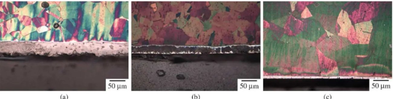
Figure 2 shows the microstructure on the cross-section of the layers nitrided at 723 K, for 5.0 hours, at different pressures (120, 250, and 500 Pa) by cathodic cage plasma nitriding. The optical micrographs of the samples nitrided at 120 Pa (Figure 2a), 250 Pa (Figure 2b) and 500 Pa (Figure 2c) show the austenitic substrate and a thin top layer with thickness of about 64.5, 31.6, and 12.5 µm,
respectively, identiied by XRD as the γ’-Fe4N, ε-Fe3N, and
CrN in Figure 2a, as the γ’-Fe4N, ε-Fe3N, and S-phase in Figure 2b, and inally as the S-phase in Figure 2c.
The microhardness tests indicate that a smaller value was obtained for the layer of the sample nitrided at 500 Pa, due to the predominant presence of S-phase as shown in the X-rays diffractogram (Figure 3). Results presented in the micrographs are consonant with the analyses of diffraction presented in Figure 3. A bright region, characteristic of the expanded austenite (S-phase), is observed on samples nitrided at 250 Pa and 500 Pa. These layers show a predominance of S-phase, as can be observed in x-rays diffractograms. However, the sample nitrided at 120 Pa does not present this bright region, as conirmed by the absence of S-phase in the X-ray diffractograms (Figure 3). The greater thickness of the layer for the sample nitrided at 120 Pa can be explained by the formation of chromium nitrides and the decomposition of metastable phase (expanded austenite) into more stable phases (iron nitrides).
This result is in consonance with layers formed on glass substrate samples, where we have only the deposition process of compounds formed in the bulk plasma24.
3.2.
Resistance to corrosion
3.2.1. NaCl 3,5% Solution
Figure 4 displays the anodic polarization curves for the untreated and cathodic cage plasma nitrided AISI 316L stainless steel samples in 3,5 wt. % NaCl solution. Polarization curves indicate that anodic behavior depends on the partial pressure of the gases involved in the nitriding process. Apparently the anodic polarization
curves moves to lower currentdensity when the partial
pressures increases. It means that the anodic dissolution current for the layer formed on austenitic stainless steel is small when the pressure is increased, indicating that the corrosion resistance of the nitrided layer formed depends on the working pressure. The corrosion current density obtained by the Tafel extrapolation method also indicate that the corrosion resistance of the nitrided layers depends on the working pressure, since their values decrease with pressure, which is highlighted in the inset of Figure 4. The inset igure presents the logarithm of corrosion current density as a function of the nitriding working pressure. It is observed that there is an exponential relationship between the increase of pressure and corrosion current density. This result is in agreement with the polarization
Figure 2. OM cross-sectional views of the samples nitrided by Cathodic Cage Plasma Nitriding at (a) 120 Pa, (b) 250 Pa, and (c) 500Pa. Table 1. Measures of thickness and microhardness of the cathodic
cage AISI 316 steel nitrided samples. Treatment time of 5 hours at 723 K , under different working pressures.
Working pressure [Pa]
Layer tickness [µm]
Microhardness (HV0,1)
120 64.5 980
250 31.6 1175
curves and x-ray difractograms of the nitrided samples, since they indicate that an increase in pressure produces an increase in the formation of S-phase, thus favoring an
increase in the corrosion resistance. It can be observed that
the anodic behavior of the matrix in chloride solutions is represented by a curve with an active dissolution at low potentials, followed by a region of approximately constant current density and a pitting potential around 0.39 V, which
represents a drop in the passivity, indicating the pitting formation. This also appears in the sample nitrided at a pressure of 500 Pa, with a higher pitting potential, as can be seen in Figure 4. While susceptibility to pitting of the untreated sample and the nitrided sample under a pressure of 500 Pa are similar, the samples treated at pressures of 120 Pa and 250 Pa did not show a well deined pitting potential and had a lower pitting susceptibility (see Figure 4).
Figure 3. X-rays diffractograms of the samples nitreded using Cathodic Cage technique at 450 °C during 5 h at different working pressures.
Electrochemical impedance spectroscopy (EIS) experiments were carried out in NaCl 3.5 wt. % solution, after a stabilization time of 1800 seconds, at potentials equal to Ecor determined by Tafel analysis as well as by the open circuit potential (OCP). All spectra were acquired over a frequency range of 1.0 × 10⁴ Hz to 4.0 × 10⁻² Hz using
an automated Ivium impedance analyzer. The equivalent electrical circuits (Figure 5) are proposed based on the simulation of the EIS data for the corrosion behavior of the ilms. The results are similar to that proposed in other thin ilm (ZnO) studied for the untreated and for the sample nitride at 500 Pa pressure, e.g.25,26. However the samples
treated at pressures of 120 and 250 Pa showed a different
circuit as shown in Table 2 and Figure 5. This fact also conirms that the properties of ilms formed depends on the working pressure.
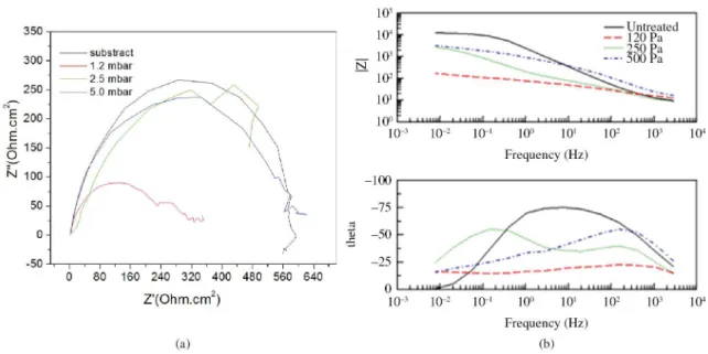
Figure 6 displays the Nyquist plots for the EIS study as measured by immersion in 3.5 wt.% NaCl solution on the cathodic cage plasma-nitrided samples surface. The proile of the plots reveals a semicircle. The diameter of the
semicircles increaseswith increase of the working pressure. The extended curve of the semicircle will intercept the horizontal axis at two points. As the distance between these interceptions is used to estimate the resistance to corrosion, we reafirm the dependence of corrosion resistance on the working pressure. The results are represented in the Table 2,
Figure 5. Equivalent circuits proposed for simulating the electrochemical response in 3.5 wt. % NaCl solution: (a) untreated and treated at 500 Pa; (b) 120 and 250 Pa.
Table 2. Values of elements in equivalent circuit to it the (combined with) impedance spectra for untreated samples and samples treated at different pressures (120, 250, and 500 Pa), immersed in 3,5 wt.% NaCl solution.
R1 R2 CPE1-T CPE1-P R3 CPE2-T CPE2-P
Untreated 7.4 1990 5.76E-5 0.870
120 Pa 12.4 1638 1,66E-5 0.840 0.5 1.525E-5 0.329
250 Pa 7.6 155.6 8.39E-4 0.558 3853 1.517E-3 0.781
500 Pa 13.7 3841 1.70E-5 0.874
where R1 represents the resistance of corrosive medium in the solution (i.e., 3.5 wt.% NaCl) and R2 the polarization resistance of the ilm formed on the sample surface by the plasma-nitrided technique, whereas CPE1 displays the constant phase element equivalent to capacitance of the electrical layer. In these cases the diameter of the semicircle which corresponds to the corrosion resistance for each ilm has a smaller value for the sample formed at a pressure of 120 Pa compared to the other samples therefore the corrosion rate for this ilm is expected to be the largest. The element R1 refers to the resistance of the electrolyte which is approximately constant for all samples. We observe for the sample treated under the pressure of 250 Pa an increase for the parameter CPE1-T and a decrease for R2 value - resistant polarization - indicating a passive layer with more defects or less thick. On the other hand, values of R2 and CPE1-P for the sample formed under the pressure of 500 Pa had the highest values. This indicates a higher capacitive degree of the passive layer formed during the treatment, due to a passive layer with fewer defects, thicker or with better
density.
In the case of the sample formed at a pressure of 250 Pa the values of R2 and CPE1-P decreases, this may be due to leakage current in electrical layers. This leakage current
leads to corrosion acceleration that may be attributed to the
porosities or any other problem produced on the ilm, due to previous corrosion, thus allowing the electrolyte to access the subjacent substrate so that the dissolved substrate also affects the total corrosion of the ilms, including changing the resistance of corrosive medium in the solution (R1), as shown in Table 2. The EIS study conirms the results of dc-polarization in Figure 6.
According to the Bode plot (Figure 6b) the samples formed under pressures of 120 and 500 Pa showed a rapid decrease of impedance in the capacitive region, which is characteristic of the pitting process on stainless steel. Furthermore, the phase angle (θ) tends toward zero at low frequencies, indicating that the resistance of the barrier layer was reached. These changes in the spectra at very low frequencies indicate the occurrence of pitting and are
in agreement with visual inspection. On the other hand, the sample nitrided under the pressure of 250 Pa; shows two time constants, resulting from the presence of structural differences in the oxide ilm formed on the metallic material.
The impedance and phase angle values in the low frequency region are associated with a layer rich in chromium oxide at the interface of the metal. As can be seen phase angle of the sample decreased. This may be due to the chromium depletion in the treated surface which prevents the formation of a good passive layer which could effectively protect the surface from the aggressive environment.
4. Conclusions
The thicker layer, obtained at lower pressures, is due to the increase in the mean free path of the particles that reach the holes of the cathodic cage, increasing the rate of sputtering in these holes surface, and, as no sputtering occurs on the sample surface, since it is under a loating potential, as a consequence there is an increase in the deposition rate forming thicker layers.
On the other hand the hardness decreases as the working pressure increases due to the lower layer thickness. However, for a higher working pressure the predominance of S-phase occurs as shown in the x-rays diffractograms,
indicating that there is an increase in the corrosion resistance
of nitrided layers, conirmed by the polarization curves. Furthermore, there are other factors, such as the chemical attack used for optical metallographic analysis that may modify this behavior, since the sample with the highest percentage of S-phase treated at a pressure of 500 Pa did not present the best corrosion resistance.
Therefore, using cathodic cage plasma nitriding technique, the working pressure control allows one to obtain processed layers of different thicknesses and/or
with high corrosion resistance and good microhardness
value. In this work where the treatment time was 5 hours the best conditions obtained for mechanical properties was for a pressure of 250 Pa indicating that we need a longer treatment time for a working pressure of 500 Pa in order
to obtain thicker layers and better corrosion resistance as
should be expected due the predominance of the S-phase.
Acknowledgments
This work was partially supported by CAPES and CNPq and the used stainless steel was supplied by Villares
Metals S.A.
References
1. Zang ZL and Bell T. Structure and corrosion resistance of
plasma nitrided stainless steel. Surface Engineering. 1995; 1(2):131.
2. Menthe E and Rie KT. Further investigation of the structure and properties of austenitic stainless steel after plasma nitriding.
Surface and Coatings Technology. 1999; 116-119:199-204.
http://dx.doi.org/10.1016/S0257-8972(99)00085-7
3. Cheng Z, Li C X, Dong H and Bell T. Low temperature plasma
nitrocarburising of AISI 316 austenitic stainless steel. Surface
and Coatings Technology. 2005; 191:195-200. http://dx.doi.
org/10.1016/j.surfcoat.2004.03.004
4. Menthe E, Bulak A, Olfe J, Zimermann A and Rie KT.
Improvement of the mechanical properties of austenitic
stainless steel after plasma nitriding. Surface and Coatings
Technology. 2000; 133-134:259-263. http://dx.doi.org/10.1016/
S0257-8972(00)00930-0
5. Li CX and Bell T. Corrosion properties of active screen plasma
nitrided 316 austenitic stainless steel. Corrosion Science. 2004;
46:1527-1547. http://dx.doi.org/10.1016/j.corsci.2003.09.015
6. Samandi M, Shedden BA, Smith DFI, Collins GA, Hutchings R and Tendys J. Microstructure, corrosion and tribological behaviour of plasma immersion ion-implanted austenitic
stainless steel. Surface and Coatings Technology. 1993; 59:261.
http://dx.doi.org/10.1016/0257-8972(93)90094-5
implanted austenitic stainless steel. Materials Science and
Engineering: A. 2001; 303:163. http://dx.doi.org/10.1016/
S0921-5093(00)01841-4
8. Ichii K, Fujimura K and Takase T. Structure of the ion-nitrided layer of 18-8 stainless steel. Technology Reports of the Kansai University. 1986; 27:135.
9. Angelini E, Burdese A and DeBenedetti B. Ion-Nitriding of
Austenitic Stainless SteelMetall. SciTechnol. 1988; 6:33.
10. Marchev K, Cooper CV, Blucher JT and Giessen BC. Conditions for the formation of a martensitic single-phase compound layer in ion-nitrided 316L austenitic stainless steel.
Surface and Coatings Technology. 1998; 99:225. http://dx.doi.
org/10.1016/S0257-8972(97)00532-X
11. Li CX, Georges J and Li XY. Active screen plasma nitriding of
austenitic stainless steel. Surface Engineering. 2002; 18(6):453-458. http://dx.doi.org/10.1179/026708402225006240
12. Alves C Jr, Araujo FO, Ribeiro KJB, Costa JAP, Sousa RRM
and Sousa RS. Use of cathodic cage in plasma nitriding. Surface
and Coatings Technology. 2006; 201:2450-2454. http://dx.doi.
org/10.1016/j.surfcoat.2006.04.014
13. Bacci T, Borgioli F, Galvanetto E and Pradelli G.
Glow-discharge nitriding of sintered stainless steels. Surface
and Coatings Technology. 2001; 139:251. http://dx.doi.
org/10.1016/S0257-8972(01)01010-6
14. Priest JM, Baldwina MJ and Fewella MP. The action of
hydrogen in low-pressure r.f.-plasma nitriding. Surface and
Coatings Technology. 2001; 145:152-163. http://dx.doi.
org/10.1016/S0257-8972(01)01311-1
15. Alves C Jr, Rodrigues JA and Martinelli AE. Effect of pulse width on the microstructure of d.c.-plasma-nitrided layers.
Surface and Coatings Technology. 1999; 122:112-117. http://
dx.doi.org/10.1016/S0257-8972(99)00326-6
16. Alves JR C, Silva EF and Martinelli AE. Effect of workpiece
geometry on the uniformity of nitrided layers. Surface and
coating Technology. 2001; 139:1-5.
17. Borgioli F, Fossati A, Galvanetto E, Bacci T and Pradelli G. Glow discharge nitriding of AISI 316L austenitic stainless steel: inluence of treatment pressure. Surface and Coatings
Technology. 2006; 200:5505-5513. http://dx.doi.org/10.1016/j.
surfcoat.2005.07.073
18. Baldwin MJ, Fewell MP, Haydon SC, Kumar S, Collins GA, Short KT et al. Rf-plasma nitriding of stainless steel. Surface
and Coatings Technology. 1998; 98:1187. http://dx.doi.
org/10.1016/S0257-8972(97)00150-3
19. Fewell MP, Mitchell DRG, Priest JM, Short KT and Collins GA. The nature of expanded austenite. Surface and Coatings
Technology. 2000; 131:284.
http://dx.doi.org/10.1016/S0257-8972(00)00793-3
20. Sousa RRM, Araujo FO, Ribeiro KJB, Mendes MWD, Costa
JAP and Alves Jr C. Cathodic cage of samples with different
dimensions. Materials Science and Engineering: A. 2007;
465:223-227. http://dx.doi.org/10.1016/j.msea.2007.03.007
21. Moller W, Parascandola S, Telbizova T, Günzel R and Richter
E. Surface processes and diffusion mechanisms of ion nitriding of stainless steel and aluminium. Surface and Coatings
Technology. 2001; 136:73-79.
http://dx.doi.org/10.1016/S0257-8972(00)01015-X
22. Dimitrov VI, D’haen J, Knuyt G, Quaeyhaegens C and Stals LM. A method for determination of the effective diffusion coefficient and sputtering rate during plasma diffusion
treatment. Surface and Coatings Technology. 1998; 99:234-241. http://dx.doi.org/10.1016/S0257-8972(97)00530-6
23. Jeong B-Y and Kim M-H. Effects of the process parameters on
the layer formation behavior of plasma nitrided steels. Surface
and Coatings Technology. 2001; 141:182-186. http://dx.doi.
org/10.1016/S0257-8972(01)01232-4
24. Araujo FO, Sousa RRM, Costa JAP and Alves Jr C. Deposition of metallic ilms on glass substrate using Cathodic Cage Technique. Revista Brasileira de Aplicações de Vácuo. 2009; 27:149-152.
25. Lin J-C, Chuang C-L, Lai C-M, Chu H-C and Chen Y-S. On the oxygen reduction reaction catalyzed by Ti -Cu binary ilms in 0.5 M sulfuric acid solution. Thin Solid Films. 2009; 517:4777-4781.
26. Al-Hardan NH, Abdullah MJ, Ahmad H, Abdul Aziz A and
Low LY. Investigation on UV photodetector behavior of RF-sputtered ZnO by impedance spectroscopy. Solid-State
Electronics. 2011; 55:59-63. http://dx.doi.org/10.1016/j.