Channel Estimation in Link Adaptation Strategies
for MIMO-OFDM Systems
Darlan Cavalcante Moreira, and Charles Casimiro Cavalcante
Abstract— Multiple transmit-and-receive antennas jointly with orthogonal frequency division multiplexing (OFDM) provide a high number degrees of freedom for link adaptation according to the wireless channel condition. In this paper we analyze the impact of two different channel estimation techniques in the link adaptation of MIMO-OFDM wireless systems. We propose to add the choice of the channel estimation technique according to the redundancy and error caused by each strategy, which can be measured in terms of a degradation in the goodput of the system.
Index Terms— Channel Estimation, Link Adaptation, MIMO-OFDM systems
I. INTRODUCTION
One of the most challenging issues for the future wireless communication systems is the provision of quality-of-service (QoS) guarantees and high transmission rates to users over the harsh wireless channels given the limited resource availability. In this context, MIMO-OFDM (Multiple Input Multiple Out-put - Orthogonal Frequency Division Multiplexing) systems have attracted much attention since they have the multiplexing and/or diversity gain of MIMO systems and the multipath resistance of OFDM systems. In fact, using MIMO it is even possible to obtain high spectral efficiency such as 20-40 bits/Hz [1] when the channel is favorable, or a large diversity gain using space-time block codes [2] when the channel presents deep fade. However, since most MIMO techniques were developed for flat fading channels, OFDM is used to provide a flat fading channel per subcarrier making possible the use of MIMO in wideband channels. Moreover, the use of OFDM allows the MIMO block coding (in case of diversity gain) to be also performed as space-frequency or space-time-frequency block code, instead of only space-time block code [3].
Indeed, channel estimation plays a key role in MIMO-OFDM systems. It is not only necessary to adapt the system to the current channel situation, but it is also essential to the MIMO-OFDM detection since it makes possible the filtering of the different information in the case of multiplexing gain or the decode process in the case of diversity gain. This optimization of the system parameters can be seen in higher layers as a greater throughput.
The remainder of this paper is organized as follows. In Section II we describe the system model with Sections A, II-B and II-C dedicated to Channel Model, MIMO Architecture and Channel Estimation Techniques, respectively. In Section
The authors are with the Grupo de Pesquisa em Telecomunicac¸ ˜oes Sem-Fio - GTEL, Federal University of Cear´a, C.P. 6005, CEP: 60455-760, Fortaleza-CE, Brazil; email{darlan, charles}@gtel.ufc.br.
III we present the link adaptation concept in the context of Hybrid MIMO-OFDM systems. In Section IV we provide some simulation results and in Section V we highlight our conclusions.
II. SYSTEMMODEL
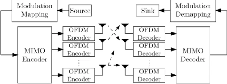
Now, we briefly describe the channel model, the MIMO architecture and the channel estimation techniques utilized. A general MIMO-OFDM system withNttransmit antennas and
Nr receive antennas is shown in Figure 1. In Section II-A
we describe the channel model used in this paper, in Section II-B we briefly discuss the Hybrid MIMO Architectures and in Section II-C we describe the channel estimation techniques used in this paper.
.. . Source
MIMO Encoder Modulation
Mapping
MIMO Decoder Sink ModulationDemapping
OFDM Encoder
OFDM Decoder
OFDM Encoder
OFDM Encoder
OFDM Decoder
OFDM Decoder
.. .
Fig. 1. General MIMO-OFDM System
A. Channel Model
The channel impulse response is given by
h(t, τ) =
Ntaps−1
X
k=0
γk(t)c(τ−τk), (1)
wheretk is the delay of thekth path,γk(t)is the
correspond-ing complex amplitude and c(t) is the shaping filter. Due to motion of the transmitter, receiver and the obstacles in the environment, γk(t)’s are wide-sense stationary narrow-band
complex Gaussian process which are independent for different paths. The values of τk and the statistical moments of γk
depend on the delay profiles and dispersion of the wireless channel. We use those values according to the COST259 Typ-ical Urban channel model [4]. Also, the channel for different pairs of transmit and receive antennas are considered to be uncorrelated [5-7].
From Equation 1, the frequency response at timet is
H(t, f) ,
Z +∞
−∞
h(t, τ)e−j2πf τdτ
= C(f)
Ntaps−1
X
k=0
γk(t)e
with
C(f),
Z +∞
−∞
c(τ)e−j2πf τdτ . (3)
For OFDM systems with a properly designed cyclic prefix and a sufficiently high number of subcarriers for a limited transmission band (resulting in a flat fading channel per subcarrier), the channel frequency response in Equation 2 can be expressed as:
H[n, k],H(nTf, k∆f) = Ntaps−1
X
l=0
h[n, l]WKkl, (4)
where h[n, l], h(nTf, k(Ts/K))and WK = e−j2π/K.Tf,
Ts and ∆f are the block length, symbol duration, and tone
spacing, respectively. They are related by Ts = 1/∆f and
Tf =Tg+Ts, whereTg is the duration of the cyclic prefix.
B. MIMO Architecture
Three MIMO architectures are analyzed (all with three transmit antennas). One providing only diversity gain, which is associated to a better link quality and lower bit error rate (BER); one providing only multiplexing gain, which is associated to a more efficient use of spectral resources; and one providing both gains.
The pure diversity scheme is the Tarokh’s Space-Time Block Code [2] with three transmit antennas, that will be addressed in this paper as G3. It provides good link reliability, but the code rate of the space-time code used is equal to 1/2. The transmitted signals can be organized in the equivalent space-time coding matrix given by [2]
ΩDiversity =
s1 −s2 −s3 −s4 s
∗
1 −s ∗
2 −s ∗
3 −s ∗
4
s2 s1 s4 −s3 s
∗
2 s
∗
1 s
∗
4 −s ∗
3
s3 −s4 s1 s2 s∗3 −s ∗
4 s
∗
1 s
∗
2
, (5)
where the rows of the matrix denote the transmit antennas, its columns denote the symbol period and(·)∗stands for complex conjugation. As it can be seen, four different symbols are transmitted in eight symbol intervals resulting in a code rate of1/2.
The pure multiplexing scheme is the well known Foschini’s Vertical BLAST (V-BLAST) scheme [1] in which all the three transmit antennas are used to multiplex different symbols in each symbol period. Since spatially-multiplexed symbols cause Multiple Access Interference (MAI) in each other, it is necessary to use signal processing at the receiver to cancel this interference. The transmitted signals can be organized in the equivalent matrix below
ΩV-BLAST=
s1
s2
s3
, (6)
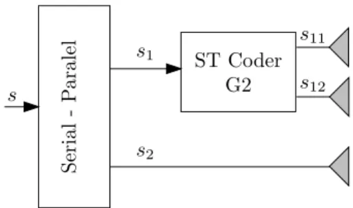
The hybrid MIMO scheme, which can provide both gains, was proposed in [8] and shown in Figure 2. Ir will be addressed in this paper as G2+1 and it consists of the transmission of the information into two layers. One layer is space-time block coded using the Alamouti scheme [9] (addressed in this
S
er
ial
-P
ar
al
el
s
s1
s2
s11
s12
ST Coder G2
Fig. 2. Hybrid MIMO Scheme with Diversity and Multiplex gain
paper as G2) and the other layer is non-space-time coded and operates in a co-channel way with the first layer following the V-BLAST idea. The transmitted signals can be organized in the equivalent matrix below
ΩHybrid=
s1 −s∗2
s2 s∗1
s3 s4
, (7)
C. Channel Estimation Techniques
Two channel estimation strategies are analyzed in the con-text of link adaptation. The first one, that will be addressed in this paper as “block-type channel estimation” (BTCE) , is proposed in [5] and uses all subcarriers to transmit known information in all transmit antennas at the same time. The known information corresponds to special training sequences that provide a way to estimate the channel in the time domain with low computational complexity.
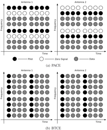
The second one, addressed in this paper as “pilot-assisted channel estimation” (PACE), is proposed in [6] and transmits pilot information in some equally spaced subcarriers in one transmit antenna while transmitting zeros the same location at the other transmit antennas and data in the remaining subcarriers.
Block type channel estimation is especially suitable for the case of high frequency selective channels in low mobility scenarios. Since it uses all the subcarriers to transmit know information, interpolation error is avoided. However, in high mobility scenarios the channel estimation needs to be per-formed more frequently.
On the other side, pilot-assisted channel estimation is espe-cially suitable for the case of low frequency selective channels with high mobility. Since it does not use all the subcarriers the estimation can be executed in every OFDM symbol (or at least in a more frequent rate than block type channel estimation) to track channel variations.
These two channel estimation techniques are illustrated in Figure 3 for the case of two transmit antennas.
(a) PACE
(b) BTCE
Fig. 3. Block Type Channel Estimation x Pilot Assisted Channel Estimation
−5 0 5 10 15
10−2 10−1
100 BLER for the V−Blast with 4 receive antennas
SNR (dB)
Block Error Rate
BTCE − 2/3 Efficiency BTCE − 7/8 Efficiency PACE − 5/8 Efficiency Perfect Channel knowledge
Fig. 4. Comparison of channel estimation strategies
channel variation, BTCE has an error floor at higher SNR values.
In the sequel we describe the process of link adaptation in MIMO-OFDM systems.
III. LINKADAPTATIONSTRATEGY
The link adaptation allows the system to adapt itself to the current state of the wireless mobile channel instead of being designed based on the worst case scenario. This approach provides a much more efficient use of the available resources. This is specially true for the case of a MIMO-OFDM system since it is very flexible and there are a great number of parameters which can be adapted as the usual modulation and coding schemes to MIMO scheme, antenna selection and even the channel estimation technique used.
In [7], an adaptive radio interface for MIMO systems is proposed in which a group of transmission parameters called Modulation, Coding and Antenna schemes (MCAS) is chosen according to the current channel condition to maximize the performance in terms of the normalized goodput (GP).
However, this study was evaluated for the case of flat fading channel with perfect channel state information available.
In a more realistic scenario, the channel estimation error can degrade the system performance and the link adaptation gain. Moreover, depending of the scenario (mobility, frequency selectivity, etc), block type channel estimation and pilot-assisted channel estimation may introduce a different quantity of redundancy to estimate the channel affecting, therefore, the normalized goodput (GP) achieved.
The normalized goodput is defined as
GP =GPmax·(1−BLER), (8)
where the maximum goodput, GPmax, corresponds to the
number of data bits sent per channel use. That is, for a MIMO-OFDM system withNF F T subcarriers, a cyclic prefix ofNCP
samples and 8 CRC bits for every 120 data bits, the maximum normalized goodput is given by
GPmax=120
128·
NF F T
NF F T +N CP ·
S·CE (9)
whereSis the product of the number of symbols per channel of each MIMO structure and the number of bits per constella-tion point of the modulaconstella-tion, and CE is the efficiency of the
channel estimation technique.
Next Section illustrates the results obtained by simulation for some tested scenarios.
IV. SIMULATIONRESULTS
The simulation was carried out for a MIMO-OFDM system with 1024 subcarriers and a cyclic prefix with 20 samples. The payload was chosen to be 128 bits (120 data bits + 8 bits for error detection using cyclic redundancy check - CRC) because it is close to real systems (144 bits for EDGE) and there is an integer number of payloads for each OFDM symbol. The number of pilot subcarriers in pilot assisted channel estimation is 128, which corresponds to1/8of the available subcarriers. However, when one antenna sends pilot data at one subcarrier to estimate the channel, all other antennas must send zero signal (see Figure 3). That is, pilot assisted channel estimation has an efficiency of 5/8 in our case with three transmit antennas.
Therefore, we change the interval between OFDM pilot symbols in block type channel estimation in such a way that the redundancy introduced by both techniques is very similar (one OFDM estimation symbol for each group of three OFDM data symbols resulting in an efficiency of3/4).
TABLE I
MAXIMUMNORMALIZEDGOODPUT FOR EACHMIMO SCHEME WITHOUT
CHANNEL ESTIMATION OVERHEAD
Modulation MIMO Scheme
Max Normalized Goodput
GPmax (Bits/Tsymb)
4-PSK G3 0.91954
2-PSK G2+1 1.8391
2-PSK V-Blast 2.7586
4-PSK G2+1 3.6782
TABLE II
MAXIMUMNORMALIZEDGOODPUT FOR EACHMIMO SCHEME WITH BTCE
Modulation SchemeMIMO
Max Normalized Goodput
GPmax (Bits/Tsymb)
4-PSK G3 0.6897
2-PSK G2+1 1.3793
2-PSK V-Blast 2.06897
4-PSK G2+1 2.7586
TABLE III
MAXIMUMNORMALIZEDGOODPUT FOR EACHMIMO SCHEME WITH PACE
Modulation SchemeMIMO
Max Normalized Goodput
GPmax (Bits/Tsymb)
4-PSK G3 0.5747
2-PSK G2+1 1.1494
2-PSK V-Blast 1.7241
4-PSK G2+1 2.2989
The channel used is the COST259 TU with Doppler fre-quencies of 100Hz (45Km/h when the carrier frequency is 2.4GHz) and 222.22Hz (100Km/h when the carrier frequency is 2.4GHz).
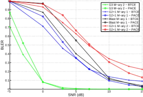
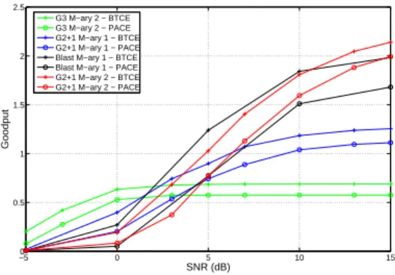
In Figures 5, 7, 9 and 11 it is possible to see that for low SNR values, the block type channel estimation achieves a lower block error ratio than pilot assisted channel estimation (except for the G3 scheme with a Doppler frequency of 222.22Hz1). However, channel variation introduces an error floor in the BTCE and PACE achieves better values of BLER for higher SNR values than BTCE, because of its better channel tracking capability. This behavior can be seen in the BLER curves for three and four receive antennas.
However, when the redundancy is also considered, that is, we use the metric of goodput, it can be seen that BTCE per-forms better than PACE, for the case of a Doppler frequency of 100Hz, at all the simulated SNR values. On the other side, for a Doppler frequency of 222.22Hz there is crossing between the channel estimation strategies performance in terms of goodput. This reinforces the idea that the goodput is a better metric to evaluate the channel estimation strategy than only the BLER. Therefore, none of the tested channel estimation techniques resulted in the highest goodput for all tested scenarios.
How-1This degradation in the G3 scheme performance is caused by the fact that
when BTCE is used, for every three OFDM data symbols we sent one training symbol for channel estimation. This means that while the G3 scheme needs the channel to be static for at least8OFDM symbols, when BTCE is used
this restriction changes to at least14OFDM symbols.
−50 0 5 10 15 20 0.1
0.2 0.3 0.4 0.5 0.6 0.7 0.8 0.9 1
SNR (dB)
BLER
G3 M−ary 2 − BTCE G3 M−ary 2 − PACE G2+1 M−ary 1 − BTCE G2+1 M−ary 1 − PACE Blast M−ary 1 − BTCE Blast M−ary 1 − PACE G2+1 M−ary 2 − BTCE G2+1 M−ary 2 − PACE
Fig. 5. Block Error Ratio for 3 receive antennas - Doppler Frequency of 100Hz
−50 0 5 10 15 20 0.2
0.4 0.6 0.8 1 1.2 1.4 1.6 1.8
SNR (dB)
Goodput
G3 M−ary 2 − BTCE G3 M−ary 2 − PACE G2+1 M−ary 1 − BTCE G2+1 M−ary 1 − PACE Blast M−ary 1 − BTCE Blast M−ary 1 − PACE G2+1 M−ary 2 − BTCE G2+1 M−ary 2 − PACE
Fig. 6. Goodput for 3 receive antennas - Doppler Frequency of 100Hz
−50 0 5 10 15
0.1 0.2 0.3 0.4 0.5 0.6 0.7 0.8 0.9 1
SNR (dB)
BLER
G3 M−ary 2 − BTCE G3 M−ary 2 − PACE G2+1 M−ary 1 − BTCE G2+1 M−ary 1 − PACE Blast M−ary 1 − BTCE Blast M−ary 1 − PACE G2+1 M−ary 2 − BTCE G2+1 M−ary 2 − PACE
Fig. 7. Block Error Ratio for 4 receive antennas - Doppler Frequency of 100Hz
ever, it is possible to obtain curves of goodput versus SNR for different values of Doppler frequency so that we can choose not only the most suitable transmission scheme, in a similar way to what was done in [7], but also the most suitable channel estimation strategy.
V. CONCLUSIONS
−5 0 5 10 15 0
0.5 1 1.5 2 2.5
SNR (dB)
Goodput
G3 M−ary 2 − BTCE G3 M−ary 2 − PACE G2+1 M−ary 1 − BTCE G2+1 M−ary 1 − PACE Blast M−ary 1 − BTCE Blast M−ary 1 − PACE G2+1 M−ary 2 − BTCE G2+1 M−ary 2 − PACE
Fig. 8. Goodput for 4 receive antennas - Doppler Frequency of 100Hz
−5 0 5 10 15 20 0
0.1 0.2 0.3 0.4 0.5 0.6 0.7 0.8 0.9 1
SNR (dB)
BLER
G3 M−ary 2 − BTCE G3 M−ary 2 − PACE G2+1 M−ary 1 − BTCE G2+1 M−ary 1 − PACE Blast M−ary 1 − BTCE Blast M−ary 1 − PACE G2+1 M−ary 2 − BTCE G2+1 M−ary 2 − PACE
Fig. 9. Block Error Ratio for 3 receive antennas - Doppler Frequency of 222.22Hz
−5 0 5 10 15 20 0
0.5 1 1.5
SNR (dB)
Goodput
G3 M−ary 2 − BTCE G3 M−ary 2 − PACE G2+1 M−ary 1 − BTCE G2+1 M−ary 1 − PACE Blast M−ary 1 − BTCE Blast M−ary 1 − PACE G2+1 M−ary 2 − BTCE G2+1 M−ary 2 − PACE
Fig. 10. Goodput for 3 receive antennas - Doppler Frequency of 222.22Hz
be adapted according to the situation. Two different channel estimation techniques were studied, the block type channel estimation [5] and the pilot-assisted channel estimation [6]; and different MIMO schemes were used to provide diversity gains, multiplexing gains, or a combination of both.
The results show it is possible to define groups of trans-mission parameters, including channel estimation, in a similar way to what is usually done in link adaptation for AWGN channels.
However, it is necessary to obtain a greater number of curves to allow link adaptation. That is, since we have con-sidered another dimension that affects the link adaptation, the
−50 0 5 10 15
0.1 0.2 0.3 0.4 0.5 0.6 0.7 0.8 0.9 1
SNR (dB)
BLER
G3 M−ary 2 − BTCE G3 M−ary 2 − PACE G2+1 M−ary 1 − BTCE G2+1 M−ary 1 − PACE Blast M−ary 1 − BTCE Blast M−ary 1 − PACE G2+1 M−ary 2 − BTCE G2+1 M−ary 2 − PACE
Fig. 11. Block Error Ratio for 4 receive antennas - Doppler Frequency of 222.22Hz
−50 0 5 10 15
0.2 0.4 0.6 0.8 1 1.2 1.4 1.6 1.8
SNR (dB)
Goodput
G3 M−ary 2 − BTCE G3 M−ary 2 − PACE G2+1 M−ary 1 − BTCE G2+1 M−ary 1 − PACE Blast M−ary 1 − BTCE Blast M−ary 1 − PACE G2+1 M−ary 2 − BTCE G2+1 M−ary 2 − PACE
Fig. 12. Goodput for 4 receive antennas - Doppler Frequency of 222.22Hz
Doppler frequency, then is is important to obtain curves of goodput versus SNR for different values of Doppler frequency. It must be noted that other transmition parameters can affect the channel estimation performance of the different strategies, such as the number of subcarriers, the channel model, etc..
A natural perspective for this work is the evaluation of scenarios with different power profiles and mobility, a greater number of transmit antennas, and the evaluation with MIMO schemes with space-frequency and space-time-frequency codes, instead of only space-time codes.
ACKNOWLEDGMENTS
D. C. Moreira is supported by FUNCAP (Fundac¸˜ao Cearense de Apoio ao Desenvolvimento Cient´ıfico e Tec-nol´ogico).
REFERENCES
[1] P. W. Wolniansky, G. J. Foschini, G. D. Golden, and R. A. Valenzuela, “V-blast: an architecture for realizing very high data rates over the rich-scattering wireless channel,” in Signals, Systems, and Electronics, 1998. ISSSE 98. 1998 URSI International Symposium on, 29 Sept. - 2 Oct. 1998, pp. 295 – 300.
[2] V. Tarokh, H. Jafarkhani, and A. R. Calderbank, “Space-time block codes from orthogonal designs,” IEEE Transactions on Information Theory, vol. 45, no. 5, pp. 1456 – 1467, July 1999.
[4] Correia L.M., “Wireless flexible personalised communications - cost 259 final report,” European Co-operation in Mobile Radio Resource, Tech. Rep., 2002.
[5] Y. Li, “Simplified channel estimation for OFDM systems with multiple transmit antennas,” IEEE Transactions on Wireless Communications, vol. 1, no. 1, pp. 67 – 75, January 2002.
[6] Y. Qiao, S. Yu, P. Su, and L. Zhang, “Research on an iterative algorithm of LS channel estimation in MIMO OFDM systems,” IEEE Transactions on Broadcasting, vol. 51, no. 1, pp. 149 – 153, March 2005.
[7] W. C. Freitas Jr., F. R. P. Cavalcanti, A. L. F. de Almeida, and R. Lopes, “Exploiting dimensions of the mimo wireless channel: multidimensional
link adaptation,” in Vehicular Technology Conference, 2005. VTC 2005-Spring. 2005 IEEE 61st, vol. 2, 30 May-1 June 2005, pp. 924 – 928. [8] W. C. Freitas Jr., A. L. F. de Almeida, F. R. P. Cavalcanti, and J. C. M.
Mota, “Performance of mimo antenna systems with hybrids of transmit diversity and spatial multiplexing using soft-output decoding,” in Lecture Notes in Computer Science, Springer-Verlag Heidelberg, vol. 3124, August 2004, pp. 28–37.