FILTERED
DELAY-SUBSPACE APPROACH FOR PILOT ASSISTED
CHANNEL ESTIMATION
IN
OFDM SYSTEMS
Rut
F.
Vigelis*, Darlan
C. Moreira*, J. C.
M.
Mota
and
Charles C. Cavalcante
Wireless Telecomm. Research Group (GTEL), Federal UniversityofCear.a, Fortaleza-CE, Brazil
{rfvigelis,darlan, mota,charles}@dgtel.ufc.br
ABSTRACT
In thispaper we propose a pilot-based OFDM channel
es-timator based onthe combination oflow-pass filtering and delay-subspace projection. The proposed estimator, which we abbreviate ST-LP, is robust in thesense it doesnot re-quire prior statistical knowledge of the channel. The only assumptions are the least-square (LS) estimates have lim-itedspectrumand the channel follows the tapped delay line (TDL) model, whicharecommonly taken in practice. Since it is desirable slow delay variations operability acceptance,
the delay-subspace is tracked by a subspace tracking (ST) algorithm. The ST-LP estimator can be implemented by
two filtering structures, which provide a trade-off between accuracyandcomplexity. Simulation results confirm the su-perior performance of the ST-LP estimator when compared
tomethods already reported in the literature.
1. INTRODUCTION
To achieve high data rates in orthogonal frequency divi-sion multicarrier modulation (OFDM) [1] it is mandatory
to employ multilevel modulation with nonconstant ampli-tude, such as 16-QAM. For efficient coherent demodula-tion, it isnecessary anaccuratechannel estimation method capable totrack the variations of the fading channel. Fur-thermore, the performance ofmanydiversity decoding tech-niques depends heavily on good channel estimates. In the works [2, 3], it is derived a minimum mean-square error (MMSE) channel estimator based on pilot symbols using Wiener-typefilters. The disadvantage of theoptimum
de-sign of these filters is the required knowledge of the channel statistics, whichare usually unknown at the receiver. This problem is avoided in the estimatorwe propose.
With theuseofacombpilot pattern arrangement [4, 5], wepropose achannel estimator basedontheapplication of subspace projection and low-pass filtering. Observing that thepilot subcarrier least-square (LS) estimates have limited
spectrum, wethen apply a low-pass filter that results ina significant decreasing of noise level. Inthepilot subcarrier
spectrumregion that isnotaffectedby the filter,partof the noise is discarded by projection onto the delay-subspace. From the parametric channel model, we have derived the delay-subspace [6]. The slow delay-subspace variations are
*The authors thank the financial support received by "Fun-dacao Cearense de Apoio ao Desenvolvimento Cientifico e Tec-nol6gico" -FUNCAP.
trackedbythesubspace tracking algorithm presentedin[7].
The proposed estimator is robust in the sense it is required a limited Doppler spectrum and delays ofslow variations and these assumptions are commonlyobserved in practice.
As we will present in the paper, the estimator can be im-plemented by meansoftwoforms. Thefirstone gives more accurate estimatesand presentshigher computational com-plexity. The later has inferior performance and lower
com-putational complexity. As verified bycomputersimulation,
theproposedestimatorgives much more accurate estimates w.r.t. totheLS channel estimator.
The restofthe paper is organized asfollows. InSection
2, we describe the OFDM system and the channel model we have taken into consideration. Section 3 exposes the
development oftheproposedestimators. InSection4, some computer simulation results and theeffective performance ofthe proposed estimator are shown. The paper ends in
Section 5 with our conclusions and perspectives.
2. CONSIDERED MODELS
2.1. OFDM System Model
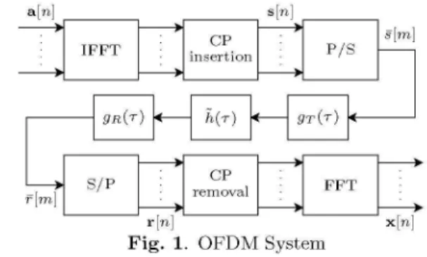
Fig. 1 shows the base-band model ofanOFDM system.
ar[m]
removlTr[n] x[n]
Fig. 1. OFDM System
Let
a[n]
=(a[n, 0], ., a[n,
N-1])T
be the vector con-taining the frequency domainsymbols allocated at theN,
subcarriers ofthe nth OFDM symbol. The transmitted
OFDM symbolisconstituted ofthe time domain versionof
a[n]
(obtained
by a normalizedIDFT)
added ofits cyclic prefix. Let Fbe the Fourier matrixof(k, I)-entry
givenbyexp
(j27rkl/N).
The additionofthecyclicprefixisprovidedby
theapplication
of thematrixe
(INCP ),
thatcopies
vector of length
N,.
Hence, we have the following OFDM symbol oflengthN =Np
+N,:
s
[n]
IaFH
a[n],7(
ofelements s[rn, k]. Each vector
s[n]
is serialized, resultinginthetransmitted signals[m] =
s[LmTNj,
(m)N],
whereLi1
and (-)N arethefloor and module operator, respectively.Let h[m,1] be the discrete time base-band channel
im-pulse response. In order to avoid interference between dif-ferent OFDM symbols,we assumethat the maximum chan-nel delay L satisfies L <
Ncp
+ 1. With a white andcir-cularly symmetric additive Gaussian noise r1[m] at the re-ceiver, the received signalis givenby
L-1
-r[m] = Z h[m, I]s[m- 1]+
r1[m].
1=0(2)
We obtain the received OFDM
symbol by
serial-to-parallel conversion of
Tr[m],
which gives thevec-tor
r[n]
= (7r[nN],
. .., r[nN,
+N,-1])T
. The receivedOFDM symbol is demodulated bythe removalofthecyclic prefix and the application ofa normalized DFT. Further,
we assume that e-1 =
(ON,X
NlP)INJ
is the matrixre-sponsible by discardingthe cyclic prefix. Thus, thevector
containing thesignalat the subcarriers isgivenby
x[n]
= ,1F
@-lr[n]
(3)
The signal at the subcarriers can be written as
x[n]
=diag(a[n])H[n]
+u[n]
+z[n],
(4)
where
H[n]
isthe channel responseatthefrequency
domain,u[n]
isthe intercarrierinterference(ICI),
z[n]
= ,-Frj[n]
is the noise at the frequency domain anddiag(.)
gives adiagonalmatrix formedwith the elements ofthe argument inthediagonal.
Defining the vector
h[m]
=(h[m,
0],
. ..,h[m,
L-1])T
andho
[im]
a version ofh[m]
trailed by N -L zeros, aftersomecalculations, we can write
H (n+1)N-1 [
H[n]
=Nm
EhN[T]N
,m=nN+N,p
(5)
i.e.,
theN,
1 vectorH[rn]
is thefrequency
domain versionofthe time averageover
N,
consecutivechannel realizations. If the channel do not vary intime, it meansho
=ho
[im]
for all m, then we haveh[n]
=fho,
and in thiscasetheICI istotalysupressed, i.e.,
u[n]
=0.2.2. Channel Model
We consider here the
tapped
delay
li'ne(TDL)
channel model[8].
The base-band representationofthe timevaryingchannelimpulse response is givenby
K-1
h
(t, T)
=E-Yk
(t)
6(T -T)
'(6)
k=O
where -Yk
(t)
andTk arethetime-varyingcomplexamplitude
and the delay ofthe kth path, respectively. In
h(t,T)
wehave not included the modulate filter gT(T) at the trans-mitter and the matched filter gR(T) at the receiver. The delayTk isconsidered almost constant, varyingslowlywith time. The complex amplitude
-yk(t)
is a wide sensesta-tionary (WSS) process w.r.t. time. For different k's, the
realizations of -Yk(t) areindependent. We assume that each
-Yk
(t)
has thesamenormalized correlationfunction,
accord-ing
torYk
(At) =E{'-Yk
(t +At)>Yk*
(t)}p(Tk)rt(At).
(7)Consideringthe channelobeysthe Jakes' model
[9],
wehavert(At)
=Jo(2wfdAt),
p(T) =
exp(-T/Tmax),
(8)
(9)
where Jo is the zero-order Bessel function ofthefirst kind,
and Tmax is the maximumdelay spread ofthe channel. The normalizedspectral density of -Yk(t) is limited to the maxi-mumDoppler frequency fd and is given by
I 1 I{ for
If
<fd'
Pj(f)
=d0
1 (ffd)fe
Lu, otherwise.
(10)
The overall base-band channelimpulseresponse is given
by
h(t,T)
=g(T) *h(t,T),
whereg(T)
=gT(T) *gR(T)
is the composite impulse response ofthe modulate and matchedfilters. These filters are designed toobey the Nyquist cri-terion. Generally g(T) is a raised-cosine with roll-off a.
Adopting the sampling period T, we have
K-1
h[,m, I]
=h(,mT, IT)
=Ykc(,mT)g(IT-Tk-7)
(11)
k=O
whereT0wasinserted in order to make
h[m,
1]
causal. Sinceg(T)
0forsufficiently
large
T,we canconsiderh[m, 1]
0for Idifferent of{0,. .. , L
-1}.
Wecanwrite(12)
where
h[m]
has Ithelementequaltoh[m, 1],
the matrixG,
hasg(lT-
Tk-)
as its(l,
k)th
entry, and -yk(mT)
is thekth element of
y[m].
h[m], G,
andAy[m]
have dimensions Lx1, LxKand Kx1, respectively. LetGo
be the matrixGr
trailed by N -L null rows such that we can writeho[m]
=Goy[m].
FromEq.(5),
we then have(n+1)N-1
HC[n]
= nFGNE[N])
m=nN+N,p
where
W,
=JFG,
r =diag(
(To),
....,/P(TK
)),
and
aT[m]
=r-1
(
N7
-[Am])
. We have insertedr in order that
E{a[n]aH[n]}
=1. Sinceg(T)
satisfies theNyquist criterion, the matrix
Wr
ofdimensionNC XKhas elements given approximately by(such
error is dueto the truncationerror)
(W,)k1k2
exp -j 27rki(Tk2° )j)
(14)
h[,m]
=G,-y[,m],
d[n,O]
d[n,O]
I *
Co-d[n,Ko -1] d[n,Ko
E
1....
1] UH[n,O]
H[n,N -1]
Table 1. ST Algorithm Initialization:
p; U
[0]
=o);
@[0]
=lp;
A[O]
= O; For each n:Z
[n]
UH[n-
1]H[n]
A[n] A[n- 1][n- 1]
+H[n]
zH
[n]
A
[n]
U[n]R[n]
(QR
factorization)
O
[n]
=U[n-1I] U[n]
(a)
givenbyB =
UAVH,
such that we canwriteH[n]
=Ud[n],
d[n]
= AVHa[n].
Withp=
rank(B)
<min(Np,
K),
we see thatd[n]
hasdi-mension p x 1. This fact will be explored in a tentative 1] of
computational
effortdecreasing. Alternatively,
the or-thogonal matrix U can be found by calculating the EVD ofEE{H[n]H
[n]
BE{f[n]HH[n]
}BHUA U.
(18)
Fig. 2. Filtering structureof(a) Form I and (b) FormII.
3. PROPOSED ESTIMATORS
Our system adopt a comb pilot pattern [4,
5],
where theNp
pilot symbols are allocated at equally spaced positions k=lNNp,
with I = 0,...,Np-1.
In order tofacili-tate the receiver design, the pilot symbols assume values
a[n,
INpINp]
=p[n,1]
C{-1,1}. The otherssymbols a[n, k]canbe taken from anyconstellation type.
In what follows, the barover matrixorvectorindicates we arejust considering, respectively, the rows or elements
of positions k=IN
Np,
for I =0,...,Np-
1. We havex[n]
=diag(a[n])H[rn]] +ii[nj +z[n].
(15)Since a[n] = p[n] = (p[n,0], ...,p[n,Np-1])T, the least
square (LS) estimative of
h[n]
issimply given byH[n]
=diag(p[n])x[n]
(16)=H
[n]
+diag
(p[n]) (-u[n]
+Yz[n]).
The LS estimator givespoorresults, since the ICIplusnoise termis still significant.
Its is possibletoobtainmoreaccurateestimativesof the channel by filteringthe LS estimate. Thefilteringstructure
abletomake fulluseof both time andfrequencycorrelation
ofthe channel isdepictedinFig. 2-(a). Suchfiltering struc-turewill be called Form I. The choice inthe MMSE sense ofoptimal matrix U and filter coefficients cl were derived
in [2]. Sincethis choice requires knowledge of thechannel
statistics, it is also derived a suboptimum filter where U consists ofa Fourier matrix F and the Ko = L (channel order) filters cl are sinc low-pass filters.
Inthispaperweexplorethe form ofEq. (13)that isnot
considered explicitly in [2]. Let the SVD of B =WV I be
Above we have used the fact that the elements of a
[n]
are independent. Since we just have access to the LS es-timate
H[n],
we calculate the EVD of the samplecorrela-- H
tionmatrixRH
[n]
n1H[i]H [i] and buildthe matrix
U[n]
withcolumns constituted of the eigenvectorsof the p largest eigenvalues ofRH[n].
In what follows, we assume p= K< Nc, although it ispossible tohave rank(B) <p.Wehave abetter estimate of
H[n]
given bythe projec-tion ofH[n]
onto thesubspace signal spanned byU[n],
as follows:d[n]
UH[n] Hi[n],
H[n]
=U[n]
d[n].
(19)The direct EVD calculation ofRH
[n]
requires a largeamount ofcomputational burden. To avoidthis, we make
useofthe
subspace
tracki'ng
(ST)
algorithm
[7]
summarized in Table 1. Althoughit is possible toestimate the rank ofB adaptively,for simplicity we assumethat we canfind at thereceiver side p= K that satisfiesp>rank(B).
In [6] it is proposed the subspace amplitude tracking
(SAT) algorithm, whose adaptation equations are
e[n]
=H[n] -U[n]d[n-
1]d[n]
d[n-1]
+M_UH[n]e[n]
(20) (21)
H[n] =U [n]d[n],
where theforgetting factor ,t satisfies 0 <,t < 2. After the substitution ofEq. (20) inEq. (21), we have
(22)
whose transfer function is c(z) =
,/(1
+ (u- 1)z-1).Ob-serve that c(z) is a low-pass filter. The SAT algorithm has the same filtering structure of Form I, with the exception
that now U is substitutedbyits time varyingversionU[n]
and the filters cl have all the same transfer function c(z).
Ho[n]
.>
H[n,N,,-1]
.>
uH
(b)
(17)
Due to variability of
U[n],
the estimateH[n]
can present somedegraded performance.If thefilters employed in Fig. 2-(a) are all the same, we can write
00
H[n]
= U ( ciU H[n])
i=O
UUH
(i
ciH[n]
),(23)
i=O
the channel length satisfies L <
Np
+ 1. In the SATal-gorithm, we adopted ,t = 0.6. The low-pass filters was
designed by selecting 41 values of sinc(2fdNTn) and the
application ofaChebyshevwindow with Fouriertransform sidelobe magnitude 20dB below the mainlobe magnitude
(see [10]). Obviouslyit is possible to have a more efficient
implementation ofthese filters.
where the ci's are the filter coefficients. Defining
Hf
[n]
= 0%ciH[n]
and usingU[n]
insteadofU, we haveH[n]
=U[n]
UH[n]
Hf[n].
-2
-4
(24)
The Eq.
(24)
definesthefilteringstructureshown in Fig.2-(b), where the LS estimate Hf
[n]
is first filtered and afterprojected onto the subspace of
U[n].
This filtering struc-turewill be called Form II. Compared tothe Form I with time-varyingU[n],
the Form II presents more accurate esti-mates. Thisfact isjustified bythe timevariability ofU[n].
On the other hand, the Form I has the advantage oflowercomputational complexity, since the filters are applied to
d[n],
whose dimension p is smaller than dimensionNp
ofH
[n].
The channel estimators we propose are based on Form I or II with the estimate U
[n]
in the place of U, andd[n]
been filtered by low-pass filters. These estimators will be called ST-LPthat standsfor subspace tracking low-passfilters. Sincethecomplex amplitudes-Yk(t)
have spec-trum limited to the maximum Doppler frequency fd, we can conclude thatd(w)
=E'
_.d[n]e-
` is limited to[-27fdNT,
27fdNT].
Sothe elimination ofnoise over therest ofthe spectrumof
d[n]
by the application ofthe dis-cretetimefiltersinc(2fdNTn)
will result in better estimatesof
H[n].
The Form IoftheST-LPestimatorpresents a little loss
of performance if compared to its respective Form II. As
seen, it is due to thevariability of
U[n].
In fact, this loss can be slightly alleviated with the use of low-pass filters of short impulse response. We can design these filters byany method. In order to avoid phase delay complications,
we adopted here the simpler one that consists of a sinc
filter truncation and posterior application ofa Chebyshev
window.
4. SIMULATION RESULTS
The OFDM system we have simulated employs a total
bandwidthof800kHz, with each OFDM symbol been con-stitutedof
N,
= 128 subcarriers andcyclic prefix of lengthN,p
= 15. The pilot symbols were allocated atNp
= 16equally spaced subcarriers, each one assuming the values {-1, 1}equally likely. The datasymbolsweretakenfroma
16-QAM
constellation. The channel realizations were sim-ulatedaccording tothe Jake's model givenby Eqs.(8)-(9).
The shaping filter
g(T)
was implemented bya sinc instead of a raised-cosine response. We used p = 4 delays. At each simulation run, thedelaysTk were independently anduniformly
selected in the interval[0, TNp- Tg],
where the time guard Tg = 4T was empirically chosen in order thatLS
A LP ST ST-LP-I
v ST-LP-II_ SAT-1 >< SAT-11 -6+;
m
u -8
U)
r -10
E
-12
0
z 14
- -\Xt ;-''''>arv eWut)(
-... ... ... .... ....
...
-16 ...
-18
--20
0 200 400 600 800 1000
n
Fig. 3. Normalized MSEcurvesfor aOFDMsystem oper-ating over SNR= 5dB for fd= 200 Hz.
-2
m
bo U)
z
-4
-6
-8
-14
LS
A LP
ST ST-LP-I
v ST-LP-II SAT-I >< SAT-11I
-16
-18_
0 200 400 600 800 1000
Fig. 4. Normalized MSE curvesfor a OFDMsystem
oper-atingover SNR= 5dB for fd= 500 Hz.
Firstly,weinvestigate the normalizedMSEbetween the channel and its estimate over the pilot subcarriers. For
SNR= 5dB, different curves of normalized MSE vs. num-berof processed symbolsareshown inFigs.3 and 4for
max-imumDopplerfrequency fd of200and 500Hz, respectively.
TheMSEwasestimatedbyaveraging over
104
OFDM sym-bols. Thedelay-subspace projection(ST label)
and the low-pass filtering(LP label)
performance are also consideredseparately. As expected, both techniques provideaccurate
estimates, with better results obtained bythe low-pass
fil-tering. The Form 11 type filtering structure given by the combination of low
pass-filtering
and delay-subspacepro-jection
outperform
considerably theLS estimator byupto14dB and 11 dBfor fd = 200and 500Hz, respectively. The
U.l. II
U l,
I\
-10
tor and presents almost constant MSE performance for a wide range of SNR values.
Improvements on the design of the low-pass filter is a natural continuation of this work. An adequate method that allows to have a good trade-off between performance and impulse response length is required since the filters should be as shortest as possible. Anotherdirection we aim togofurtheris the investigationofthe loss of performance
due to the variationofthe matrix
U[n].
We expect to findsuitable constraintsofsuch matrix in order to diminish the lossof performance. Finally, adeeper understandingofthe contribution of the ICI in theperformanceof the LP-based estimators isalso a research line we will pursuit.
-30
0 5 10 15 20
SNR(dB)
Fig. 5. Normalized MSE vs. SNR for different estimators.
less complex Form I presents inferior performance if com-pared to Form II. For effects of comparison, we see that the Form II of the SAT estimator slightly outperform its
respectiveForm I implementation.
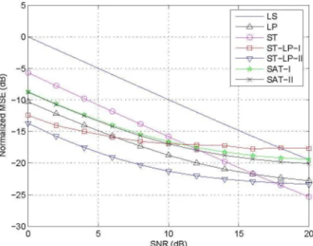
Fig. 5shows the MSE pilot subcarriers estimate
steady-state value versus SNR for different estimators operating
at fd = 200 Hz. These curves were obtained by averaging over 2 103 OFDM symbols. We can observe the linear performance of the ST estimator. Theoretically, the low-passfiltering based estimators should have the samelinear decreasing behavior. The observed saturation in such
esti-mators is due to filtering imperfections. Since in the SAT estimator thefiltering naturallyattenuatesall thespectrum
region, itsnormalized MSE curve tendsto saturate faster. Wecaneliminate such saturation effectsbybetterdesigning of thelow-pass filter. There is also the influence of the ICI, whose level doesnot change since the Doppler frequency is thesame. The real ICI contribution to the loss of perfor-mance still needs further investigation.
5. CONCLUSIONS AND PERSPECTIVES
Based on low-pass-filtering and delay-subspace projection, wedeveloped anefficient pilot based channel estimator for OFDM systems. The delay-subspace estimation is imple-mented by a subspace tracking algorithm capable totrack slowdelay variations. The estimator is robust inthesense it does notrequire knowledge of channel statistics. Wecan implement the estimator by two filtering structure forms. The first form provides better estimates and requires a higher computational complexity. The second has inferior performance but presents lower computational complexity. As shownby simulations, the proposed estimator, if imple-mented in FormI, outperforms significantly the LS
estima-6. REFERENCES
[1] J. A. C. Bingham, "Multicarrier modulation for data transmission: an idea whose time has come," IEEE Communications Magazine, vol. 28, no. 5, pp. 5-14, May 1990.
[2] Y. Li, L. J. Cimini Jr., N. R. Sollenberger, "Robust channel estimation for ofdm systems with rapid dis-persivefading channels," IEEE Transactions on
Com-munications, vol. 46, no. 7, pp. 902-915, July 1998. [3] Y. Li, "Pilot-symbol-aided channel estimation for ofdm
inwireless systems," IEEE Transactions on Vehicular Technology, vol. 49, no. 4, pp. 1207-1215, July 2000. [4] R. Negi, J. Cioffi, "Pilottoneselection for channel
esti-mation inamobile ofdm system," IEEE Transactions on ConsumerElectronics, vol. 44,no.3,pp.1122-1128, August 1998.
[5] S. Adireddy, L. Tong, H. Viswanathan, "Optimal
place-ment of training for frequency-selective block-fading channels," IEEE Transactions onInformation Theory, vol. 48, no. 8, pp. 2338- 2353, August 2002.
[6] 0. Simeone, Y. Bar-Ness, U. Spagnolini, "Pilot-based
channel estimation for ofdm systems by tracking the delay-subspace," IEEE Transactions on Wireless Com-munications, vol.3, no. 1, pp. 315-325, January 2004. [7] P. Strobach, "Low-rank adaptive filters," IEEE
Trans-actions on Signal Processing, vol. 44,no. 12,pp. 2932-2947, December 1996.
[8] R. Steele, MobileRadio Communications, IEEE Press, NewYork, 1992.
[9] W. C. Jakes, Microwave Mobile Communications, IEEE Press, New York, 1974.
[10] A. V. Oppenheim, R. W. Schafer, J. R. Buck, Discrete-Time Signal Processing, Prentice Hall, 2nd edition, 1999.
m bo
Ul)
z
LS LP ST ST-LP-I ST-LP-II SAT-I SAT-II