Abstract—The biomechanical data derived from the standard tensile testing machines may not be able to show the relative motion of the graft limbs. This paper uses a digital video recording system to determine the relative motion of a looped tendon graft. Bovine common digital extensor tendon was used to create the looped graft and then the graft was passed through a tunnel in a foam block and fixed with an interference screw. The structure then was mounted in a testing machine and the tendon limbs were speckled just moments before test. The specimen was then loaded to failure at a rate of 20 mm/min. The load-displacement data of the graft structure was evaluated using the tensile test machine while the relative motion of the individual graft limbs was measured by capturing the movements of the tendon speckles by the camera. A relative motion was monitored between the two limbs of the loop tendon graft. The relative motion between the loop limbs up to the point of the graft failure was 0.412 mm.
Index Terms—relative motion, tendon limb, video recording,
mechanical testing
I. INTRODUCTION
CCURATE measurement of the biomechanical properties of tendon grafts has significant implications in the surgical repair of anterior cruciate ligament (ACL) injuries [1]. Tensile testing is one of the most extensively used methods to measure the biomechanical properties of a tendon graft structure. The tendon consists of numerous collagen fibrils, each with very different mechanical properties. The mechanical behaviour of the tendon is complex and difficult to model [2]. The biomechanical data derived from the standard tensile testing machines may not entirely consider the parameters needed to determine the mechanical properties of a multiple graft structure and its individual limbs [3], [4].
In an effort to develop a more accurate method for measuring the mechanical properties of tendon, the investigation of alternate technologies has led to the use of Manuscript received January 15, 2014; revised March 25, 2014. All of the authors have no financial relationship to any private companies and organizations.
Jiayu Li is with the School of Design and Engineering, Brunel University West London, UK
Bin Wang is with the School of Design and Engineering, Brunel University West London, UK
Mohammad Alrashidi is with the Public Authority of Applied Education and Training, College of Technological Studies, Manufacturing Engineering Technology, Kuwait
Mahmoud Chizari is with the School of Mechanical Engineering, Sharif University of Technology, Tehran, Iran
Mahmoud Chizari is with Orthopaedic Learning and Research Center at Brunel University West London, UK, (corresponding author: Mahmoud Chizari. Phone: +447886454320; e-mail: mahmoudchizari@yahoo.com)
digital cameras. This method has been used to study the mechanical properties of biological soft tissues such as tendons [5].
The technique uses the captured video of the speckled object by a single solid state video camera, to represent the states of the object before and after deformation, or displacement field of the specimen. The testing specimen is mounted onto a loading frame and speckle patterns are acquired at various loading conditions [1], [2]. Parallel to the tensile test machine, the camera method provides additional information to assess the relative motion of the tendon limbs, which would not otherwise be possible with the standard test machine alone.
The aim of this study is to measure the mechanical properties of a looped tendon graft and examine the relative motion of its individual limbs using a combined tensile test machine with a camera method.
II. MATERIAL AND METHODS
A. Experimental setup
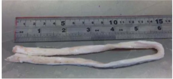
In this study the in vitro mechanical properties of the looped bovine common extensor tendon constructs was determined. The bovine tendon graft can be substituted for the human tendon graft in the experiments [6]. The harvested tendons were cleared of adherent muscle fibers and surrounding soft tissues. The tendons were frozen at -20°C in sealed plastic bags for no longer than three months. These preservation procedures have been shown not to affect the mechanical properties of tendon [7]. On the day of testing, the tendon samples were thawed to room temperature for 2 hours [8]. The specimen was kept moist with pure water during specimen preparation, and biomechanical testing. The specimen cut into 320 mm length to construct a 160 mm loop length tendon graft as shown in Fig 1. Tendon was doubled and then the diameter of the tendon was measured using a standard graft measuring scale. The diameter of all of the looped specimens was kept at 7 mm.
Fig 1. Bovine common extensor tendon specimen was prepared for the experimental test
Motion Investigation of a Tendon Graft’s Limbs
using Video Tracing Measurement
Jiayu Li, Bin Wang, Mohammad Alrashidi, Mahmoud Chizari
A
Proceedings of the World Congress on Engineering 2014 Vol I, WCE 2014, July 2 - 4, 2014, London, U.K.
ISBN: 978-988-19252-7-5
ISSN: 2078-0958 (Print); ISSN: 2078-0966 (Online)
Fig 2. The specimen was fixed with a metallic round-head interference screw(Arthrex Inc, Naples, FL) into the foam block
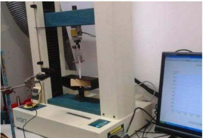
Synthetic solid sawbones foam block (Pacific Research Laboratories, Malmo, Sweden) with a density of 0.32 g/cc (20 pcf) was used as a bone model. A tunnel matching the graft diameter (7 mm) was drilled through appropriate location of the foam block and the debris was cleaned carefully from the tunnel. To get rid of any side effect on the foam block, the tunnel was drilled about 15 mm away from the edges of the foam block. Using a loop suture, the graft was passed through the tunnel until a 30 mm gauge length was achieved. The graft was fixed with a 7 mm metallic round-head interference screw (Arthrex, Naples, FL) (Fig 2). The loop potion of the tendon was hanged using a metal bare on the crosshead of testing machine while the sawbones block was secured using a custom-made rig at the testing machine. A Hounsfield (Tinius Olsen, UK) testing machine was used to carry out the experimental evaluation of this study (Fig 3).
B. Biomechanical testing
After mounting the specimen into the testing machine, the camera was installed in front of the specimen. The position of the camera in relation to the tensile machine is shown in Fig 3. A Logitech C920 camera (Logitech International, SA) was used for the video recording of the test and to capture the movement of the individual tendons. In order to generate high-contrast black and white speckles on the tendon surface, a marker pen was used to spread points on the specimen just moments before the load was applied, Fig 4a. An accurate scale was attached near the specimen to be utilized for calibration of the displacements capture by the camera, Fig 4b.
To start the tensile loading a pre load of 5 N was applied to make sure the tendon is not curved. The constructs was loaded to failure at a rate of 20 mm/min [7]. Failure was defined as tendon rupture or graft slippage.
After the test, the recorded video by the Logitech C920 camera was analysed in Tracker software (Open Source Physics, OSP). The Tracker is a video analysis tool which allows users to model and analyse the motion of objects in videos. Interference patterns and spectra can also be analysed with Tracker.
The measurements derived from the Tracker software was used to determine the displacement of the tendon limbs.
The tendon was kept moist whilst it was attached to the testing machine.
Fig 3. The mounted specimen in a Hounsfield testing machine. The camera was used to measure relative displacement of the tendon limbs. Experimental measurements were carried out using a camera and Tracker software.
(a) (b)
Fig 4. The camera was used to measure displacement of the markers. A surface marker (a) was used on the two limbs (b) of the doubled tendons.
C. Calibration
Before experimental testing of the real specimen, a calibration process was performed using the camera and testing machine. The calibration setup was performed to make sure the measurement of the camera is reliable. The camera was installed at a 70 mm distance from the testing rig. A measurement scale (Fig 4b) was then attached on to the rig, parallel to the camera lens. The camera was manually focused on the scale to make sure its picture was in focus. The calibration was performed on two different
speeds. The crosshead’s speed at the rate of 20 mm/min and
50 mm/min was measured by camera. Ten tests were performed for each group and then the speed of the crosshead was calculated as reported in Table I.
TABLE I
CALIBRATION RESULT AT SPEED RATES OF 20 AND 50 MM/MIN Machine speed 20mm/min 50mm/min
Test 01 19.56 47.39
Test 02 19.55 48.22
Test 03 19.23 48.56
Test 04 19.51 48.72
Test 05 19.44 47.81
Test 06 19.25 48.31
Test 07 19.49 49.27
Test 08 19.55 49.27
Test 09 19.35 49.27
Test 10 19.54 48.35
Average 19.45 48.52
Standard deviation 0.13 0.64 Proceedings of the World Congress on Engineering 2014 Vol I,
WCE 2014, July 2 - 4, 2014, London, U.K.
ISBN: 978-988-19252-7-5
ISSN: 2078-0958 (Print); ISSN: 2078-0966 (Online)
III. RESULTS
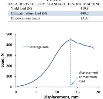
Following the load to failure test, the samples failed due to graft slippage, and all specimens passed through the 7 mm tunnel. No snap or breakage was monitored on the loop tendon or foam block. The load-displacement data was recorded and used to evaluate the mechanical properties of the graft, such as stress and strain of the tendon structure. The average load-displacement of the tendon graft specimens is illustrated in Fig 5. A summary of the mechanical properties of the tested specimens are reported in Table II.
By analysing the movement of speckles, incremental displacements could be obtained. At the test startup, the displacement was symmetry on the tendon limbs. With increasing the load, the displacement of the limbs gradually became different, Fig 6. The maximum difference between
the limbs’ displacements appeared at the failure position.
The maximum relative motion (mean value) between the loop limbs up to the point of graft failure was 0.412±0.01 mm (mean±SD). Tables III compares the result of the tested specimen obtained from the standard testing machine and camera method.
TABLE II
DATA DERIVED FROM STANDARD TESTING MACHINE
Yield load (N) 419.8
Ultimate failure load (N) 448.2
Displacement (mm) 13.37
Fig 5. Average load-displacement result of the tested tendon graft samples
Fig 6. Example of the contour of the vertical displacement at the moment of maximum load during the tensile loading of the tendon graft
TABLE III
COMPARING THE DISPLACEMENT RESULT (AT FAILURE) OBTAINED USING THE STANDARD TESTING MACHINE AND
CAMERA METHOD
Displacement, mm Limbs’ relative displacement Graft Limb A Limb B
Standard test 13.37 N/A N/A N/A Camera method 13.27 12.818 13.423 0.412
IV. DISCUSSION
The relative motion of tendon limbs of a double tendon graft for the application of ACL reconstruction when used in association with suspensory fixation may affect the mechanical behaviour of a tendon graft structure [3].
In this biomechanical study it has been observed that there is a relative motion between the two limbs of a looped tendon graft with suspensory fixation. This may be due to either unequal fixation force for both strands in the tunnel, non-uniform graft slippage or cut tendon fibers under loading. This discrepancy in displacement of the two limbs would result in differing values of strain for the individual limbs. However the relative motion is so minimal we can deduce that the biomechanical data derived for the whole tendon construct by the standard tensile testing machine accurately reflects the true biomechanical properties of the looped tendon graft in suspensory fixation.
There are a number of weaknesses in the current study. The camera method helped to evaluate the mechanical properties of the tendon graft. But the camera method captures the mechanical information of the tendon specimens from its speckled surface, and therefore the underlying bulk constitutive property of the tendon which may undergo a large deformation is not considered.
Also the camera method involves marking onto the specimen surface, in order to generate high-contrast black and white speckles. Differences in the application of such markers onto each of the tendon specimens may affect the quality of contrast and hence the displacement images generated.
Despite these inherent errors associated with the camera method, we believe that overall these will not significantly affect the relative motion of the loop limbs and hence does not limit the validity of over results and its clinical applicability. The camera method will show more detail about the mechanical properties of the graft limbs and in turn this may help clinicians to more accurately determine the strength of a multiple graft structure used in surgical reconstruction and subsequently improve fixation, e.g. the differing properties between a doubled and tripled tendon graft used for anatomical ACL reconstruction [1], [3].
V. CONCLUSION
In this study we have shown that camera method in conjunction with standard tensile testing machines enhances the mechanical testing of a tendon graft and provides additional information for assessing the mechanical properties of a looped tendon graft. Using the camera method we have found that there is a relative motion between the tendon limbs in a looped tendon graft with a suspensory fixation. However, the relative motion between the two limbs of the tendon graft is not significant. The Proceedings of the World Congress on Engineering 2014 Vol I,
WCE 2014, July 2 - 4, 2014, London, U.K.
ISBN: 978-988-19252-7-5
ISSN: 2078-0958 (Print); ISSN: 2078-0966 (Online)
model presented here may help to understand reasons for failure in grafts structure with multiple loops and suspensory fixation.
REFERENCES
[1] Mahmoud Chizari, Martyn Snow, William Cheung, Jamaluddin Mahmud, Bin Wang, Relative motion of tendon limbs in a loop tendon graft, Biomed. Eng. Appl. Basis Commun. 24 (5): 447, 2012, DOI: 10.4015/S1016237212500408
[2] William Cheung, Jamaluddin Mahmud, Martyn Snow, Bin Wang, Mahmoud Chizari, Slippery Motion between the Limbs of a Double Tendon Graft, Applied Mechanics and Materials, Vol 393 (2013), pp965-970, Main Theme: Advances in Manufacturing and Mechanical Engineering, Edited by: Wahyu Kuntjoro, Aidah Jumahat, Farrahshaida Mohd Salleh and Rosnadiah Bahsan, Trans Tech publication, Switzerland, DOI: 10.4028/www.scientific.net/AMM.393.965, Online since: Sep 2013 at www.scientific.net
[3] Martyn Snow, William Cheung, Jamaluddin Mahmud, Sam Evans, Catherine Holt, Bin Wang, Mahmoud Chizari, Mechanical assessment of 2 different methods of tripling hamstring tendons when using Suspensory fixation, Knee Surg Sports Traumatol Arthrosc. 2011, DOI: 10.1007/s00167-011-1619-5.
[4] Martyn Snow, William Cheung, Jamaluddin Mahmud, Sam Evans, Catherine Holt, Sanj Anand, Bin Wang, Mahmoud Chizari, Mechanical assessment of 2 different methods of tripling hamstring tendons when using suspensory fixation, 8th Biennial ISAKOS Congress, Rio de Janeiro, Brazil, May 15-19, 2011, (http://isakos.omnibooksonline.com/2011/data/papers/eposters/736.pd f)
[5] William Cheung,Jamaluddin Mahmud, Martyn Snow, Bin Wang, Mahmoud Chizari, Slippery motion between the limbs of a double
tendon graft (paper no 172#1569723277), International Conference
on Advances in Mechanical Engineering 2013 (ICAME2013), August
28-29, 2013, Malacca, Malaysia,
doi:10.4028/www.scientific.net/AMM.393.965 (http://www.scientific.net/AMM.393.965)
[6] Donahue TL, Gregersen C, Hull ML, Howell SM, Comparison of viscoelastic, structural, and material properties of double-looped anterior cruciate ligament grafts made from bovine digital extensor and human hamstring tendons. J Biomech Eng. 2001, 123(2):162-9. [7] Mahmoud Chizari, Bin Wang, Mel Barrett, Martyn Snow,
Biomechanical testing procedures in tendon graft reconstructive ACL surgery, Biomedical Engineering: Applications, Basis and Communications (BME), 22(5), 427–436, 2010; DOI: 10.4015/S1016237210002195
[8] Mahmoud Chizari, Bin Wang, Martyn Snow, Mel Barrett, Mechanical aspects of a single-bundle tibial interference screw fixation in a tendon graft ACL reconstruction, Biomedical Engineering: Applications, Basis and Communications (BME), 22(4): 271–278, 2010; DOI: 10.4015/S101623721000202X
Proceedings of the World Congress on Engineering 2014 Vol I, WCE 2014, July 2 - 4, 2014, London, U.K.
ISBN: 978-988-19252-7-5
ISSN: 2078-0958 (Print); ISSN: 2078-0966 (Online)