JOURNAL OF NANO- AND ELECTRONIC PHYSICS Р А А - А Р
Vol. 6 No 3, 03050(4pp) (2014) Том6№ 3, 03050(4cc) (2014)
The article was reported at the International Conference «The Advanced Technology, Equipment and Analytical Systems for Materials», Kursk, 13-14 May, 2014
2077-6772/2014/6(3)03050(4) 03050-1 2014 Sumy State University
The Use of GPUs for Solving the Computed Tomography Problem
A.E. Kovtanyuk1,2,*
1 Far Eastern Federal University, 8, Sukhanova Str., 690950 Vladivostok, Russia 2 Institute for Applied Mathematics, 7, Radio Str., 690041 Vladivostok, Russia
(Received 19 May 2014; revised manuscript received 03 July 2014; published online 15 July 2014)
Computed tomography (CT) is a widespread method used to study the internal structure of objects. The method has applications in medicine, industry and other fields of human activity. In particular, Electronic Imaging, as a species CT, can be used to restore the structure of nanosized objects.Accurate and rapid re-sults are in high demand in modern science. However, there are computational limitations that bound the possible usefulness of CT. On the other hand, the introduction of high-performance calculations using Graphics Processing Units (GPUs) provides improving quality and performance of computed tomography investigations. Moreover, parallel computing with GPUs gives significantly higher computation speeds when compared with (Central Processing Units) CPUs, because of architectural advantages of the former. In this paper a computed tomography method of recovering the image using parallel computations powered by NVIDIA CUDA technology is considered. The implementation of this approach significantly reduces the required time for solving the CT problem.
Keywords: Electronic imaging, Computed tomography, Parallel computing, Graphics processing units.
PACS numbers: 81.70.Tx, 02.30.Zz
* kovtanyuk.ae@dvfu.ru
1. INTRODUCTION
The main limitations on the development of numer-ical methods for solving complex problems are the huge amount of time required for calculations and the inac-cessibility and high cost of powerful computing cluster systems.
Despite the work of leading research organizations in the development of computing systems to improve the cost / benefit ratio of CT investigations, the demand for higher performance remains. In this case, an
inno-vative comprehensive development environment,
CUDA, created by NVIDIA provides a way forward [1]. The main new feature of CUDA is the option to send C, C++ and Fortran code directly to the Graphics Pro-cessing Units (GPUs), with no assembly language re-quired. Furthermore, this technology is available to anybody with graphics processing units compatible with CUDA.
A classic example of an unrealized task was the pro-ject of TechniScan Medical Systems [2]. The goal of the company was to recover a 3D image of the mammary glands of patients to diagnose diseases. The raw data for the image was obtained using ultrasonography. Howev-er, the use of CT methodology was not possible due to the high requirements on system resources, until NVID-IA released high performance GPUs, with CUDA.
The introduction of computed tomography (CT) has allowed researchers to reconstruct 2D and 3D represen-tations of the objects of analysis by stratified non-destructive influence. This method is widespread in med-icine, microscopy, petrophysics and geophysics. But the computational complexity of CT is still extremely high.
In CT the level of detail of an object depends on the step size of the grid chosen for scanning and calculat-ing. For two-dimensional images the computational complexity of the algorithm is equal to O(n3), where n is the dimension of the grid chosen. In medicine and
mi-croscopy the level of detail of a research object is crucial if it is to be used to make informed decisions. Thus, to obtain the two-dimensional internal structure of an
object with a diameter equal to 1 meter and with 10– 3
mm step size the order of the number of calculations is
1018, which is unacceptable for modern CPUs (Central
Processing Units), even taking into account multi-core systems. Note, that filtering noise caused by the scat-tering by various algorithm (See, for example, [3-5]) requires additional computational cost.
The implementation of computed tomography data processing on GPUs using NVIDIA CUDA provides a significant improvement to performance because of features of the algorithm. Another example of the suc-cessful introduction of computing with CUDA is the Procter & Gamble Company. Its research center modeled the efficiency of surface-active agents (surfac-tants). The researchers, by using two NVIDIA Tesla GPUs, archieved performance equal to the supercom-puter Cray XT3 with 128 processors, as well as the IBM BlueGene / L with 1024 processors [6]. In terms of economic advantages, it is important to understand that the energy consumption is proportional to the fourth power of the frequency of a processor [7]. Hence, if the clock frequency increases twofold, the electric energy consumption will raise 16 fold, as well as the heat released.
In recent years, the growth rate of the CPU fre-quency has dropped significantly. Therefore, there has been a new trend to increase the number of cores. In
terms of the number of cores, it is clear that GPU’s are far superior to CPU’s, for example AMD Opteron 6386S
A.E. KOVTANYUK J. NANO- ELECTRON. PHYS. 6, 03050 (2014)
03050-2 2. COMPUTATIONAL ALGORITHM FOR IMAGE
RECOVERY OF COMPUTED TOPOGRAPHY PROBLEMS
Let us consider in more detail the reconstruction al-gorithm of an object of research. The mathematical basis of the method was proposed by I. Radon in 1917 [8], which was based on the idea of recovering multivar-iate functions by its integral characteristics. However, the world's first X-ray tomography was demonstrated by G. Hounsfield [9] in 1972, since by that time there were X-ray machines performing a large number of high quality images, as well as a computer that could handle these images.
According to Radon’s methods, the structure of the object can be reconstructed from a series of parallel cross-sections with penetrating radiation. Suppose that we need to determine the density distribution of matter
1 2 ( , )
f x x in the cross section of the object. The object is
irradiated by a beams in the various directions. The reduction of the rays is proportional to the density of the matter. The residual intensity of the rays passing through the object along the straight line is fixed on the opposite side of the emitter. Suppose that as a result of irradiating at various angles, a set of integral projec-tions of the function f was obtained. The task of recon-structing the internal structure of the object is simpli-fied to the inversion of the Radon transform.
To restore the two-dimensional structure of the object under study from data of irradiation, we will use the parallel scheme of scanning. In this case, irradiation occurs at different angles of inclination of the studied object. For a fixed angle, radiation sources and detectors are located at the parallel lines (see Fig.1). For single angle, the number of radiographic lines is equal to 2q + 1. The number of radiographic angles is equal to p.
Fig. 1 – Parallel scanning scheme
As a result of scanning, a two dimensional array of data gj k, is obtained, where j1,...,p is an index
indi-cated the number of angle of irradiation, and ,...,
k q q is an index of radiographic line.
To solve the problem of computed tomography, we
apply the algorithmof convolutionandback projection, which consists of two steps.
Step 1. Calculating the convolution.
For all indices j1,…,p , and k–q,…,q to calcu-late the value of the convolution
, ( ( )) ,), , , .
q
j k b j i
i q
v h w h k i g k q q
Here, h is a distance between two parallel radiographic lines, wb is a filter, b is a given spectral width [5]. For example, b is equal to / h in the case, if this value is less than the number of angles of irradiations, and
2 2 2
( ( )) 1 (1 4( ) ).
b
w h k i h k i
Step 2. Calculating the back projection.
For each point of reconstruction we calculate discrete back projection
, , 11 2
( ) ((1 ) ),
p
j k j k j
f x u v uv
p
where
s
u k
h , sx1cosx2sin , j/p,
s 1
k k
h .
Some aspects of the implementation of the algo-rithm on GPUs are presented in the next section.
3. USING GRAPHICS PROCESSING UNITS FOR PARALLEL IMPLEMENTATION OF THE RE-CONSTRUCTION ALGORITHM
According to steps 1-2 of the reconstruction algo-rithm, the solving the CT problem reduces to a serial computation of matrixes vj k, and the function ( )f x on
a given grid with dimension NN. An important computational feature of the method is the independ-ence of computing vj k, for each index. Similarly, this
property holds for computing matrix fm n, , which is a
discrete representation of ( )f x on a given grid. Thus, the calculation of each element of the matrix vj k, and
the function ( )f x can be done independently. From the point of view of effective use of the CUDA technology, those arrays are distributed into groups. One of the simplest ways is a partition by the rows or columns. Hence, each row or column of the matrixes vj k, and
, m n
f is calculated by blocks. Grouped items are
trans-ferred for execution in the streaming multiprocessor CUDA (SM) GPU. The presence of many SMs allows processing blocks in parallel. Furthermore, each multi-processor includes extra scalar multi-processors (SPs), provid-ing additional parallelization. A feature of NVIDIA CUDA is the formation of blocks of tasks in the form of pools, called warp. The size of warp for modern GPUs that support CUDA is 32 threads. Tasks within a pool (warp) are executed in SIMD (Single Instruction Multi-ple Data) style, i.e. each thread inside the warp be able to carry out only one instruction. Thus, providing for each element of the matrixes vj k, and fm n, a sequence of
ena-THE USE OF GPUS FOR SOLVING… J. NANO- ELECTRON. PHYS. 6, 03050 (2014)
03050-3 bles the same operation for the group of the elements independently and in parallel, thereby improving per-formance. The number of available multiprocessors and scalar processors on the GPU plays a key role in estimat-ing the improved performance. An additional constraint is the amount of available memory, but additional frag-mentation processes can eliminate this concern.
Let us consider implementation of both steps of re-construction algorithm on GPUs for Cormack’s pha n-tom [10]. To test the program code the graphics nVidia GeForce GTX 660M (CUDA Capability 3.0) is used.
Implementing the first step.
Below are the results of testing the function that implements the first step of the algorithm for different block sizes (blockDim.x) and different number of blocks (gridDim.x) (see Table 1). Here, timeout is an error that occurred when it has exceeded the maximum computa-tion time, default value is 10 seconds; blocksize is an error generated in excess of the allowable number of threads per block.
Table 1 – Runtime of the first step of the algorithm depending
on the size and number of blocks
Test number blockDim.x gridDim.x Runtime 1 2 3 4 5 6 7 8 9 10 11 12 13 14 15 16 17 18 19 20 1 2 4 8 16 32 64 128 256 512 1024 2048 1024 1024 512 256 128 64 32 16 1 1 1 1 1 1 1 1 1 1 1 1 2 4 4 8 16 32 64 128 timeout 8.12078 4.26376 2.33119 1.30424 0.749946 0.441025 0.257105 0.180325 0.108049 0.054956 blocksize 0.0275024 0.0275249 0.0275238 0.0275835 0.0275793 0.0275684 0.0540881 0.100913
To optimize the program code, we introduced tem-porary variables to store some intermediate results of calculations that reduce runtime in 4,226 times. In ad-dition, to reduce the computation inside the function, all possible computations that do not depend on the indices were calculated on the host processor and placed in constant memory.
If amount of radiographic lines for single angle,
2q 1 is less than the maximum number of threads
per block, it is possible to compute the convolutions for each angle in a separate block. For this we perform the following optimization actions:
Radiographic data for single angle of irradiation must be multiples of 128 bits (see Fig. 2)
Taking into account thatsizeof the warpis 32,
de-termine the block size as 32s, where
32(s 1) 2q 1 32 .s
Before computing theconvolutionfor a singleangle
Fig. 2 – Scheme of storing data
of irradiation, radiographicdataare copiedfromglobal
memoryto shared memory.
Implementing the second step.
Computing the back projection is parallelized simi-larly to the first step, except that the use of shared memory is impossible, since the reconstruction of a sin-gle pixel of image requires radiographic data of all an-gles of irradiations.
Note, there is ability to recover the
three-dimensional structure of the object based on the two-dimensional reconstructions obtained for a set of cross sections using the considered algorithm.
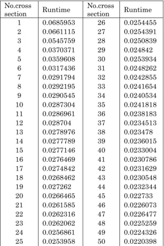
Here, in sequential computations, time spent on re-construction in a single cross-section decreases with increasing of the cross section No. (see Table 2).
Table 2 – Runtime of imaging of single cross section
No.cross
section Runtime
No.cross
section Runtime
A.E. KOVTANYUK J. NANO- ELECTRON. PHYS. 6, 03050 (2014)
03050-4 4. CONCLUSIONS
Thus, the development of computing technology on graphics processors can significantly reduce the compu-tational time required for image reconstruction of CT or Electronic Imaging problems. In addition, the described approach can effectively restore the image on a grid of a higher dimension, thereby improving the accuracy and quality of research in applied sciences. However, the
development of algorithms to efficiently use shared and global memory requires more attention.
ACKNOWLEDGEMENT
This work was supported by the Scientific Fund of the Far Eastern Federal University, by the Scientific Program "Far East", and by the Russian Foundation for Basic Research (project 13-01-00275).
REFERENCES
1. R. Farber, CUDA Application Design and Development
(Elsevier Inc.: 2011).
2. T. Valich, Tom’s Hardware US,
http://www.tomshardware.com/news/Nvidia-Tesla-Techniscan,5653.html (2008).
3. D.S. Anikonov, A.E. Kovtanyuk, I.V. Prokhorov,
Transport Equation and Tomography (Utrecht-Boston: VSP: 2002).
4. A.E. Kovtanyuk, I.V. Prokhorov, J. Inv. Ill-Posed Probl. 14 No 6, 609 (2006).
5. A.E. Kovtanyuk, I.V. Prokhorov, Num. Analysis Appl. 1
No 1, 46 (2008).
6. D. Sanders, E. Kandrot, CUDA by Example: An Introduc-tion to General-Purpose GPU Programming (New York: Addison-Wesley Publishiong: 2011).
7. A.V. Boreskov, A.A. Kharlamov, The basics of working with the CUDA technology (Moscow: DMK: 2010). 8. F. Natterer, The mathematics of computerized tomography