The use of three-dimensional cephalometric references
in dentoskeletal symmetry diagnosis
Olavo Cesar Lyra Porto1, Jairo Curado de Freitas2, Ana Helena Gonçalves de Alencar3, Carlos Estrela4
Objective: The aim of this study is to assess dentoskeletal symmetry in cone-beam computed tomography (CBCT) scans of Brazilian individuals with Angle Class I malocclusion. Material: A total of 47 patients (22 females and 25 males) aged between 11 and 16 years old (14 years) seen in a private radiology service (CIRO, Goiânia, GO, Brazil) were as-sessed. All CBCT scans were obtained from January, 2009 to December, 2010. Cephalometric measurements were taken by multiplanar reconstruction (axial, coronal and sagittal) using Vista Dent3DPro 2.0 (Dentsply GAC, New York, USA). Minimum, maximum, mean and standard deviation values were arranged in tables, and Student t-test was used to determine statistical significance (P < 0.05). Results: Data were homogeneous, and differences between the right and left sides were not significant. Conclusions: Cephalometric measurements of Brazilian individuals with Angle Class I malocclusion can be used to establish facial symmetry and three-dimensional standard references which might be useful for orthodontic and surgical planning.
Keywords:Facial asymmetry. Three-dimensional imaging. Cone-beam computed tomography.
How to cite this article: Porto OCL, Freitas JC, Alencar AHG, Estrela C. The use of three-dimensional cephalometric references in dentoskeletal symmetry di-agnosis. Dental Press J Orthod. 2014 Nov-Dec;19(6):78-85. DOI: http://dx.doi. org/10.1590/2176-9451.19.6.078-085.oar
Submitted: November 04, 2013 - Revised and accepted: April 02, 2014. » The authors report no commercial, proprietary or financial interest in the prod-ucts or companies described in this article.
Contact address: Carlos Estrela
Universidade Federal de Goiás, Departamento de Ciências Odontológicas, Praça Universitária, S/N – Setor Universitário
CEP: 74605-220 – Goiânia/GO — Brazil E-mail: [email protected]
1 PhD resident in Health Sciences, Federal University of Goiás (UFG). 2 Professor, Department of Orthodontics, Brazilian Dental Association (ABOR). 3 Professor, Department of Endodontics, UFG.
4 Full professor, Department of Endodontics, UFG. DOI: http://dx.doi.org/10.1590/2176-9451.19.6.078-085.oar
» Patients displayed in this article previously approved the use of their facial and intraoral photographs.
Objetivo: o objetivo deste estudo é avaliar a simetria dentoesqueléticas em imagens de tomografia computadorizada de feixe cônico (TCFC) de indivíduos brasileiros com má oclusão Classe I de Angle. Métodos: quarenta e sete pacientes (22 meninas e 25 meninos), com idades entre 11 e 16 anos (14 anos, em média), foram atendidos em um serviço de ra-diologia privado. Todas as imagens de TCFC foram adquiridas a partir de janeiro de 2009 a dezembro de 2010. Medições cefalométricas foram realizadas por reconstruções multiplanares (axial, coronal e sagital) usando o VistaDent 3D Pro 2.0 ( Dentsply GAC, Nova Iorque, EUA). O desvio-padrão mínimo, máximo e a média foram descritos em tabelas, e o teste
t de Student foi utilizado para definir significância estatística (p < 0,05). Resultados: os dados foram homogêneos e as diferenças entre os lados direito e esquerdo não foram significativas. Conclusões: as medidas cefalométricas de indiví-duos brasileiros com má oclusão Classe I de Angle podem ser usadas para definir a simetria facial e referências de padrão tridimensional, que podem ser úteis para o planejamento ortodôntico e cirúrgico.
INTRODUCTION
Assessing skeletal asymmetry by means of cepha-lometric and panoramic radiograph of individuals in need of orthodontic treatment is an ongoing chal-lenge that requires attention. Knowledge about cra-niofacial growth and growth direction, skeletal anat-omy, tooth position, tooth relationship with bone structures, and facial profile is essential for accurate
treatment planning.1
Cephalometry focuses on linear and angular dimen-sions established by bone, teeth and face measurements; and cephalometric indings aid diagnosis and help to es-tablish treatment strategies.
Dentists use lateral cephalogram to establish the cephalometric references of normal individuals with
a balanced face.2,3 Despite potential limitations such
as image distortion and superposition, posteroante-rior radiograph is useful for other types of assessment. Nevertheless, it is considered reliable for surgical and
orthodontic planning.4
Inaccurate image reading may be associated with superposition of anatomical structures and increased radiographic image distortion. Furthermore, correct management of patients during image acquisition is a risk factor that may afect quality. Two-dimensional ra-diographs are limited and might afect treatment
plan-ning and results negatively.4,5,6
The use of cone-beam computed tomography (CBCT) in Dentistry has raised several possibilities for planning, treatment and follow-up in a number of
spe-cialties.7-21 Farman and Scarfe16 reported that several
CBCT systems may be used to obtain reconstructions similar to conventional cephalometric scans. According
to these authors,16 CBCT diagnostic precision and
ef-icacy may be compared to conventional cephalometric imaging. Additionally, they also state that evidence-based selection criteria should be developed for CBCT use in Orthodontics.
Cephalometric analysis has been used to assess lin-ear and angular measurements of hard and sot tissues of the craniofacial complex, while CBCT scans have been
helpful in assessing facial asymmetry.24 New facial
ex-amination models may be developed by combining the use of conventional cephalometric references and
three-dimensional CBCT scans.25,26 This study assessed
den-toskeletal symmetry of Angle Class I patients by means of three-dimensional scans.
MATERIAL AND METHODS
Sample selection
Facial symmetry of a group of patients was deter-mined and resulted in a clinically symmetrical sample. Ater that, three-dimensional scans of 47 patients (22 females and 25 males) aged between 11 and 16 years old (14 years) were retrieved and further assessed. The following inclusion criteria were applied: Angle Class I malocclusion, crowding, absence of dental caries and apical or marginal periodontitis. Exclusion criteria were: Angle Class II or III malocclusion, absence of teeth, traumatic bone and tooth injury, and previous orthodontic treatment. This study was approved by the local Institutional Review Board (Federal University of Goiás, Brazil, # 296/2011).
Method used to determine facial symmetry
Patients’ digital frontal facial photographs were as-sessed by three specialists in Orthodontics. Facial sym-metry was determined according to visual inspection and facial photographs. Clinically symmetrical patients were selected for cephalometric measurements.
Image acquisition method
CBCT scans were acquired in a private radiology clinic (CIRO, Goiânia, GO, Brazil) using an i-CAT scanner (Imaging Sciences International, Hatield, PA, USA). Volumes were reconstructed according to the following exposure settings: 0.25-mm resolution, iso-metric voxel, 120 kVp, tube voltage, 3.8 mA current, exposure time of 40 seconds and ield of view of 13 cm. Images were acquired at 14-bit grey scale at a focal
dis-tance of 0.5 mm and 360o rotation.
Images were assessed by Xoran 3.1.62 sotware (Xo-ran Technologies, Ann Arbor, USA) in a workstation Intel Core® 2 Duo 1.86 Ghz-6300 processor (Intel Cor-poration, Santa Clara, USA), NVIDIA GeForce 6200 turbo cache video card (NVIDIA Corporation, Santa Clara, USA), EIZO - S2000 FlexScan monitor (1600 x 1200 pixels resolution) and Microsot Windows XP pro-fessional SP-2 operating system (Microsot Corp, Red-mond, USA). Ater reconstruction, data were stored in individual DICOM iles according to each patient.
Cephalometric measurements
3D Pro 2.00 (Dentsply GAC, New York, USA). A total of 17 cephalometric landmarks selected according to a speciic protocol for dentoskeletal symmetry assess-ment were identiied by a calibrated operator, who had more than ive years experience, and plotted by means of axial, coronal and sagittal multiplanar reconstruction (Table 1; Figs 1 and 2). Subsequently, reference planes
were determined (Tables 2 and 3) and the linear mea-surements were automatically calculated by the sot-ware (Table 3; Figs 4 and 5). Values were recorded in
a Microsot Oice Excel® 2010 spreadsheet. Image
up-grading and maximal magniication tools were used to ensure that all cephalometric landmarks were precisely plotted on each multiplanar reconstruction.
Table 1 - Cephalometric landmarks.
Cephalometric
landmark Cephalometric landmark description
Porion R (Po R) The most superior point of the right auditory meatus
Porion L (Po L) The most superior point of the left auditory meatus
Orbitale R (Or R) The lowest point on the right inferior orbital margin
Orbitale L (Or L) The lowest point on the left inferior orbital margin
Anterior nasal
spine (ANS) The lowest point of the maxillary anterior nasal spine
Posterior nasal spine (ENP)
The most posterior point of the maxillary posterior nasal spine
Capitulare R Center of the head of right mandible
Capitulare L Center of the head of left mandible
Condylion R
(Co R)
The most superior posterior point of the right mandibular
condyle
Condylion L
(Co L)
The most superior posterior point of the left mandibular
condyle
#16 The deepest point on the central fossa of right maxillary irst molar
#26 The deepest point on the central fossa of left maxillary irst molar
#36 Distobuccal cuspid tip of left mandibular irst molar
#46 Distobuccal cuspid tip of right mandibular irst molar
Gonion R (Go R) The mid-point on the posterior outline of the angle of the mandible on the right side
Gonion L (Go L) The mid-point on the posterior outline of the angle of the mandible on the left side
Gnathion (Gn) The most anterior inferior point on the mandibular symphysis.
Table 2 - Cephalometric measurements reference planes
Reference plane Plane description
Frankfort horizontal
plane (FHP) Line connecting right and left porion to left orbitale
Coronal plane (CP) Line connecting right and left porion, perpendicular to the Frankfort horizontal plane
Midsagittal plane (MSP)
Line connecting anterior and posterior nasal spines, perpendicular to the Frankfort horizontal plane
Maxillary horizontal
plane (MHP)
Line connecting anterior and posterior nasal spines,
perpendicular to the midsagittal plane
Mandibular plane
(MP) Line connecting right and left gonion to gnathion
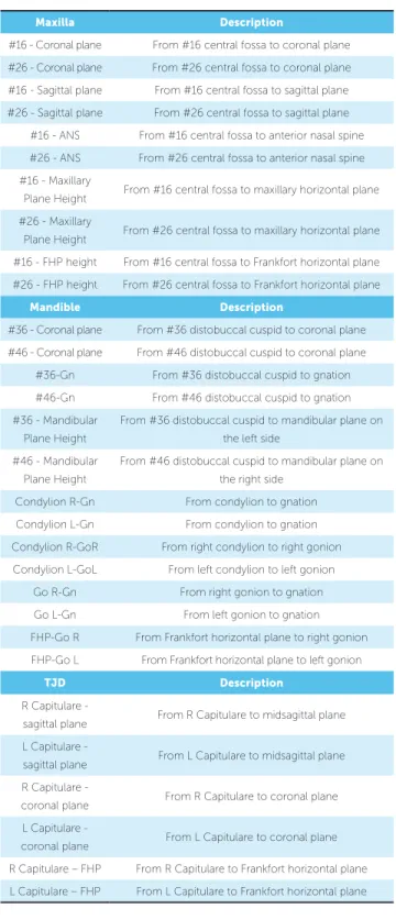
Table 3 - Cephalometric measurements.
Maxilla Description
#16 - Coronal plane From #16 central fossa to coronal plane
#26 - Coronal plane From #26 central fossa to coronal plane
#16 - Sagittal plane From #16 central fossa to sagittal plane
#26 - Sagittal plane From #26 central fossa to sagittal plane
#16 - ANS From #16 central fossa to anterior nasal spine
#26 - ANS From #26 central fossa to anterior nasal spine
#16 - Maxillary
Plane Height From #16 central fossa to maxillary horizontal plane
#26 - Maxillary
Plane Height From #26 central fossa to maxillary horizontal plane
#16 - FHP height From #16 central fossa to Frankfort horizontal plane
#26 - FHP height From #26 central fossa to Frankfort horizontal plane
Mandible Description
#36 - Coronal plane From #36 distobuccal cuspid to coronal plane
#46 - Coronal plane From #46 distobuccal cuspid to coronal plane
#36-Gn From #36 distobuccal cuspid to gnation
#46-Gn From #46 distobuccal cuspid to gnation
#36 - Mandibular
Plane Height
From #36 distobuccal cuspid to mandibular plane on
the left side
#46 - Mandibular
Plane Height
From #46 distobuccal cuspid to mandibular plane on
the right side
Condylion R-Gn From condylion to gnation
Condylion L-Gn From condylion to gnation
Condylion R-GoR From right condylion to right gonion
Condylion L-GoL From left condylion to left gonion
Go R-Gn From right gonion to gnation
Go L-Gn From left gonion to gnation
FHP-Go R From Frankfort horizontal plane to right gonion
FHP-Go L From Frankfort horizontal plane to left gonion
TJD Description
R Capitulare -
sagittal plane From R Capitulare to midsagittal plane
L Capitulare -
sagittal plane From L Capitulare to midsagittal plane
R Capitulare -
coronal plane From R Capitulare to coronal plane
L Capitulare -
coronal plane From L Capitulare to coronal plane
R Capitulare – FHP From R Capitulare to Frankfort horizontal plane
Figure 1 - 3D cephalometric module of VistaDent 3D Pro 2.00 software (Dentsply GAC, New York, USA). 3D reconstructions (A), Axial (B), coro-nal (C) and sagittal slices (D).
Figure 2 - Right porion cephalometric landmark (PoR) identified in the 3D
(A), axial (B), coronal (C) and sagittal (D) multiplanar reconstructions.
Figure 4 - Three-dimensional image of cephalometric measurements
be-tween #16, #26 and the midsagittal plane.
Figure 3 - Three-dimensional reconstructions of the reference planes:
Frankfort Horizontal Plane (red), Coronal Plane (blue), Midsagittal Plane (yel-low), Maxillary Plane (orange) and Mandibular (green).
Figure 5 - Three-dimensional image of cephalometric measurements from
Cephalometric
measurements
Minimal and maximum values (mm)
Mean and standard deviation
Minimal Maximum Minimal Maximum
Maxilla #16 #26 #16 #26 p
#16/26 - Coronal Plane 51.30 71.11 52.63 70.35 61.56 ± 4.47 61.22 ± 4.12 0.073
#16/26 - Sagittal Plane 19.96 26.47 19.56 26.51 23.33 ± 1.45 23.48 ± 1.51 0.453
#16/26 - ANS 38.60 51.74 38.36 51.37 44.75 ± 2.85 44.94 ± 2.91 0.240
#16/26 - MHP 15.10 25.69 14.61 27.44 20.56 ± 2.85 20.54 ± 2.79 0.348
#16/26 - FHP 31.97 49.21 31.32 47.82 40.36 ± 3.48 40.27 ± 3.45 0.610
Mandible #46 #36 #36 #46 p
#16/26 - Coronal Plane 50.72 71.27 52.21 69.05 61.62 ± 4.33 61.60 ± 4.59 0.964
#16/26 - Gn 45.24 59.05 44.79 57.05 49.68 ± 2.50 49.74 ± 2.85 0.716
#16/26 - Height-GoGn 22.12 30.77 21.84 31.40 25.81 ± 2.19 25.92 ± 1.99 0.587
Mandible Right Left Left Right p
Condylion-Gn 101.24 127.48 100.27 126.6 117.11 ± 4.74 117.42 ± 4.71 0.230
Condylion-Go 42.18 59.12 43.58 60.20 49.42 ± 3.33 49.84 ± 3.50 0.087
Go-Gn 76.45 92.85 77.61 90.4 84.51 ± 3.37 84.66 ± 3.44 0.569
FHP-Go 43.12 62.98 41.94 63.94 51.42 ± 4.23 51.88 ± 4.28 0.100
TMJ Right Left Left Right p
Capitulare - MSP 43.83 51.43 42.55 51.25 47.84 ± 1.90 47.29 ± 2.17 0.036
Capitulare - Coronal Plane 6.66 12.96 5.93 13.18 10.18 ± 1.37 9.45 ± 1.32 0.000
Capitulare - FHP 3.27 11.61 3.40 11.65 7.33 ± 1.99 7.31 ± 1.79 0.894
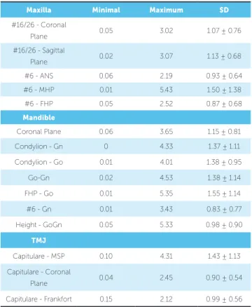
Table 5 - Means and standard deviation (SD) of differences between right and
left sides in Angle Class I patients (n = 47).
Table 4 - Means and standard deviation of cephalometric measurements obtained from Angle Class I patients (n = 47).
Maxilla Minimal Maximum SD
#16/26 - Coronal
Plane 0.05 3.02 1.07 ± 0.76
#16/26 - Sagittal
Plane 0.02 3.07 1.13 ± 0.68
#6 - ANS 0.06 2.19 0.93 ± 0.64
#6 - MHP 0.01 5.43 1.50 ± 1.38
#6 - FHP 0.05 2.52 0.87 ± 0.68
Mandible
Coronal Plane 0.06 3.65 1.15 ± 0.81
Condylion - Gn 0 4.33 1.37 ± 1.11
Condylion - Go 0.01 4.01 1.38 ± 0.95
Go-Gn 0.02 4.53 1.38 ± 1.14
FHP - Go 0.01 5.35 1.55 ± 1.14
#6 - Gn 0.01 3.43 0.83 ± 0.77
Height - GoGn 0.05 5.33 0.98 ± 0.90
TMJ
Capitulare - MSP 0.10 4.31 1.43 ± 1.13
Capitulare - Coronal
Plane 0.04 2.45 0.90 ± 0.54
Capitulare - Frankfort 0.15 2.12 0.99 ± 0.56
Statistical analysis
Mean and standard deviation of all cephalometric mea-surements were obtained. Cephalometric meamea-surements from both let and right sides and the diferences between them were recorded in two subsequent tables. Those dif-ferences were assessed by t-test for paired samples and Wil-coxon test. Data normality was assessed by Kolmogorov-Smirnov test. Values were signiicant at P < 0.05.
Diferences between measurements obtained on the let and right sides were recorded by descriptive statistics in Table 5 which shows minimal, maximum, mean and standard deviation values. All statistical anal-yses were performed by means of SPSS (20.0, SPSS Inc, Chicago, USA).
RESULTS
DISCUSSION
Facial harmony, an ancient esthetic concern of hu-man beings, was conirmed by facial photographs of Angle Class I Brazilian patients, despite diferences be-tween right and let cephalometric measurements.
Orthodontic treatment is planned based on the linear and angular measurements of the craniofacial complex. For decades, measurements were taken on the basis of two-dimensional images. Lateral and posteroanterior cephalograms as well as panoramic radiographs were of-ten used as complementary examination by specialized
dentists, mainly in Orthodontics.26,31-38 Measurements
are usually obtained on the basis of two-dimensional scans of three-dimensional structures.
CBCT has redeined cephalometric analysis.27-30,39
Methods may have to be adapted to CBCT risks and beneits, as well as to its three-dimensional scans so as to increase the accuracy of cephalometric measurements.
This study used VistaDent 3D Pro 2.00 (Dentsply GAC, Nova York, USA) which enables navigation in the axial, sagittal and coronal planes so as to take cepha-lometric measurements. Measurements taken on the basis of CBCT scans are more accurate and reliable due to better magniication and less distortion than
two-dimensional images.26,27,40-43
Three-dimensional cephalometric analyses were
car-ried out to establish reference values. Sievers et al.44
as-sessed 70 patients and used the index by Katsumata et al24
to measure asymmetry in Class I and II patients. The in-dex was calculated based on the distances from the cra-niometric landmarks to the midsagittal, coronal and axial planes. The midsagittal plane was established by sella, nasio and dent landmarks; whereas the axial plane was established by the sella and nasio landmarks and was per-pendicular to the midsagittal plane. Dent landmark was used to determine the coronal plane which was perpen-dicular to the other two planes. Angle Class II patients were not more asymmetrical than Class I patients.
In this study, landmarks and measurements were used to assess symmetry according to ive planes: midsagittal, coronal, Frankfort horizontal, maxillary and mandibular. These planes were used as reference for cephalometric measurements. The midsagittal plane was established by the anterior and posterior nasal spines and was perpen-dicular to the Frankfort horizontal plane according to a
model, which difers Katsumata et al.24 The coronal plane
connected the right and let porion and was perpendicular
to the Frankfort horizontal plane. There were signiicant diferences in Capitulare-MSP and Capitulare Coronal-Plane cephalometric measurements.
Using diferent methods to locate craniometric land-marks and three-dimensional cephalometric measure-ments afects the process of establishing reference values, which hinders comparison with results yielded by
pre-vious studies.24,27,44,45 Some studies have used algorithms
to demonstrate the use of three-dimensional cepha-lometry and to derive two-dimensional
cephalomet-ric references for three-dimensional evaluations.26,41,46
New cephalometric methods using three-dimensional
scans have been suggested.27,28,29 Cheung et al29
devel-oped a model of cephalometric analysis of dentofacial abnormalities and established new cephalometric
refer-ence values for Chinese adult patients. Cavalcanti et al30
assessed the accuracy of craniofacial bone and tissue measurements obtained by means of 3D computed to-mography (CT) and a volume technique using an inde-pendent workstation with graphic tools. The 3D-CT measurements proved accurate in assessing growth and
developmental changes. Takahashi et al3 assessed facial
skeletal structures using the vertical view of cephalo-metric lateral radiographs not only to establish the mean normality values for young Brazilians whose ancestors were white or Asian with normal occlusion, but also to assess the diferences between males and females and ethnic groups under study. Their results suggested that males and females from both ethnic groups presented diferences in some of the cephalometric measurements. Additionally, diferences between the two ethnic groups under study were also observed.
The reference values obtained in this study are com-plementary to other dentoskeletal symmetry indings, such as those provided by clinical and model analyses. Tooth size discrepancies may result in midline devia-tion which also leads to asymmetry. The Bolton discrep-ancy analysis of digital CBCT models has been used to
assess the efect of teeth on asymmetry. Tarazona et al47
assessed the reproducibility and reliability of the Bolton index when using digital CBCT models and digitized images of conventional models. Although both methods proved clinically acceptable, CBCT results were accurate
and reproducible. Sanders et al48 compared the degree of
and condyle asymmetries. The distances from the con-tact points of maxillary and mandibular central incisors to the midsagittal plane were measured together with linear and angular measurements so as to establish dentoskeletal asymmetry. These measurements were essential for the precise diagnosis of dentoskeletal symmetry.
Asymmetries may result in esthetic and functional deviations of variable intensity. Thus, using cephalom-etry to determine the severity of asymmcephalom-etry is an essen-tial tool in orthodontic planning. CBCT may be used for cephalometric analysis, but this three-dimensional tool exposes patients to radiation. Therefore, care should be taken to ensure the best cost-beneit
relation-ship between information and radiation dose,22,23 and
decisions should respect the ALARA principle (as-low-as-reasonably-achievable).
Further studies should be conducted to determine the clinical signiicance of diferences and standard de-viations. The faces of subjects included in our study were symmetrical, but cephalometric measurements re-vealed diferences between the let and right sides as well as statistical diferences in two cephalometric measure-ments of TMJ. Despite this discrepancy, CBCT scans may function as a three-dimensional guide to identify and measure dentoskeletal asymmetries during orth-odontic and surgical planning.
CONCLUSION
The faces of Angle Class I subjects included in our study were symmetrical, but cephalometric measurements revealed differences between the left and right sides.
1. Broadbent HB. A new x-ray technique and its application to orthodontia. Angle Orthod. 1931;1:45-66.
2. Graber TM. Orthodontics principles and practice. 2nd ed. Philadelphia: Saunders; 1966.
3. Takahashi R, Pinzan A, Henriques JFC, Freitas MR, Janson GRP, Almeida RR. Análise cefalométrica comparativa das alturas faciais, anterior e posterior, em jovens brasileiros, descendentes de xantodermas e leucodermas, com oclusão normal. Rev Dental Press Ortod Ortop Facial. 2005;10(6):42-58.
4. Kau CH, Bozic M, English J, Lee R, Bussa H, Ellis RK. Cone-beam computed tomography of the maxillofacial region: an update. Int J Med Robotics Comput Assist Surg. 2009;5:366-80.
5. Farman AG, Scarfe WC. Development of imaging selection criteria and procedures should precede cephalometric assessment with cone-beam computed tomography. Am J Orthod Dentofacial Orthop. 2006;130(2):257-65.
6. Castro IO, Alencar AH, Valladares-Neto J, Estrela C. Apical root resorption due to orthodontic treatment detected by cone beam computed tomography. Angle Orthod. 2013;83(2):196-203.
7. Angle EH. Classiication of malocclusion. Dent Cosmos. 1899;41:248-64,350-7.
REFERENCES
8. Arai Y, Tammisalo E, Hashimoto K, Shinoda K. Development of a compact computed apparatus for dental use. Dentomaxillfac Radiol. 1999;28:245-8. 9. Estrela C, Bueno MR, Alencar AHG, Mattar R, Valladares-Neto J, Azevedo
BC, et al. Method to evaluate inlammatory root resorption by using cone beam computed tomography. J Endod. 2009;35(11):1491-7.
10. Dreiseidler T, Mischkowski RA, Neugebauer J, Ritter L, Zöller JE. Comparison of Cone-Beam Imaging with orthopantomography and computerized tomography for assessment in presurgical implant dentistry. Int J Oral Maxillofac Implants. 2009;24(2):216-25.
11. Lund H, Gröndahl K, Gröndahl H. Cone beam computed tomography for assessment of root length and marginal bone level during orthodontic treatment. Angle Orthod. 2010;80(3):466-73.
12. Kau CH, Richmond S, Palomo JM, Hans MG. Three-dimensional cone beam computerized tomography in orthodontics. J Orthod. 2005;32(4):282-93.
13. Mozzo P, Procacci C, Tacconi A, Martini PT, Andreis IA. A new volumetric CT machine for dental imaging based on the cone-beam technique: preliminary results. Eur Radiol. 1998;8(9):1558-64.
15. Cattaneo PM, Bloch CB, Calmar D, Hjortshøj M, Melsen B. Comparison between conventional and cone-beam computed tomography-generated cephalograms. Am J Orthod Dentofacial Orthop. 2008;134(6):798-802. 16. Farman AG, Scarfe WC. Development of imaging selection criteria and
procedures should precede cephalometric assessment with cone-beam computed tomography. Am J Orthod Dentofacial Orthop. 2006;130(2):257-65.
17. Oliveira AE, Cevidanes LH, Phillips C, Motta A, Burke B, Tyndall D. Observer reliability of three-dimensional cephalometric landmark identiication on cone-beam computerized tomography. Oral Surg Oral Med Oral Pathol Oral Radiol Endod. 2009;107(2):256-65.
18. Cavalcanti MGP, Sales MAO. Tomograia computadorizada. In: Cavalcanti MGP. Diagnostico por Imagem da Face. São Paulo: Ed. Santos; 2008. p. 245-72.
19. Dudic A, Giannopoulou C, Leuzinger M, Kiliaridis S. Detection of apical root resorption after orthodontic treatment by using panoramic radiography and cone-beam computed tomography of super-high resolution. Am J Orthod Dentofacial Orthop. 2009;135(4):434-7. 20. You KH, Lee KJ, Lee SH, Baik HS. Three-dimensional computed
tomography analysis of mandibular morphology in patients with facial asymmetry and mandibular prognathism. Am J Orthod Dentofacial Orthop. 2010;138(5):540.e1-8.
21. Freitas JC, Alencar AHG, Estrela C. Long-term evaluation of apical root resorption after orthodontic treatment using periapical radiography and cone beam computed tomography. Dental Press J Orthod. 2013;18(4):104-12.
22. Garcia Silva MA, Wolf U, Heinicke F, Gründler K, Visser H, Hirsch E. M. Efective dosages for recording Veraviewepocs dental panoramic images: analog ilm, digital, and panoramic scout for CBCT. Oral Surg Oral Med Oral Pathol Oral Radiol Endod. 2008;106(4):571-7.
23. Silva MA, Wolf U, Heinicke F, Bumann A, Visser H, Hirsch E. Cone-beam computed tomography for routine orthodontic treatment planning: a radiation dose evaluation. Am J Orthod Dentofacial Orthop. 2008;133(5):640.e1-5.
24. Katsumata A, Fujishita M, Maeda M, Ariji Y, Ariji E, Langlais RP. 3D-CT evaluation of facial asymmetry. Oral Surg Oral Med Oral Pathol Oral Radiol Endod. 2005;99(2):212-20.
25. Gribel BF, Gribel MN, Frazäo DC, McNamara JA Jr, Manzi FR. Accuracy and reliability of craniometric measurements on lateral cephalometry and 3D measurements on CBCT scans. Angle Orthod. 2011;81(1):26-35. 26. Gribel BF, Gribel MN, Manzi FR, Brooks SL, McNamara JA Jr. From 2D to
3D: an algorithm to derive normal values for 3-dimensional computerized assessment. Angle Orthod. 2011;81(1):3-10.
27. Swennen GR, Schutyser F, Barth EL, De Groeve P, De Mey A. A new method of 3-D cephalometry part I: The anatomic Cartesian 3-D reference system. J Craniofac Surg. 2006;17(2):314-25.
28. Swennen GR, Schutyser F. Three-dimensional cephalometry: spiral multislicevs cone-beam computed tomography. Am J Orthod Dentofacial Orthop. 2006;130(3):410-6.
29. Cheung LK, Chan YM, Jayaratne YS, Lo J. Three-dimensional cephalometric norms of Chinese adults in Hong Kong with balanced facial proile. Oral Surg Oral Med Oral Pathol Oral Radiol Endod. 2011;112(2):e56-73.
30. Cavalcanti M, Rocha S, Vannier MW. Craniofacial measurements based on 3D-CT volume rendering: implications for clinical applications. Dentomaxillofac Radiol. 2004;33(3):170-6.
31. Chidiac JJ, Shofer FS, Al-Kutoub A, Laster LL, Ghafari J. Comparison of CT scanograms and cephalometric radiographs in craniofacial imaging. Orthod Craniofac Res. 2002;5(2):104-13.
32. Cevidanes LHS, Styner MA, Proit WR. Image analysis and superimposition of 3-Dimensional cone-beam computed tomography models. Am J Orthod Dentofacial Orthop. 2006;129(5):611-8.
33. Moraes ME, Hollender LG, Chen CS, Moraes LC, Balducci I. Evaluating craniofacial asymmetry with digital cephalometric images and cone-beam computed tomography. Am J Orthod Dentofacial Orthop. 2011;139(6):e523-31.
34. Janson GR, Metaxas A, Woodside DG, Freitas MR, Pinzan A. Threedimensional evaluation of skeletal and dental asymmetries in Class II subdivision malocclusions. Am J Orthod Dentofacial Orthop. 2001;119(4):406-18.
35. Rose JM, Sadowsky C, BeGole EA, Moles R. Mandibular skeletal and dental asymmetry in Class II subdivision malocclusions. Am J Orthod Dentofacial Orthop. 1994;105(5):489-95.
36. Bruntz LQ, Palomo JM, Baden S, Hans MG. A comparison of scanned lateral cephalograms with corresponding original radiographs. Am J Orthod Dentofacial Orthop. 2006;130(3):340-8.
37. Isik F, Nalbantgil D, Sayinsu K, Arun T. A comparative study of cephalometric and arch width characteristics of Class II division 1 and division 2 malocclusions. Eur J Orthod. 2006;28(2):179-83. 38. Sayinsu K, Isik F, Trakyali G, Arun T. An evaluation of the errors in
cephalometric measurements on scanned cephalometric images and conventional tracings. Eur J Orthod. 2007;29(1):105-8.
39. Hajeer MY, Millett DT, Ayoub AF, Siebert JP. Applications of 3D imaging in orthodontics: part I. J Orthod. 2004;31(1):62-70.
40. Adams GL, Gansky SA, Miller AJ, Harrell WE, Hatcher DC. Comparison between traditional 2-dimensional cephalometry and a 3-dimensional approach on human dry skulls. Am J Orthod Dentofacial Orthop. 2004;126(4):397-409.
41. Cho Y, Moseley DJ, Siewerdsen JH, Jafray DA. Accurate technique for complete geometric calibration of cone-beam computed tomography systems. Med Phys. 2005;32(4):968-83.
42. Hilgers ML, Scarfe WC, Scheetz JP, Farman AG. Accuracy of linear temporomandibular joint measurements with cone-beam computed tomography and digital cephalometric radiography. Am J Orthod Dentofacial Orthop. 2005;128(6):803-11.
43. Santoro M, Jarjoura K, Cangialosi TJ. Accuracy of digital and analogue cephalometric measurements assessed with the sandwich technique. Am J Orthod Dentofacial Orthop. 2006;129(3):345-51.
44. Sievers MM, Larson BE, Gaillard PR, Wey A. Asymmetry assessment using cone beam CT A Class I and Class II patient comparison. Angle Orthod. 2012;82(3):410-7.
45. Peck JL, Sameshima GT, Miller A, Worth P, Hatcher DC. Mesiodistal root angulation using panoramic and Cone Beam CT. Angle Orthod. 2007;77(2):206-13.
46. Halazonetis DJ. From 2-dimensional cephalograms to 3-dimensional computed tomography scans. Am J Orthod Dentofacial Orthop. 2005;127(5):627-37.
47. Tarazona B, Llamas JM, Cibrián R, Gandía JL, Paredes V. Evaluation of the validity of the Bolton Index using cone-beam computed tomography (CBCT). Med Oral Patol Oral Cir Bucal. 2012;17(5):e878-83.