American Journal of Engineering Research (AJER)
2016
American Journal of Engineering Research (AJER)
e-ISSN: 2320-0847 p-ISSN : 2320-0936
Volume-5, Issue-9, pp-88-92
www.ajer.org
Research Paper Open Access
w w w . a j e r . o r g
Page 88
Effectiveness of Horizontal Rebar on Concrete Block Retaining
Wall Strength
Krishpersad Manohar
1, Rikhi Ramkissoon
21,2(Mechanical and Manufacturing Engineering Department, Faculty of Engineering, The University of the West Indies, St. Augustine, Trinidad and Tobago)
ABSTRACT:
The effectiveness of including a horizontal rebar compared to only a vertical rebar in concrete filled core interlocking concrete block retaining wall sections was investigated with respect to the horizontal retaining force. Experimental results for three specimens of interlocking blocks with vertical rebar and concrete filled cores showed an average horizontal retaining force of 24546 N ± 5.7% at an average wall deflection of 13.3 mm. Experimental results for three wall specimens of interlocking blocks with vertical rebar, horizontal rebar and concrete filled cores showed an average horizontal retaining force of 80776 N ± 13.4% at an average wall deflection of 48.2 mm. The average retaining force for the wall section with both horizontal and vertical rebar was 229% greater than the average retaining force for the wall section with only vertical rebar. The plot of retaining force vs wall deflection indicated that the retaining wall with only vertical rebar will collapse suddenly on reaching the point of structural failure. The retaining wall with both horizontal and vertical rebar showed a gradual decrease in retaining force after the point of structural which prevented the sudden collapse of the wall.Keywords:
Concrete wall, horizontal rebar, interlocking block, retaining wall.I.
INTRODUCTION
Concrete blocks are one of the fastest and simplest material available for small scale retaining wall construction [1]. Concrete blocks offer a different option than poured concrete and are frequently used in foundations and walls. These are very popular in landscaping and architectural projects as concrete blocks come in many different designs. A concrete block retaining wall is the ideal solution for controlling small scale erosion, to level a hard-to-mow slope, build an embankment to add a planting bed, or to level an ideal patio area. These systems are easy to install, durable, reasonably priced and available in a variety of colors and textures [2].
Concrete block retaining walls are constructed by first laying a foundation base with vertical rebar for interlocking the block layers [3]. Generally, concrete blocks have 2 hollow cells in each block and the outer dimensions are 16 inches long, 8 or 6 inches deep and 8 inches high, though there are other variations available [4]. The block layers are typically stacked staggered to contribute to the stability. The blocks accommodate the vertical rebar within the hollow core. At intervals of three block layers high poured concrete are used to fill the hollow cells to reinforce the strength of the retaining wall [5].
The most commonly available blocks are square edge design and mortar is used to align and hold the blocks in place. The mortar is not a structural material. The strength is mainly due to the block staggering, vertical rebar and concrete filled cores. Some blocks are designed with interlocking features that do not require the use of mortar and the interlocking feature also add some strength and stability to the wall [6]. In this study two interlocking block designs were used to construct experimental retaining wall sections and tested for horizontal retaining force strength [7]. One design accommodated vertical rebar within the concrete filled cores and the other design accommodated a vertical rebar and a horizontal rebar across the top of each block layer and concrete filled cores.
II.
TEST WALL CONSTRUCTION
Two retaining wall sections with different interlocking concrete block designs were constructed for comparative testing. The base of the walls rested freely on a smooth 18mm thick steel plate to simulate a free standing wall section. The first wall design was constructed with the two cell interlocking concrete block that
accommodated vertical rebar. The dimensions of the block are 152 mm x 203 mm x 406 mm (6”x8”x16”) as
American Journal of Engineering Research (AJER)
2016
w w w . a j e r . o r g
Page 89
Figure 1. Interlocking concrete block
The blocks in consecutive layers were staggered. A 13 mm (½”) steel rod was centrally installed in the vertically core of each interlocking block. The cores of the interlocking blocks were filled with pliable concrete at three block height intervals. During the core filling process the concrete was prodded to ensure proper and complete filling of the cores. Three test wall sections 1.63 m (64”) high and 2.44 m (96”) wide were constructed. Figure 2 shows a completed interlocking block wall section after construction. Each test wall section was allowed to cure for seven days before testing.
Figure 2. Completed interlocking block wall section with vertical rebar
The second wall design was constructed with the two cell interlocking concrete block that accommodated vertical rebar and horizontal rebar. The dimensions of the block are 152 mm x 203 mm x 406
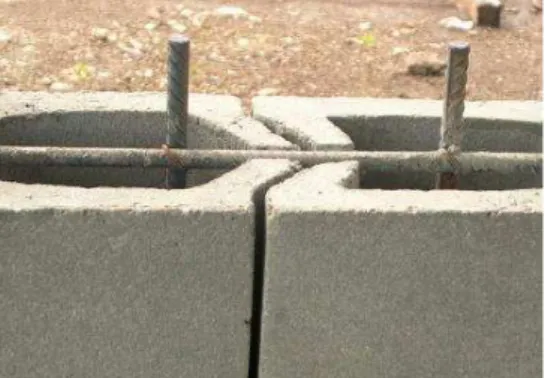
mm (6”x8”x16”). Figure 3 shows two adjacent interlocking blocks with vertical and horizontal rebar in
position.
Figure 3. Interlocking blocks with vertical and horizontal rebar
The blocks in consecutive layers were staggered. The base of the walls rested freely on a smooth
American Journal of Engineering Research (AJER)
2016
w w w . a j e r . o r g
Page 90
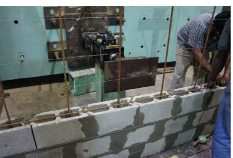
Figure 4. Wall section under construction with vertical and horizontal rebar
III.
TEST PROCEDURE
Comparative retaining force tests were conducted on the six cured retaining wall sections. The apparatus used to apply the horizontal force was the 793 Series MTS Actuator. This linear actuator measured simultaneously the horizontal force (N) (± 0.1N) and the respective wall deflection (mm) (±0.01 mm). Figure 5 shows a picture of the linear actuator. Once the test started the apparatus was automatically controlled by a computer that recorded the force and corresponding wall deflection data at one second intervals. Each test proceeded until the wall failed.
Figure 5. The 793 Series MTS Actuator
American Journal of Engineering Research (AJER)
2016
w w w . a j e r . o r g
Page 91
Figure 6. Schematic of wall section test set-up.
IV.
TEST RESULTS
Each cured specimen of the free standing retaining wall sections, simply-supported vertically at both ends, was tested to determine the horizontal retaining force. The specimens were subjected to a centrally located horizontal force using the 793 Series MTS Actuator apparatus and the variation of horizontal force with horizontal wall displacement was recorded automatically by the computer at one second intervals until the wall section was broken. The test results for the three wall sections constructed with the interlocking concrete blocks and 13 mm vertical rebar in the concrete filled core are shown below in Figures 7 to 9. The maximum retaining force and corresponding displacement for each test were noted.
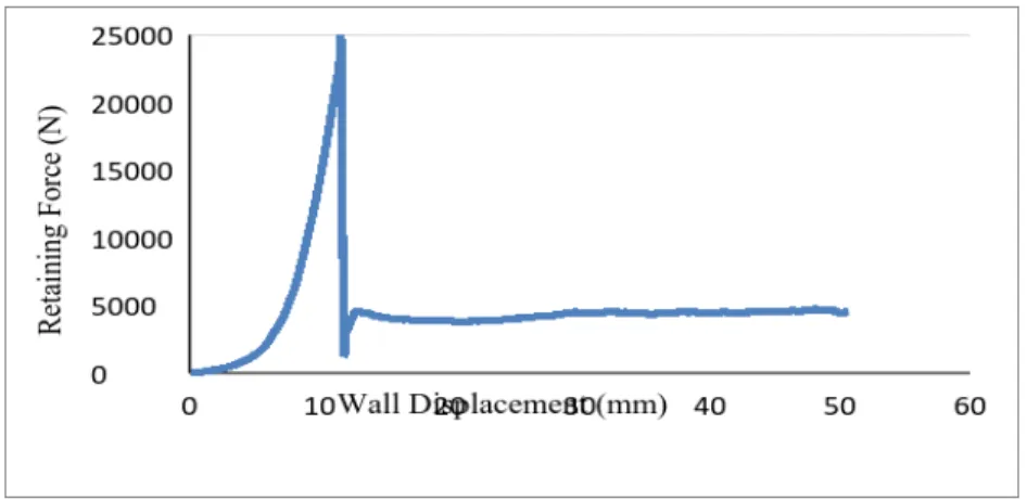
Figure 7. Force displacement variation for specimen 1 - interlocking concrete blocks with 13 mm vertical rebar
The test results shown on figure 7 indicated a maximum retaining force of 23637.81 N at a wall deflection of 11.6664 mm. The sudden drop in retaining force indicated that structural failure occurred beyond this point.
American Journal of Engineering Research (AJER)
2016
w w w . a j e r . o r g
Page 92
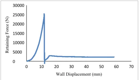
The test results shown on figure 8 indicated a maximum retaining force of 25942.31 N at a wall deflection of 16.5014 mm. The sudden drop in retaining force indicated that structural failure occurred beyond this point.
Figure 9. Force displacement variation for specimen 3 - interlocking concrete blocks with 13 mm vertical rebar
The test results shown on figure 9 indicated a maximum retaining force of 24059.28 N at a wall deflection of 11.8328 mm. The sudden drop in retaining force indicated that structural failure occurred beyond this point.
The average retaining wall strength from the three test for the interlocking concrete block retaining wall with 13 mm vertical steel rebar and concrete filled cores was 24546 N at an average wall deflection of 13.3 mm.
The test results for the three wall sections constructed with the interlocking concrete blocks and 13 mm vertical rebar and 13 mm horizontal rebar and concrete filled cores are shown below in Figures 10 to 12. The maximum retaining force and corresponding displacement for each test were noted.
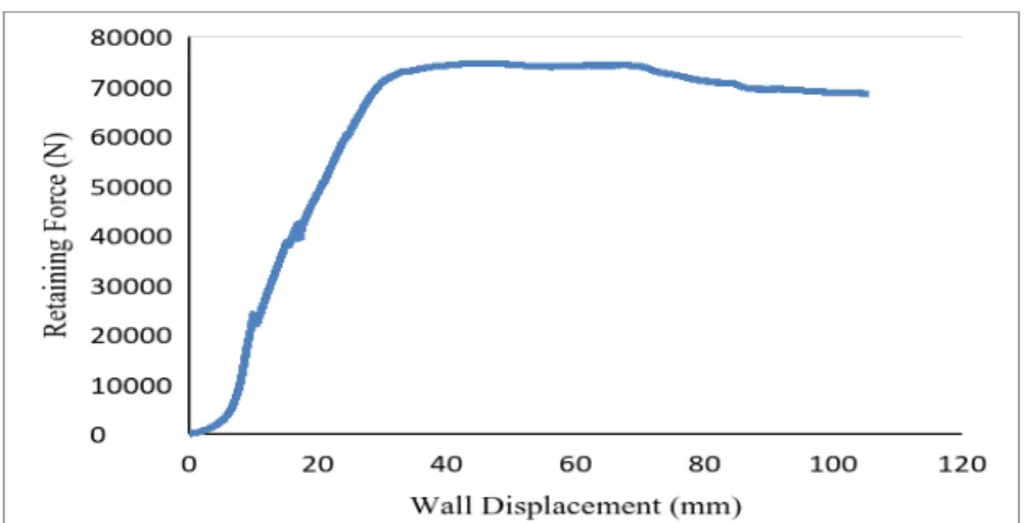
Figure 10. Force displacement variation for specimen 4 - interlocking concrete blocks with 13 mm vertical and
horizontal rebar
American Journal of Engineering Research (AJER)
2016
w w w . a j e r . o r g
Page 93
Figure 11. Force displacement variation for specimen 5 - interlocking concrete blocks with 13 mm vertical and
horizontal rebar
The test results shown on figure 11 indicated a maximum retaining force of 91621.3 N at a wall deflection of 47.0002 mm.
Figure 12. Force displacement variation for specimen 6 - interlocking concrete blocks with 13 mm vertical and
horizontal rebar
The test results shown on figure 12 indicated a maximum retaining force of 74587.08 N at a wall deflection of 43.1668 mm.
The average retaining wall strength from the three test for the interlocking concrete block retaining wall with 13 mm vertical and horizontal steel rebar and concrete filled cores was 80776 N at an average wall deflection of 48.2 mm.
V.
DISCUSSION
Staggered layer concrete block retaining walls with vertical rebar and concrete filled cores are convenient, attractive looking and commonly used for small to medium scale landscaping projects. The use of horizontal rebar are not common as the majority of commercially available concrete block designs do not accommodate for the installation. The horizontal retaining force experiments were designed to simulate a horizontal force loading on a free standing retaining wall section as shown in Figure 6.
American Journal of Engineering Research (AJER)
2016
w w w . a j e r . o r g
Page 94
Experimental results on the three wall specimens for the interlocking blocks with vertical rebar, horizontal rebar and concrete filled cores showed an average horizontal retaining force of 80776 N at an average wall deflection of 48.2 mm. The maximum retaining force was 91621.3 N at a wall deflection of 47 mm and the minimum retaining force was 74587.08 N at a wall deflection of 43.2 mm. This showed that the calculated average retaining force was 80776 N ± 13.4% of the experimental results.
All three interlocking retaining wall section with horizontal and vertical rebar showed a higher retaining force than the three retaining wall sections with only vertical rebar. The calculated average retaining force for the wall section with both horizontal and vertical rebar was 3.29 times higher or 229% greater than the average retaining force for the wall section with only vertical rebar.
From the plot of retaining force vs displacement for the wall section with only vertical rebar shown in Figures 7 to 9, there was a sudden drop to almost zero in the retaining force after the point of failure. From the plot of retaining force vs displacement for the wall section with vertical and horizontal rebar shown in Figures 10 to 12, there was a comparatively gradual drop in the retaining force after the point of failure. This indicated that the retaining wall with only vertical rebar will suddenly collapse on reaching the point of structural failure, however, the horizontal rebar prevented the sudden collapse of the wall.
VI.
CONCLUSION
Retaining wall test sections with horizontal and vertical rebar and concrete filled cores was more than three times stronger than retaining wall sections with only vertical rebar and concrete filled cores. Retaining wall sections with only vertical rebar and concrete filled cores collapsed suddenly on reaching the point of structural failure whereas retaining wall sections with both vertical and horizontal rebar and concrete filled cores showed a gradual reduction in retaining force after the point of structural failure.
REFERENCES
[1]. J. Ambrose, Simplified Design of Masonry Structures, 70-75, (New York: John Wiley and Sons, Inc., 1991).
[2]. The Family Handyman, How to Build a Concrete Block Retaining Wall. Accessed 26 August, 2016.
Available:http://www.familyhandyman.com/landscaping/retaining-wall/how-to-build-a-concrete-block-retaining-wall/view-all
[3]. B. Zaretsky, Segmental block retaining walls, The Journal of Light Construction. Accessed 26 August, 2016.
Available:http://www.jlconline.com/how-to/framing/segmental-block-retaining-walls_o
[4]. F. Javidan, M. Safarnejad and S. Shahbeyk, Shape optimization of hollow concrete blocks using the lattice discrete particle model,
Iranica Journal of Energy & Environment - Geo-hazards and Civil Engineering, 4(3), 2013, 243-250
[5]. T. Huang, Mechanical behavior of interconnected concrete-block retaining wall, Journal of Geotechnical and Geo environmental
Engineering, 123(3), 1997, 197-203.
[6]. Elite precast concrete, Interlocking concrete blocks. Accessed 26 August, 2016.
Available:http://www.eliteprecast.co.uk/interlocking-precast-concrete-blocks/duo-interlocking-concrete-blocks/
[7]. R. E. Curtiss, To determine the lateral (horizontal) force exerted on a retaining wall by the backfill behind it, under specified