Analysis of Three Dimensional Horizontal Reinforced Concrete
Curved Beam Using Ansys
T. Subramani
1, M. Subramani
2, K. Prasath
31
Professor & Dean, Department of Civil Engineering, VMKV Engineering College, Vinayaka Missions University, Salem, India.
2
PG Student of Structural Engineering, Department of Civil Engineering, VMKV Engineering College, Vinayaka Missions University, Salem.
3
PG Student of Irrigation Water resources and management Engineering, Department of Civil Engineering, VMKV Engineering College, Vinayaka Missions University, Salem.
ABSTRACT
Reinforced concrete horizontally curved beams are extensively used in many fields, such as in the construction
of modern highway intersections, elevated freeways, the rounded corners of buildings, circular balconies,….etc.
In some of these cases, large depths are needed for curved beams in order to resist high loads or to fulfill some aesthetic purposes. The analytical analysis of such members is very complex due to the fact that those members are subjected to combined action of bending, shear and torsion. Furthermore, non homogeneous nature of the materials involved contributes to the complexity of the problem. Therefore, it becomes necessary to employ numerical analysis procedures, such as the finite element method, to satisfy the safety and the economy requirements.A horizontally curved beam, loaded transversely to its plane, is subjected to torsion in addition to bending and shear. Furthermore, in deep beam the plane section does not remain plane after bending because of high stresses and warping occurs. Therefore, special features of analysis and design for horizontally curved deep beams is necessary to include the effect of above mentioned factors. Several methods of collapse analysis (Khalifa 1972, Jordaan et al. 1974, Badawy et al. 1977, Hsu et al. 1978, and Abul Mansur and Rangan 1981. ) were proposed for analysis of specific cases of reinforced concrete curved beams. However, till yet studies concerning reinforced concrete horizontally curved deep beams are rare. At present, with the application of digital computers beside the development of numerical methods, the mathematical difficulties associated with curved deep beam have been largely overcome. One of the most effective numerical methods utilized for analyzing reinforced concrete members is the finite element method. Using this method, many aspects of the phenomenological behaviour of reinforced concrete structures can be modelled rationally. These aspects include the tension-stiffening, non-linear multiaxial material properties, modelling of cracking and crushing, and many other properties related to the behaviour of reinforced concrete members under stresses. An important utilization of the finite element method is the modelling of the degradation of concrete compressive strength in the presence of transverse tensile straining as happens in members subjected dominantly to torsion or shear stresses. Therefore, the present study adopted a three dimensional non-linear finite element model to investigate the behaviour and the load carrying capacity of reinforced concrete horizontally curved deep beams.
KEYWORDS
: Analysis , Three Dimensional, Horizontal Reinforced Concrete, Curved Beam, AnsysI.
INTRODUCTION
In this study, a nonlinear three dimensional finite element analysis has been used to conduct an analytical investigation on the behaviour of curved in plan composite concrete-concrete beam using the analysis system computer program (ANSYS v.9.0 2004). Various types of beams, with available experimental results are chosen to check the validity and the accuracy of the adopted models. In general good agreement is obtained. The maximum percentage difference in ultimate load carrying capacity is 12%. Parametric studies are carried out to study the influence of the curvature (L/R ratio of 0, 0.1, 0.15 and 0.2) on the behaviour of the curved in plan composite concrete beams. Also, some important
material and solution parameters that affect the structure behaviour are studied. These include the slab thickness, support condition, compressive strength of concrete and the percentage of steel across the interface between the stem and the slab of the composite beam. This article contains the results of a study aimed at examining the stress analysis of a curved beam with a rectangular cross section with a neutral-line which is contained in a plane π. The forces that load the beam are located in the plane π. Bending moments have pseudo-vectors perpendicular to the same plane. These kinds of loads do not stress the beam with any torsion effect. Bending moment M, shear force T and axial force N are available at each point P of the beam. Stresses and are obtained without calculating the deformed line (today,
however, the Finite Element Method demands this kind of calculation). In fact, non standard stress analysis allows to calculate all the strains and stresses whilst only knowing the values of M, N, T and of the bending-radius ρn of the neutral-line at a given point in the neutral-line.
II.
CURVED BEAMS
One of the assumptions of the development of the beam bending relations is that all longitudinal elements of the bean have the same length, thus restricting the theory to initially straight beams of constant cross section. Although considerable deviations from this restriction can be tolerated in real problems, when the initial curvature of the beams becomes significant, the linear variations of strain over the cross section is no longer valid, even though the assumption of plane cross sections remaining plane is valid.
A theory for a beam subjected to pure bending having a constant cross section and a constant or slowly varying initial radius of curvature in the plane of bending is developed as follows. Typical examples of curved beams include hooks and chain links. In these cases the members are not slender but rather have a sharp curve and their cross sectional dimensions are large compared with their radius of curvature.
Fig 2.1 Curved beam element with applied moment, M
Fig is the cross section of part of an initially curved beam. The x-y plane is the plane of bending and a plane of symmetry. Assumptions for the analysis are: cross sectional area is constant; an axis of symmetry is perpendicular to the applied moment; M, the material is homogeneous, isotropic and linear elastic; plane sections remain plane, and any distortions of the cross section within its own plane are neglected. Since a plane section before bending remains a plane after bending, the longitudinal deformation of any element will be proportional to the distance of the element from the neutral surface. In developing the analysis, three radii, extending
from the center of curvature, O’, of the member are
shown in Fig 4.1. The radii are: r that references the location of the centroid of the cross sectional area; R that references the location of the neutral axis; and r
references some arbitrary point of area element dA on the cross section.
III.
CURVED BEAM AND FRAME
ANALYSYS
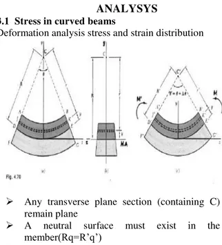
3.1 Stress in curved beams
Deformation analysis stress and strain distribution
Any transverse plane section (containing C) remain plane
A neutral surface must exist in the
member(Rq=R’q’)
Elongation of the arc JKàJ’K’, d=r’q’-rq
3.2 Curved Beam Stress Analysis 1) Draw a very good picture.
Show ri, ro, Area
Show the applied Force, F
2) Calculate the centroidal radius, R, based on the section type. (Hamrock § 4.5.3)
3) Compute the neutral radius, rn, based on the section type.
4) Compute the eccentricity, e = R - rn
5) Compute the moment about the centroidal radius, R. Here M = F x L, not F x R,
because the force is not through the center of curvature.
6) Calculate the distances from the neutral axis to the inner and outer surfaces:
ci = rn – ri and co = ro – rn.
8) Add or subtract any P/A stresses (using superposition).
9) As a check, compare the answer to MC / I for a straight beam with neutral axis on the centroid and see if it makes sense.
IV.
FINITE ELEMENT MODEL
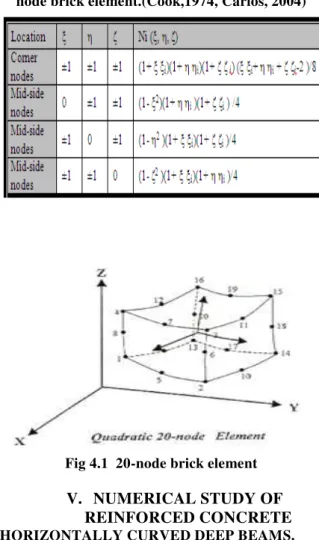
The 20-node isoparametric brick element shown in Fig.1 is used in the current study to model the concrete. Each node of this element has three degrees of freedom (u, v, and w) in the (x, y, and z) directions, respectively. The isoparametric definition of the brick element is(Al- Shaarbaf, 1990):
20 1
, , ,
,
i
i
i u
N
u ,
201
,
,
,
,
i
i
i
v
N
v
,
201
,
,
,
,
i
i
i
w
N
w
(1)where Ni (ξ, , ) is the shape function at the i-th node and ui, vi, wi are the corresponding nodal displacements. The shape functions for the 20 node brick element which are adopted to map the element are given in Table.
The Gauss-Legender quadrature numerical integration scheme has been found to be accurate and a convenient technique to carry out the finite element analysis. The integration rule, which has been used in this study , is the 15-point rule. The weights and abscissa of the sampling points are listed in Table.4.1 .The relative distribution of the Gaussion points over the element is given fig 4.1
Table 4.1 Shape functions of the quadratic 20-node brick element.(Cook,1974, Carlos, 2004)
Fig 4.1 20-node brick element
V.
NUMERICAL STUDY OF
REINFORCED CONCRETE
HORIZONTALLY CURVED DEEP BEAMS.
This section illustrates a numerical study that was carried out on reinforced concrete horizontally curved beams with different depths to investigate the effect of some important parameters on the load-deflection response of curved beams and the ultimate load resisted by those beams. The parameters included in this study were the total depth of the beam, subtended angle, boundary conditions, amount of transverse steel reinforcement ,use additional longitudinal bars, besides change the location of load. The reinforced concrete horizontally curved beam tested by (Jordaan et al., 1974), subjected to single point load was adopted in this numerical study.
5.1 The Influence of the Depth of the Beam
Table shows the results of the ultimate load for different total depths with their ratios of the shear length (length of curved segment of beam)to the effective depth (a/d). Calculation of shear length for curved beams is shown in Fig.
Table 5.1 Effect of increasing depth (h) on the ultimate load
Fig 5.1 Shows the calculation of shear length (a)
Fig. 5.1 shows the influence of total length (h) increasing on the load-deflection response for the curved beams. This figure reveals that both initial and post cracking stiffness and the ultimate load are significantly increased as the total depth increased. This can be attributed to the fact that when the total depth is increased, the internal lever arm between the compression force in the concrete and the tensile force in tension reinforcement is significantly increased. Also , the capacity of the curved beam cross section in shear and torsion is increased as the area enclosed by the centerline of stirrups legs increases.
Fig. 5.2 shows the influence of the ratio of (a/d) on the ultimate load of curved beam. It can be concluded according to this figure that the ultimate load resisted by curved beams increases with decreases (a/d). For values of (a/d) lower than two (h >600 mm), the ultimate load increasing at a sharp slope with decreasing (a/d). This can be attributed to the effect of arch action on the behavior of the reinforced concrete curved beams.
Fig 5.2 Effect of depth (h) on load deflection behaviour
VI.
ANALYSIS RESULTS
Analysis results shown in Fig.6.1, Fig.6.2, Fig.6.3, Fig.6.4 & Fig.6.5
Fig 6.1 MESHING ELEMENT
Fig 6.2 NODAL SOLUTION
Fig 6.4 Y- COMPRESSIVE STRESS
Fig 6.5 CURVED BEAM
VII.
DESIGN RECOMMENDATIONS
1 From the foregoing discussion certain design recommendations, with respect to the shear strength of shear walls, suggest themselves 2 The careful consideration of shear strength
should not distract from the attention to be paid to flexure. The strength and the postelastic performance of shear wall must be governed by flexure. In this respect walls with H/D larger than 2 are likely to behave as large doubly reinforced concrete beams with ample ductility.
3 The benefit that may be derived in deep beams from arch action, as a major shear resistant mechanism after cracking, should be disregarded. The shear resistance of various mechanisms , other than the web reinforcement, should be assessed as in an ordinary beam, i.e. V c = 2bd>/f^. Web (horizontal) reinforcement should be provided for the remainder of the seismic shear.
4 The combined shear resistance, i.e. V u = V c + Vs , should be larger than the shear generated at the attainment of the maximum moment. Yielding of the web reinforcement should not occur.
5 Where diagonal cracks could open, as a consequence of yielding in the flexural reinforcement, the whole of the seismic shear should be resisted by suitable shear reinforcement. The height of the shear wall
affected by this requirement could be equal to its depth.
6 Vertical reinforcement placed in the core of shear walls, irrespective of this being nominal or not, must be included in the assessment of the ultimate flexural strength, at its true yield strength, to ensure that the shear strength provided is not exceeded. Apart from improving crack control and providing dowel resistance, vertical web reinforcement in shear walls is not likely to contribute towards shear strength.
VIII.
CONCLUSION
Based on the finite element analysis carried out in the present research on the behaviour of reinforced concrete horizontally curved deep beams, the following conclusions can be drawn:
1. The three-dimensional nonlinear finite element model, adopted in the present work, is suitable to predict the behaviour of the reinforced concrete curved deep beams. Application of this model is beneficial in spite of the difficulties arising due to the difference in representation of data between the polar coordinate system and Cartesian coordinate system. The numerical results are in good agreement with available experimental load-deflection results throughout the entire range of behaviour.
2. The ultimate load resisted by curved beams increased as the shear length to effective depth ratio (a/d) decreased. This increase of ultimate load becomes more effective when the shear length to effective depth ratio (a/d) was lower than two.
4. The effect of internal torsion, acting in the cross section of curved beams, on the ultimate load decreased as the (a/d) ratio decreased. The ultimate load resisted by curved beams decreases due to releasing the torsional restraint at one curved beam ends by 22% for (a/d= 4.36 ), while the decrease is 12% for (a/d= 1.75 ).
5. The increase in the amount of transverse reinforcement causes a corresponding increase in the ultimate load resisted by curved beams. The effect of the amount of transverse reinforcement on the ultimate load have been reduced when the (a/d) ratio is less than two. The increase in the ultimate load resisted by curved beams, due to varying the stirrup's diameter from 6.35 mm to 12 mm, decreases from 9.1% for (a/d= 2.51 ) to 5.2% for (a/d= 1.75 ).
6. Using additional longitudinal bars as a horizontal shear reinforcement leads to increase in the ultimate load of curved beams. This effect of using additional longitudinal bars is increase with decreasing of (a/d) ratio. The increase in the ultimate load resisted by curved beams, due to using four additional longitudinal bars(diameter 12 mm), increases from 3.77% for (a/d= 4.36 ) to 10.5% for (a/d= 1.75 ).
REFERENCES
[1]. Al- Shaarbaf, I.A.S., 1990, "Three-Dimensional Non-Linear Finite Element Analysis of Reinforced Concrete Beams in Torsion", PH. D. Thesis. University of Bradford, U.K.
[2]. Al- Tameemi, H.A.A., 2005, "Three-Dimensional Non-Linear Finite Element Analysis of Reinforced Concrete Horizotally Curved Deep Beams", M.Sc. Thesis. University of Kufa.
[3]. Al-Mahiadi. R.S.H., 1979, "Non-linear Finite Element Analysis of Reinforced Concrete Deep Beams", Report No. 79, Dept. of Structure Engineering, Cornell University.
[4]. Badawy, H.E.I, Jordaan, I.J., and McMullen, A.E., 1977 "Effect of Shear on Collapse of Curved Beams", Journal of the Structural Division, ASCE, Vol. 103, No. ST9, Proc. Paper 13185, September, pp. 1849-1866. [5]. Carlos A.F., 2004, "Introduction To Finite
Element Methods", Department of
Aerospace Engineering Sciencesand Center for Aerospace StructuresUniversity of Colorado, U.S.A.
[6]. Cervenka, V., 1985, "Constitutive Model for Cracked Reinforced Concrete", ACI Journal, Vol. 82, No. 6, November-December, pp. 877-882.
[7]. Chen, 1982, W.F., and Saleeb, A.F., "Constitutive Equations for Engineering Materials: Elasticity and Modeling", Vol.1, John Wiley and Sons, New York, U.S.A. [8]. Cook, R.D.,1974, "Concept and Application
of Finite Element Analysis", John Wiley and Sons, Inc., New York, U.S.A.
[9]. Hsu, T.T.C., Inan, M., and Fonticiella, L., 1978, "Behavior of Reinforced Concrete Horizontally Curved Beams", ACI Journal, Vol. 75, No. 4, April, pp. 112-123.
[10]. Jordaan, I.J., Khalifa, M.M.A., 1974, and McMullen, A. E., "Collapse of Curved Reinforced Concrete Beams", Proceedings, ASCE, Vol. 100, ST11, November, pp. 2255-2269.