*e-mail: [email protected]
Trabalho apresentado no XV CBECIMAT, Natal - RN, Novembro de 2002.
Manufacturing of Metallic Porous Structures
to be Used in Capillary Pumping Systems
Eduardo Gonçalves Reimbrecht*, Edson Bazzo, Luis Henrique Seabra Almeida,
Henrique Cislagui Silva, Cristiano Binder, Joel Louis Rene Muzart
Departamento de Engenharia Mecânica,
Laboratório de Combustão, Engenharia de Sistemas Térmicos, Campus Universitário, Bairro Trindade, 88040-900 Florianópolis - SC, Brazil
Received: January 1, 2003; Revised: July 1, 2003
Sintered metallic porous structures have an application as capillary structures in two-phase heat transfer loops. In this work the manufacturing procedure of tubular porous structures for capillary pump application is discussed. The application of porous structures on capillary pumping systems requires porosity higher than 40% and pore size diameter lower than 20 µm. Carbonyl nickel powder with particle diameter between 3 and 7 µm and stainless steel AISI316L powder with particle diam-eter between 1 and 22 µm were used as raw material. Sintering under hydrogen atmosphere was performed both in a resistive furnace and in a plasma reactor. Temperature and time were the modi-fied parameters to obtain suitable porosity and roundness on the samples. The porosity was meas-ured using the Arquimedes Principle (MPIF-42), the roundness was evaluated using a simplified measurement technique of the sample diameter and the pore size distribution was determined by image analysis techniques. Images obtained by Scanning Electronic Microscopy were employed on the image analysis. The sintering parameters selected to manufacture nickel samples were 700 °C and 30 min resulting in a porosity of about 44%. The sintering parameters selected to manufacture stainless steel samples were 1000 °C and 30 min resulting in a porosity of about 40%.
Keywords:Nickel porous structures, stainless steel porous structures, sintering, capillary pumping
1. Introduction
Porous structures are currently used in heat pipes, loop heat pipes (LHP´s) and capillary pumping loops (CPL´s). The porous structure is employed to generate the capillary pumping pressure required to transport a working fluid along two-phase heat transfer loops. Typical porous structures consist of grooved surfaces, wire meshes, screens or sintered metal powders1,2. Sintered porous samples have been con-sidered for capillary pump applications, using ammonia, acetone or propylene as working fluids3,4. Porous structure manufacturing by sintering was suggested due to the capac-ity of control the sample poroscapac-ity5-7. Sintering of steels is conventionally carried out in a furnace in a controlled at-mosphere. Recently, an alternative technique has been de-veloped using an abnormal glow discharge of argon and hydrogen gas mixture8-11, which is characterized by the full
covering of the cathode by the glow region12, supplying a uniform treatment. The principle of heating is based on the ion and fast neutrals bombardment of the sample. A nega-tively biased voltage was applied to the sample, acting as the discharge cathode, which generates an electric field in the cathode sheath, where ions are strongly accelerated. Collisions between ions and argon atoms or hydrogen mol-ecules in the cathode sheath result in a flow of fast neutrals toward the cathode12. The bombardment of ions and fast neutrals heat the sample. As a consequence of the uniform treatment provided by the plasma technique, suitable tem-perature homogeneity was obtained13.
due to temperature homogeneity7,8. The material choice de-pends on the working fluid selected and the required capil-lary action to pump the fluid. In general, LHP´s and CPL´s are efficient two-phase heat transfer devices to transport thermal energy, even at a very small temperature difference, without any external power requirements to pump the work-ing fluid. Both, the LHP and the CPL use capillary forces to pump the working fluid from heat acquisition systems to heat rejecting devices. In heat pipes, the heat loads and the heat transfer distances are limited by reason of the large liquid flow resistance in the porous structure. The selection of a sample has to take into account the permeability and the effective capillary pumping pressure to displace the liq-uid from the condenser to the evaporator. The smaller the effective pores size the higher the capillary pumping pres-sure. On the other hand, the sample permeability decreases with decreasing pore size. So, an optimal pore size for the structure has to be determined.
Polyethylene, stainless steel, titanium and nickel are all compatible with the employed working fluids and can be used as pumping structure. Ceramic materials have been tested in these systems too. In general, metallic materials have higher wettability than polymeric materials and higher tenacity than ceramic materials, considering the usually employed working fluids, for example, ammonia, acetone and propylene. These characteristics do the metallic mate-rials satisfactory to be employed in two-phase transfer sys-tems. In this work the manufacturing procedure of tubular porous structures for capillary pump application is discussed. The procedures for the production by sintering and charac-terization of the porous structures are presented here. The porosity, pore size distribution and roundness of tubular sam-ples made of nickel and stainless steel powders were analyzed. Porous structures have been produced by sintering tapped powders in order that the required parameters for capillary structures, such as porosity higher than 40% and pore radius smaller than 10 µm9.
2. Materials and Methods
2.1. Manufacturing
A tap powder sintering technique was used to manufac-ture the tubular porous samples in a stainless steel die. The sintering process was conducted in a commercial hydrogen controlled-atmosphere using a resistive furnace JUNG model TU-3513. The resistive furnace has not space to use the die at vertical position. Another route was employed to manu-facture the samples in a plasma reactor with an atmosphere of 70% Ar - 30% H2. The used plasma reactor can be ob-served in the Fig. 1.
Carbonyl nickel powder (NP-123) and stainless steel AISI316L powder were used as raw materials. They are compatible with ammonia and others working fluids
typi-cally used in heat pipes, LHP’s and CPL’s. The nickel pow-der carbonyl 123 was provided by Inco Co. (USA) with a particle size in the range of 3 to 7 µm (specific surface area: 0.3 - 0.4 m2/g). The shape of the NP-123 is spherical and its surface has many spikes. The used stainless steel powder has a particle size in the range of 1 to 22 µm and a D90 of 20 µm. The stainless steel powder is spherical, uniform and smooth. Preliminary nickel samples manufacturing tests showed that the sintering time of 30 min is appropriate. A sintering schedule was fixed to manufacture the nickel sam-ples, with selected time of 30 min and temperatures in the range of 600 to 700 °C, varying at 50 °C intervals. Another sintering schedule was fixed to manufacture the stainless steel samples, with selected time of 30 min and tempera-tures in the range of 950 to 1000 °C, varying at 25 °C inter-vals. Each sintering temperature schedule was repeated six times to increase data reliability for porosity and roundness of the tubular samples.
2.2. Porosity
The total porosity of the samples was first determined by the Arquimedes method according to Eqs. 1 and 2, where, ε is the volumetric fraction of pores of the sample (%), ρ is the apparent specific mass (g/cm3), ρ
Ni is the specific mass of the nickel (ρNi = 8.9 g/cm3), E is the thrust of the material immerged in mercury (ρHg = 13.6 g/cm3), m is the mass (g) and g is the gravitational acceleration (m/s2). For the
urements, an electronic scale Mars model A1600 (resolu-tion: 0.01 g) was employed.
(1)
(2)
2.3. Roundness
The roundness is another important parameter to be con-sidered in the manufacturing process. The lower the diam-eter deviation (roundness) the lower the thermal resistances to the heat transfer. For capillary pump applications no gaps are desirable, since they increase the thermal resistance, re-ducing the heat transfer and the heat load capacity. In order to get an appropriate fitting inside the capillary pumping devices, the external diameter is the geometric parameter of the sample that must be strongly controlled. So the round-ness was measured for each group of 4 samples submitted to the same sintering conditions. A total of ten measure-ments (φj), along every sample, were made to obtain a mean value for the diameter (φm). The roundness (λ) was deter-mined by Eq. 3, where n is the total number of measure-ments and j = 1 to n.
(3)
2.4. Image analysis
The image analysis technique was used to determine the pore size distribution in two-dimensional (2D) binary images of the microstructure. The levels of porosity, as well as the pore size distribution, were measured on images acquired by SEM from a set of samples prepared in the laboratory. From the same samples, manufactured in plasma reactor, images were acquired by optical microscopy. The pore size distribution is obtained by successive aperture, a
morpho-logical operation, by balls of increasing radius10. Basically, the method consists in the comparison of the pores image with a pattern. The resulting image after the application of the aperture, with a given ball radius, can be seen as the union of balls completely enclosed in the porous phase. Thus, after the aperture, the image contains the pores with radius larger than the radius of the ball. A computer pro-gram named IMAGO was used, where aperture is performed with octagonal balls generated by a quasi-Euclidian metric, the d3-4 metric11. The cumulative porous distribution is given by Eq. 4, where e is the total porosity of the original image and ε(r) is the porosity of the image after the aperture by a ball with radius r12.
(4)
3. Results
3.1. Manufacturing
The first step to manufacture a porous sample was to identify the optimal sintering parameters with respect to time and temperature. Porosity, roundness and pore size distri-bution were analyzed to determine the most appropriate sintering temperature. Sintered nickel and stainless steel samples with length of 10 cm and diameter of 2 cm can be observed in Figs. 2a and 2b respectively. These samples were sintered in a resistive furnace.
3.2. Porosity
The porosity values for the tubular samples produced with nickel powder and stainless steel powder are plotted in Figs. 3a and 3b respectively. The porosity was not affected by fur-nace type because all samples were sintered inside the die. For nickel samples a porosity level in the range of 43.7 to 51.9 vol.% was found. Besides that, the porosity samples showed dependence on the sintering temperature. For stain-less steel a porosity level in the range of 35.4 to 40.7 vol.% was found. With this material, the porosity samples did not show dependence on the tested sintering temperature.
Although high porosity is advantageous for use in
cap-Figure 2. a) porous nickel sample sintered at 700 °C/30 min; b) porous stainless steel sample sintered at 1000 °C/30 min.
illary pumps, this implies in a lower mechanical resistance. In this work, the mechanical resistance was not measured directly. It was assumed that the sample has a satisfactory mechanical resistance since it can support the compressive efforts during the assembly of the heat transfer device.
3.3. Roundness
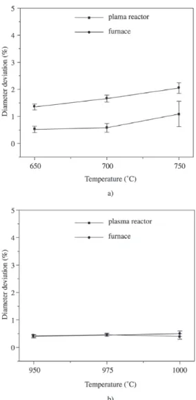
The diameter deviation values for the tubular samples produced with nickel powder and stainless steel powder are plotted in Fig. 4a and 4b respectively.
The diameter deviation of the porous structures produced from the NP-123 (approximately 1%) makes it difficult to fit them inside the heat transfer devices. In order to assemble the heat transfer devices with NP-123 samples, it was
neces-Figure 4. Diameter deviation: a) nickel samples; b) stainless steel samples.
sary to machine them. Probably, the diameter deviation dif-ference showed in Fig. 4a is due to the die position during the sintering - vertical in the plasma reactor and horizontal in the furnace. The diameter deviation of the porous structures produced from the stainless steel powder (approximately 0.5%) makes it possible to fit them inside the heat transfer devices. The die position and furnace type did not change the diameter deviation of stainless steel samples as showed in Fig. 4b. The stainless steel samples present higher diameter deviation than nickel samples due to the stainless steel sam-ples present lower shrinkage than nickel samsam-ples.
3.4. Image analysis
The microphotographs of a nickel sample obtained by
Figure 5. a) Image of a nickel sample sintered at 700 °C/30 min obtained by SEM; b) image of a stainless steel sintered at 1000 °C/30 min obtained by optical microscopy.
a) b)
Scanning Electronic Microscopy (SEM) and a stainless steel sample obtained by optical microscopy are shown in Fig. 5. Two methods of image acquisition were employed, and the results obtained by image analysis were the same for both. The porosity obtained by image analysis is showed in the Table 1, where is shown the comparison with the ex-perimental porosity. An acceptable agreement can be ob-served on the porosity results.
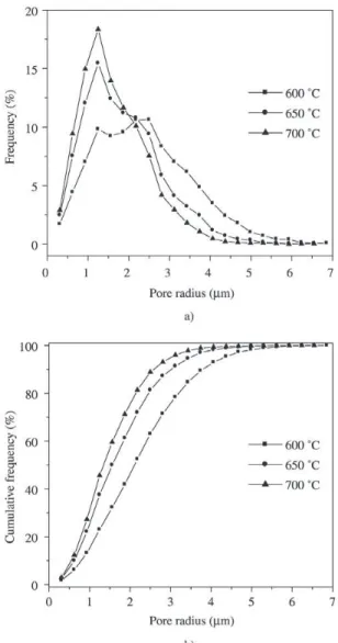
In Fig. 6 the pore size distribution curves for the sintered nickel samples are shown. The pore radius varies from 0.5 to 7 µm and the medium pore radius decreases with the increase of the temperature. The average pore radius is about 1.5 µm and D50 is about 1.3 µm to samples sintered at 700 °C.
In Fig. 7 the pore size distribution curves for the stain-less steel samples are shown. There is only a curve to sam-ples sintered at 1000 °C for 30 min because the tested sintering parameters did not influence the pore size distri-bution. The pore radius varies from 0.5 to 8 µm, the average pore radius is about 2 µm and D50 is about 1.6 µm.
It is important to control the pore size for the capillary pumping structures. The smaller the pores size, the higher
Figure 6. Pore size distribution of sintered nickel samples.
Table 1. Porosity.
Experimental Image analysis (Arquimedes) (%) (%) Nickel 600 °C/30 min 50.7 ± 1.8 54.7 ± 0.5 Nickel 650 °C/30 min 46.2 ± 1.1 47.7 ± 0.9 Nickel 700 °C/30 min 43.7 ± 2.3 42.4 ± 1.1
Stainless steel
the capillary pumping pressure. In addition, it is important to observe that the largest interconnected pores will deter-mine the effective capillary pressure.
4. Conclusions
Nickel powder and stainless steel powder were consid-ered satisfactory as raw materials for the production of cap-illary structures to be used in capcap-illary pumping systems.
Presented results considered, the best nickel samples were manufactured at 700 °C/30 min.The nickel samples presented the required porosity level (≅ 40%), diameter de-viation (≅ 1%), and acceptable mechanical resistance. Im-age analyzes was employed to determine the porous size distribution showing that the pore radius varies from 0.5 to 7 µm, the average pore radius is about 1.5 µm and the D50 is about 1.3 µm.
Presented results considered, the best stainless steel sam-ples were manufactured at 1000 °C/30 min.The stainless steel samples also presented satisfactory porosity level (≅ 40%), diameter deviation (≅ 0.5%), and acceptable me-chanical resistance. Image analysis was employed to deter-mine the porous size distribution showing that the pore ra-dius varies from 0.5 to 8 µm, the average pore radius is about 2 µm and the D50 is about 1.6 µm.
References
1. Peterson, G.P. An Introduction to Heat Pipes, Modeling, Testing and Applications, John Wiley & Sons, Inc., New York, 1994. 2. Dunn, P.D.; Reay, D.A. Heat Pipes, Pergamon Elsevier Sciense
Ltd., 4th Edition, London, 1994.
3. Maidanik, Y.U.F.; Fershtater, Y.U.G.; Goncharov, K.A. Capillary-pump Loop for Systems of Thermal Regulation of Spacecraft, 4th
European Symposium on Space Environmental an Control Sys-tems, San Diego, July 1991.
4. Ku, J.; Ottenstein, L.; Rogers, P.; Cheung, K. Investigation of Low Powder Operation in a Loop Heat Pipe, 30th International
Confer-ence on Environmental Systems, Orlando, July 2001.
5. Maidanik, Y.U.F. State-of-the-art of CPL and LHP Technology, 11th
International Heat Pipe Conference, Tokyo, September 1999. 6. Reimbrecht, E.G.; Fredel, M.C.; Bazzo, E.; Pereira, F.M.
Manufac-turing and Microstructural Characterization of Sintered Nickel Wicks for Capillary Pumps, Materials Research, v. 2, n. 3, p. 225-229, 1999.
7. Tracey, V.A. Usage, Manufacture and Properties of Porous Sintered Nickel, Powder Metallurgy International, v. 16, n. 4, p. 167-170, 1984.
8. Batista, V.J.; Binder, R.; Klein, A.N.; Muzart, J.L.R. Sintering Iron Using an Abnormal Glow Discharge, Inter. J. of Powder Metal, v. 34, n. 8, p. 55-62, 1998.
9. Brunatto, S.F.; Kühn, I.; Muzart, J.L.R. Influence of the Radial Spac-ing Between Cathodes on the Surface Composition of Iron Sam-ples Sintered by Hollow Cathode Electric Discharge, Materials Research, v. 4, n. 4, p. 245-250, 2001.
10. Brunatto, S.F.; Kühn, I.; Klein, A.N.; Muzart, J.L.R. Sintering Iron using a Hollow Cathode Discharge, Material Science and Engineer-ing A, v. 343, p. 163-169, 2003.
11. Maliska, A.M.; Pavanati, H.C.; Klein, A.N.; Muzart, J.L.R. The Influence of Ion Energy Bombardment on the Surface Porosity of Plasma Sintered Iron, Material Science and Engineering A, v. 352, p. 273-278, 2003.
12. Chapman, B. Glow Discharge Processes: Sputtering and Plasma Etch-ing, John Wiley & Sons, Inc., New York, 1980.
13. Reimbrecht, E.G.; Binder, C.; Almeida, L.H.S.; Philippi, P.C.; Muzart, J.L.R. Sinterização via Plasma de Elementos Porosos de Aço Inoxidável AISI316L para uso em Bombas Capilares, 57° Congresso Anual da ABM, São Paulo, Julho 2002.
14. Coster, M.; Chermant, J.L. Precis d’Anayse d’Images, Presses du CNRS, Paris, 1984.
15. Laurent, J.P.; Moschetto, C. Une Méthode Optimisée de Granulométrie par Analyse d’Images. Collque “Contrôle Qualité par Vision Artificielle”, Le Creusot, 1993.
16. Fernandes, C.P. Caracterização Morfológica de Espaços Porosos: Reconstituição Multiescala e Simulação de Processos de Invasão de Fluidos Não-molhantes, Tese de Doutorado, Universidade Federal de Santa Catarina, Florianópolis, 1994.