Materials Research, Vol. 8, No. 2, 117-120, 2005 © 2005
*e-mail: [email protected]
Synthesis and Characterization of PtRu/C Catalysts Obtained by
Colloidal and Deposition Methods for Fuel Cell Applications
Egberto Gomes Francoa,c,d,e, Almir Oliveira-Netoa, Estevam Vitório Spinacéa, Marcelo Linardia*,
Nathalie Martzb, Marian Mazurekb, Hartmut Fuessb
aInstituto de Pesquisas Energéticas e Nucleares - IPEN/CNEN - SP, Brazil bTechnical University of Darmstadt, Germany
cUniversidade Bandeirante de São Paulo, Brazil dCentro de Ensino Superior de Barueri, Brazil
eFaculdades Ítalo-Brasileira, Brazil, Brazil
Received: November 23, 2003; Revised: February 1, 2005
The purpose of this investigation was to compare catalysts produced by the Bönnemann - colloidal method (PtRu (B1) and PtRu (B2)), and those produced by the spontaneous deposition method (PtRu (SD)). The catalysts produced by both methods had good electrochemical behavior for methanol oxidation for proton exchange membrane fuel cell applications. The structure of the catalyst was examined by transmission electron microscopy (TEM). Energy dispersive spectroscopic analysis (EDS) was used to determine the semi-quantitative composition of the catalysts, and the electrochemical behavior was determined by cyclic voltammetry (CV). The diffractograms of the binary catalysts revealed platinum and ruthenium as the only crystalline phases, as per ICDD data base. The PtRu (B1) catalyst, treated in a reducing atmosphere, has the same structure as PtRu (B2), treated in an oxidising/reducing atmosphere, except that the crystallite size was around 1.7 nm for PtRu (B1) instead of 9.9 nm for PtRu (B2). The catalysts PtRu (B2) and PtRu (SD) showed similar cyclic voltammetric behavior, which was better than that of PtRu (B1).
Both methods are suitable for the production of electrocatalysts for fuel cell applications. The colloidal method is more expensive than the deposition method, but the former permits the production of ternary and quaternary catalyst systems with enhanced CO tolerance.
Keywords:fuel cell, catalyst, methanol, electrocatalyst, nanocrystal
1. Introduction
Sustainable development is one of the main concerns of industry in this century. Nevertheless, fuel cell technology has a promising future in the field of electricity generation with less environmental impact1.
One of the most important areas in fuel cell research is the devel-opment of new catalysts to increase electroactivity related to H2/CO, methanol and ethanol oxidation. To minimize contamination caused by CO adsorption on Pt sites, different techniques for synthesizing catalysts have been reported in the literature2-4. In this investigation different catalysts have been synthesized by two different methods: the Bönneman5 method and spontaneous deposition6-8.
X-ray diffraction (XRD)analysis, transmission electron micros-copy (TEM), energy dispersive spectroscopic analysis (EDS) and cyclic voltammetry (CV) were used to characterize the structure and electrochemical activity of the catalysts.
The synthesis of catalysts has been investigated widely8 and it is well known that the different methods of synthesis lead to different behavior in the catalysts. In this context, a lot of work has been done to correlate the electrochemical behavior of the electrocatalyst and its structure.
Two different methods were selected to synthesize the electrocata-lysts. The Bönnemann´s method was selected for doping the carbon black (electrode material) with the electrocatalyst, in a modified manner9, which consisted of a colloidal system in a dry nitrogen atmosphere, and used anhydrous solvents and salts of the metals. The Bönnemann method gives a crystallite, with an average size between 1.5 to 3.0 nm, that is well dispersed in the carbon matrix10. The spon-taneous deposition method was the other method, and consisted in
the spontaneous deposition of a monolayer of platinum on the surface of the ruthenium support. This method was chosen because it gives a high electroactivity, per gram of platinum used. Catalysts obtained by both methods showed interesting electrochemical behavior.
2. Experimental
2.1. Bönnemann’s method
To obtain the nanocrystal, a stable colloid should be prepared in an inert and dry atmosphere. The proper amounts of chloride salts of the metals involved were dissolved in anhydrous tetrahydrofuran (THF) with a proper amount of tetraoctilamoniyoum bromide [N(oct)4Br], while the reducing agent was prepared by the dissolu-tion of tetraoctilamoniyoum bromide [N(oct)4Br] in THF, by adding potassium trietilhydroborate [KHBr(Et) 3]. After stirring, a strong reducing agent is formed (trietilhydroborate of tetraoctilamonyoum [N(oct)4HBr(Et) 3]) according to Equation 1:
N(oct)4Br + KHB(et)3m N(oct)4HB(et)3 + KBrn (1) THF
118 Franco et al. Materials Research
MeXn + N(oct)4HB(et)3mMe*;N(oct)4=++ nB(et) nB(et)
3 + (2)
n/2 H2l + nX- THF colloid
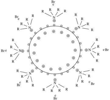
Adsorption of the [N(oct)dsorption of the [N(oct)4]+ ion on the metallic surface forms the stable colloid with an average size of 1.5 to 3.0 nm. Up to this point all the steps are performed in an inert and dry atmosphere. The stable colloid is shown schematically in Figure 1.
After synthesis of the stable colloid, a suspension of the Vulcan carbon black in THF was prepared and the colloid solution added drop wise. The final stages in the preparation of the electrocatalyst consisted of filtration followed by multiple rinsing in THF and ethanol.
2.2. Spontaneous deposition
This method was recently reported by Adzic et al.6-8 to help mini-mize the amount of platinum used to synthesize the PtRu catalyst. According to the authors, only a quarter of a monolayer of platinum on ruthenium nanocrystals results in an electrocatalyst with higher activity and tolerance to CO poisoning of the platinum sites by H2/CO oxidation, compared to commercial catalysts of PtRu alloys.
To obtain an electrocatalyst with 20 wt. (%) of ruthenium, car-bon support (Vulcan XC-72R) was impregnated with a solution of RuCl3.1.5H2O (Aldrich) in water: ethanol (1:1, v/v) and dried at 343 K for 4 hours. The solids obtained were heated from room temperature to 673 K at 1 K min-1 in a flowing argon atmosphere. Upon reaching the temperature, hydrogen gas was introduced and the sample was held at this temperature for 2 hours. The sample was then cooled to room temperature under flowing hydrogen and then immersed in an aque-ous solution of H2PtCl6 (0.01 mol L-1) held in an argon atmosphere. The mixture was stirred for 15 minutes, filtered, washed thoroughly with water and dried at 343K for 3 hours.
2.3. Structural characterization of the electrocatalyst powder by EDX, XRD and HRTEM.
A Philips XL 30 scanning electron microscope with EDX was used to examine the morphology of the powder and to determine the semi-quantitative composition of the catalyst powder.
X-ray powder diffraction analysis was carried out in a STOE STADI-P powder diffractometer, with germanium monochromatized CuKA
radia-tion and a posiradia-tion-sensitive detector with 40° aperture in the transmission mode, with 2Q scanned from 10 to 90° at a scan rate of 0.03° s-1.
A Philips CM 20 transmission electron microscope (TEM) with an acceleration voltage of 200 kV and a tungsten cathode was used to obtain high resolution images of the catalysts. The microscope was equipped with a nano-EDX device to determine the catalyst’s composition in nm-sized regions. The TEM samples were prepared by suspending the catalyst powder in methanol and depositing a drop of the suspension on a standard copper grid covered with carbon. These analyses, (XRD and HRTEM) were carried out at the Materials Sci-ence Institute of the Technical University of Darmstadt.
2.4. Electrochemical investigations
The electrochemical investigations consisted of cyclic voltam-metry (CV) with an EGG Princeton Applied Research Model 273 in a N2 saturated 0.5 mol L-1 H
2SO4. Methanol oxidation was evaluated with solutions containing three different concentrations of methanol, 0.1 mol L-1, 0.5 mol L-1, 1.0 mol L-1, at 25 °C. The working electrode consisted of a thin porous layer of the catalyst as dispersed nanoparti-cles in carbon black with a high surface area. The reference electrode was a RHE and the counter electrode was a platinized Pt plate. As reported earlier, the electrocatalyst produced by the Bönnemann`s method usually contains some adsorbed species from the protective shell formed around the colloid11. These species block the active platinum sites. Despite this, a heat treatment in a reducing atmosphere (H2) improves the electroactivity of the catalysts. Neto et al.12 reported that PtRuNi electrocatalysts prepared by the Bönnemann method and then heat treated showed higher electroactivity than the same catalysts without heat treatment. The cyclic voltammetric results revealed that the heat treated catalyst exhibited improved electroactivity. This heat treatment was carried out in a nitrogen/hydrogen atmosphere for 2 hours at 300 °C, followed by furnace cooling13. Another heat treat-ment was also carried out with the Bönnemam catalysts, which used oxidising and reducing atmospheres14,15 at 300 °C. The heat treatment was first carried out in an inert atmosphere until the catalysts reached 300 °C. Subsequently a small flow of oxygen was used for 20 minutes and this was followed by hydrogen for 2 hours.
3. Results
In order to simplify, the catalysts synthesized by the Bönneman´s method and heat treated in the reducing atmosphere is labeled as PtRu (B1), while the catalyst heat treated in the oxidizing/reducing atmosphere is labeled as PtRu (B2). The catalyst synthesized by spontaneous deposition is labeled as PtRu (SD).
3.1. Catalyst composition
The compositions of the catalysts were determined by EDX and the results are presented in Table 1.
The compositions of the catalysts synthesized by the Bönnemann method are in agreement with the experimental procedure. The composition of the catalyst obtained by the spontaneous deposition method reveals the presence of a small amount of platinum on the surface of the ruthenium supported-nanocrystals.
3.2. X-ray diffraction (XRD)
The diffractograms of the binary catalysts reveal platinum and
Table 1. Atomic ratios of Pt and Ru in the electrocatalysts.
Element PtRu (B1) PtRu (B2) PtRu (SD)
Platinum 59 59 10
Ruthenium 41 41 90
Vol. 8, No 2, 2005 Synthesis and Characterization of PtRu/C Catalysts Obtained by Colloidal and Deposition Methods for Fuel Cell Applications 119
ruthenium as the only crystalline phases, as per the ICDD data base. No evidence of other metallic phases or crystalline oxide species was found. Almost complete reduction of the educts was achieved, as no reflections of any metal chlorides appear in the patterns. The diffractograms can be seen in Figure 2.
A major difference can be observed between the results of the catalysts PtRu (B1) and PtRu (B2). As both the catalysts were pro-duced in the same batch, one can conclude that the only difference is the heat treatment procedure. The average crystallite size seems to increase in the following order: PtRu (B1) < PtRu (SD) < PtRu (B2). This result is in agreement with the high-resolution micrographs of the catalysts (Figures 3 and 4). The diffractogram of the support (Vulcan carbon black) indicates that the peaks with 2Q around 24.520, 43.4 and 79.780 are influenced by the carbon support. The diffractograms of the binary catalysts reveal platinum and ruthenium as the only crystalline phases as per the ICDD database. No evidence of other metallic phases or crystalline oxide species was found. Almost com-plete reduction of the educts was achieved, as no reflections of any metal chlorides appear in the patterns of the catalysts synthesized by the Bönnemann method. These results are in good agreement with data reported by Radmilovic et al.16and others17-19.
Despite the fact that a majority of the authors agree about the use of X-ray diffraction for analysis, Rolinson et al.20state that X-ray dif-ff
fraction is not a suitable method to characterize the phases in catalysts. Rolinson stressed that XRD measurements indicate the presence of Pt (FCC) phase only, but by using TGA/DTA and XPS measurements, the results indicate that the catalyst is composed of hydrated and unhydrated ruthenium oxides, that could be amorphous20.
3.3. High-resolution transmission electron microscopy (HRTEM)
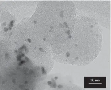
Nanocrystallites of catalysts PtRu (SD) and PtRu (B2) are shown in Figures 3 and 4. The catalytically active particles are well dispersed on the support grains in both samples. Compared to results published by Schmidt et al.14 for PtRu, bigger crystallites were observed in
catalysts synthesized by the Bönnemann method and heat treated with oxidising/reducing atmospheres. Similar growth in crystallite size was observed in the case of samples prepared by the spontaneous deposition method, but to a lesser extent. The HRTEM results are in good agreement with the shape of the diffractograms of the 3 samples. The first catalyst, PtRu (B1), has a small crystallite size that is difficult to resolve by XRD, the second catalyst with the largest crystallites, are in good agreement with the FWHM for this catalyst and the third catalyst had medium sized crystallites and some agglomerates. The catalyst PtRu (B1) has been described in the literature to have an average size of 1.7 nm21.
The PtRu (B1) catalyst has the same structure as that of PtRu (B2), except that the crystallite size is around 1.7 nm instead of 9.9 nm. The nanocrystals are well dispersed on the carbon support, similar to PtRu (B1).
3.4. Cyclic voltammetry (CV)
The three catalysts were tested by cyclic voltammetry to evaluate their electrochemical activity. Cyclic voltammetry was performed with sulfuric acid (H2SO4 0.5 mol L-1) as a support electrolyte and
to record the basic voltamogram of each catalyst. After this, other voltamograms were recorded as a function of methanol concentra-tions, 0.1 mol L-1, 0.5 mol L-1 e 1.0 mol L-1. To compare the results,
voltamograms corresponding to methanol concentration of 1.0 mol L-1
were chosen because this is the concentration often used in fuel cell operation. A scan rate of 10 mV s-1 was used in the experiments.
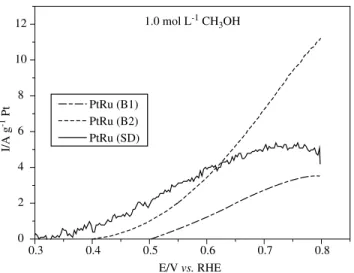
The results of electrooxidation of methanol with these catalysts are shown in Figure 5.
Figure 2. Diffractograms of the catalysts PtRu (B1), PtRu (B2) and PtRu (SD).
Figure 3. Nanocrystals of PtRu (SD) electrocatalyst dispersed in the carbon matrix. The crystallites have a bimodal distribution with an average size of 2.5 ± 0.4 nm and 5.2 ± 1.2 nm.
120 Franco et al. Materials Research
The catalyst produced by the spontaneous deposition method and the catalyst produced by the Bönnemann method and heat treated in oxygen present similar cyclic voltammetric behavior, especially in the range, 0.4 V to 0.7 V. This is of interest for direct methanol fuel cell applications. The catalyst synthesized by the Bönnemann method and heat treated only in hydrogen shows less electroactivity compared to the others.
4. Conclusions
The two methods are suitable for the production of electrocata-lysts for fuel cell applications.
The catalysts synthesized by the Bönnemann method present good electrochemical activity and a structure consisting of well-dispersed nanocrystals on the carbon support, leading to good electrochemical behavior for fuel cells applications.
The catalysts synthesized by the spontaneous deposition method also present good electrochemical activity, if the amount of platinum in the catalyst is normalised. The structure of the catalyst consists of platinum atoms on carbon-supported ruthenium nanocrystals.
The colloidal method (Bönnemann) should be performed in an inert atmosphere with non-hydrated chlorides of the metals involved becoming more expensive than the spontaneous deposition method. On the other hand, the colloidal method could produce ternary and quaternary systems of catalysts to improve their performance towards CO contamination.
Acknowledgments
The ‘Conselho Nacional de Desenvolvimento Científico e Tecnológico(CNPQ)’, ‘Fundação de Amparo a Pesquisa do Estado de São Paulo (FAPESP)’, and ‘Financiadora de Estudos e Projetos (FINEP – CTPETRO)’ are greatfully acknowledged for their finan-cial support, and the Technical University of Darmstadt for their laboratory support.
References
1. Linardi, M, Aricó, EM, Franco, EG, Célula de Energia. Revista de Química
Industrial. 2001; 717:7-13.
2. Shropshire, A. Catalysis of Electrochemical Oxidation of Formaldehyde
and Methanol by Molybdates. J. Electrochem. Soc. 1965; 112(5):465.
3. Gasteiger, HA, Markovic, N, Ross Jr, PN, Cairns, EJ. Carbon monoxide
electrooxidation on well-characterized platinum-ruthenium alloys. J.
Phys. Chem. 1994; 98:617-625.
4. Gasteiger, HA, Markovic, N, Ross Jr, PN. H2 and CO Electrooxidation on Well-Charactenzed Pt, Ru, and Pt-Ru. 1. Rotating Disk Electrode Studies
of the Puré Gases Including Temperature Effects. J. Phys. Chem. 1995;
99:8290-8301.
5. Bönnemann, HW Brijoux, R Brinkmann, E Dinjus, T Joussen. B Korall. Erzeugung von kolloiden Übergangsmetallen in organischer Phase und
ihre Anwendung in der Katalyse. Angew. Chem. 1991; 103:1344-1346.
6. Brankovic, SR, McBreen, J, Adzic, RR. Spontaneous deposition of Pt on
the Ru(0001) surface. J. Electroanal. Chem. 2001; 503:99-104.
7. Brankovic, SR, Wang, JX, Adzic, RR. Pt Submonolayers on Ru Nano-particles A Novel Low Pt Loading, High CO Tolerance Fuel Cell
Elec-trocatalyst.Electrochem. and Solid-State Lett. 2001; 4:A217–A220.
8. Brankovic, SR, Wang, JX, Adzic, RR. New methods of controlled mon-olayer-to-multilayer deposition of Pt for designing electrocatalysts at an
atomic level. J. Serb. Chem. Soc., 2001; 66(11–12):887–898.
9. Wendt, H, Götz, M, Linardi, M. Tecnologia de Células a Combustível.
Química Nova. 2000; 23-4:538–546.
10. Franco, EG, Aricó, E, Linardi, M, Roth, C, Martz, N, Fuess, H. Synthesis and characterization of eletrocatalyst powders for application in PEM fuel
cells; PTECH 2001, Third International Latin-American Conference on
Powder Technology, Florianópolis, Brasil, November 2001.
11. Oliveira Neto, A, Franco, EG, Aricó, E, Linardi, M, Gonzalez,ER. Electro-oxidation of methanol and ethanol on Pt-Ru/C and Pt-Ru-Mo/C
electrocatalysts prepared by Bonnemanns method. J. Europ. Ceramic
Soc. 2003; 23:2987-2992.
12. Oliveira Neto, A, Franco, EG, Aricó, E, Spinacé, EV, Linardi, M. Electro-Oxidation of Methanol and Ethanol on Pt-Ru/C and Pt-Ru-Ni/C based Electrocatalysts for PEM Fuel Cell Prepared by the Bönnemann´s Method.
Proccedings of Fuell Cells Science and Technology 2002 - Scientific Advances in Fuel Cells Systems, Amsterdam, Netherlands, 2002. 13. Franco, EG, Aricó, E, Linardi, M, Roth, C, Martz, N, Fuess, H. Synthesis
and Characterization of Electrocatalyst Powders for Applications in PEM fuel Cells. Mater. Sci. Forum. 2003; 416(4):4-10.
14. Schmidt, TJ, Gasteiger, HA, Behm, RJ. Methanol electrooxidation on a
colloidal PtRu-alloy fuel-cell catalyst.Electrochemistry Communications.
1999; 1(1):1-4.
15. Franco, EG, Oliveira Neto, A, Linardi, M, Aricó, E. Synthesis of Elec-trocatalysts by the Bönnemann Method for the Oxidation of Methanol
and the Mixture H2/CO in a Proton Exchange Membrane Fuel Cell. J.
Braz. Chem. Soc. 2002; 13:516-521.
16. Radmilovic, V, Gasteiger, HA, Ross Jr, P N. Structure and chemical com-position of a supported Pt–Ru electrocatalysis for methanol oxidation. J. Catal. 1995; 154:98-106.
17. Lasch, K; Jörissen, L; Garche, J. The effect of metal oxides as co-catalysts
for the electro-oxidation of methanol on platinum–ruthenium. J. Power
Sources. 1999;84:225-230.
18. Steigerwalt, E.S., Deluga, G.A., Lukehart, C.M. Pt-Ru/Carbon Fiber Nanocomposites: Synthesis, Characterization, and Performance as An-ode Catalysts of Direct Methanol Fuel Cells. A Search for Exceptional
Performance.J. Phys. Chem. B. 2002; 106-4: 760.
19. Passalacqua, E, Lufrano, F, Squadrito, G, Patti, A, Giorgi, L. CO tolerance
of Pt-W electrocatalysts for polymer electrolyte fuel cells. J. New Mat.
Electrochem. Systems. 2000; 3: 141–146.
20. Rolinson, DR, Hagans, PL, Swider, KE, Long, JW. Role of Hydrous Ruthenium Oxide in Pt-Ru Direct Methanol Fuel Cell Anode
Electrocata-lysts: The Importance of Mixed Electron/Proton Conductivity. Langmuir.
1999; 15(3):774-779.
21. Schmidt, TJ, Noeske, M, Gasteiger, HA, Behm, RJ, Britz, P, Brijoux, W,
Bönnemann, H. Langmuir 13, p. 2591, 1997.
VS
Figure 5. Oxidation of methanol in a 1.0 mol L-1methanol solution at scan