STABILITY ANALISYS OF MODULAR STEEL SHORING SYSTEMS
Aldecira G. Diógenesa, Áurea S. Holandab, Evandro Parente Jr.a
a
Universidade Federal do Ceará, Departamento de Engenharia Estrutural e Construção Civil, Campus do Pici, Bl. 710, 60455-760, Fortaleza, Ceará, Brasil, aldeciragd@yahoo.com.br,
evandro@ufc.br
b
Universidade Federal do Ceará, Departamento de Engenharia de Transportes, Campus do Pici, Bl. 703, 60455-760, Fortaleza, Ceará, Brasil, aurea@det.ufc.br
Keywords: Stability, Modular Shoring Systems, Finite Element Method.
Abstract. Modular steel shoring systems are temporary structures used to support construction loads of high clearance concrete structures. These loads consist of self-weight, fresh concrete, formwork, steel, workers and equipment, etc. Maybe due its temporary characteristic, little importance has been given to the structural analysis and design of these structures. However, the highest risk to structures during their lifetime is generally during the construction phase. This is evidenced by the fact that most structural failures occur during the placement of fresh concrete in construction rather than after the structure is completed and is in service. The immediate consequence of this negligence is a considerable number of construction accidents, causing injuries, loss of life, property damage, financial loss and construction delays. As the modular units are usually fabricated from slender members with flexible connections and are subjected to compressive forces, stability problems are one of the main causes of collapse of these structures during construction. Thus, it is important to evaluate the buckling load of the modular shoring systems (support scaffolds) which depends not only on the geometry and material, but also on the boundary conditions, types of loading and connection between the members of the system. This work discusses the stability analysis of scaffold systems used in the construction of high clearance concrete structures. The systems are analyzed using two-dimensional models to obtain the critical load. The effect of mesh discretization, scaffold geometry, bracing system, and number of modules (layers) is analyzed by numerical examples.
1 INTRODUCTION
Scaffolding systems are temporary structures used to support construction loads. These loads can be vertical (self-weight, fresh concrete, formwork, steel, workers and equipment) or lateral ones (wind and earthquake). Depending on the use, these systems can be divided into access or support scaffolding. Access scaffolding supports light to moderate loads from workers, small construction material and equipments for safe working space. Support scaffolds are responsible for the heavy loads, for example, concrete weight in the formwork (Chadrangsu and Rasmussen, 2009; Zhang et al., 2010). According to Peng et al. (2009a), the main difference between both systems is that the access one is erected in a single row with braces on one side, while the shoring system is erected in multiple rows with cross-braces on both sides. This work deals only with support scaffolding structures.
As these systems are usually fabricated from slender members and are subjected mainly to compressive loads, stability problems can occur, leading to the collapse of these structures. Some researchers have been studying collapses of scaffolds (Hadipriono and Wang, 1986; Peng et al., 1996; Peng et al., 1997; Wardhana and Hadipriono, 2003; Chadrangsu and Rasmussen, 2009). Hadipriono and Wang (1986) studied the causes of 85 major falsework collapses of bridges and buildings in the US during a period of 23 years. These authors divided the failure causes into three groups: triggering causes, enabling causes and procedural causes. The first one is related to external events that can initiate the collapse, the second one is associated to events that can contribute to deficiencies in the design and construction of the falsework and, finally, the third one is linked to the first two types. They concluded that most triggering causes were the impact load from concrete pouring operations while, for enabling causes of failure, inadequate bracing was the main problem that caused the collapse of scaffolds. In procedural causes, the lack of review of scaffold design and absence of inspection during construction were pointed out as the main causes of failures.
Peng et al. (1996) studied high clearance scaffolds and pointed out overloading of the systems, loss of stability of its components, partial loading of fresh concrete in the formwork, specific concrete placement pattern on the formwork, and load concentration from concrete placement as possible causes of scaffold collapses.
in the non-linear analysis of the support scaffolds.
Recently, Peng et al. (2009a) presented experimental and analytical studies on steel scaffolds under eccentric loads. They used different configurations with a concentric load and various eccentric loads. They observed that the scaffolding systems under eccentric load lead to critical loads that are lower than the systems under concentric loads.
Peng et al. (1997) studied the effects of initial imperfection on the analysis of two-story modular falsework systems. They performed different computational analyses with different notional lateral assumptions and compared with test results. There is a good correlation between both results. Chan et al. (2005) considered the geometric imperfections aspects from initial sway and initial member distortion.
According to Chadrangsu and Rasmussen (2009), support scaffold systems are usually more regular in geometry than access scaffold systems. Thus, the use of two-dimensional models to analyze the first ones is an acceptable practice (Peng et al., 2007). The effects of the geometry of the shoring systems (Yu et al., 2004; Peng et al., 2007; Peng, 2004, Peng, 2002; Wessner and Jones, 2001; Peng et al., 2009b), load paths (Kuo et al., 2008; Peng et al., 2007) and connection stiffness (Chan et al., 2005; Peng et al., 1997) should also be investigated in the study of scaffolding systems.
Peng et al. (2007), for example, investigated the influence of uniform load, incremental load and geometry dependent load (trapezoidal and triangular) on the scaffolding systems with different configurations. Peng (2004) studied the changing of the critical load for different geometries of a double-layer shoring system made of wood posts.
This work discusses the stability analysis of scaffold systems used in the construction of high clearance concrete structures. The systems are analyzed using two-dimensional models to obtain the critical load. The critical loads are computed using a linearized buckling approach (eigenvalue buckling) and the Finite Element Method. The effect of mesh discretization, scaffold geometry, bracing system, and number of modules (layers) on the critical load and buckling mode is analyzed by numerical examples.
2 SCAFFOLDING SYSTEMS
Different materials are used to construct scaffolds, such as timber and bamboo (Peng, 2002; Peng, 2004; Yu et al., 2005), steel (Yu et al. 2004; Chan et al., 2005) and aluminum. Steel tubes have the advantages of high strength and reusability, while aluminum ones present lighter weight and are easier of handling (Chadrangsu and Rasmussen, 2009).
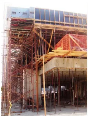
(Figure 1).
Figure 1 – Scaffold system in Fortaleza-Brazil.
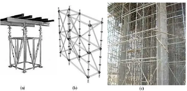
Figure 2 – Welded steel frames.
Figure 3 – Assembled steel scaffolding.
Scaffolding systems can present more than one layer, as illustrated in Figure 3.
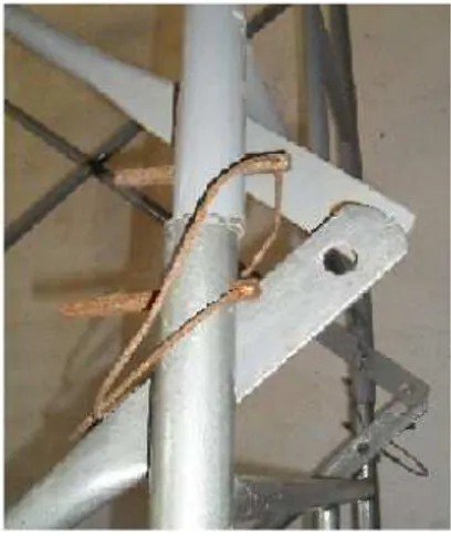
Figure 4 – Connection detail.
3 STRUCTURAL ANALYSIS OF SCAFFOLD SYSTEMS
The safe design of scaffold systems requires the accurate evaluation of the load-carrying capacity of these structures. In this work, scaffold systems are analyzed using the Finite Element Method (FEM). The finite element analyses were performed using ABAQUS (Simulia, 2007), which is a well-known commercial software for structural analysis, and FEMOOP (Martha and Parente, 2002), which an open-source finite element program developed in C++ using Object-Oriented techniques.
Two-dimensional models are used in order to simplify the geometrical modeling and increase the computational efficiency of the finite element analysis. Horizontal and vertical members of the welded frames are modeled by beam elements, while braces are modeled by truss elements. Material nonlinearity was not considered, since members are very slender and buckling and geometric nonlinearity are the main concerns in scaffold design.
A good estimate of the load-carrying capacity of structures with bifurcation buckling can be obtained performing a linearized buckling analysis (Bathe, 1996; Cook et al., 2002). In this procedure, the pre-buckling displacements are neglected and the critical loads and the buckling modes are obtained solving the generalized eigenvalue problem
0 v K
K )
( g , (1)
where K is the (elastic) stiffness matrix, Kg is the geometric (or initial stress) stiffness
matrix, the eigenvalues are related to the critical loads, and the eigenvectors v are the buckling modes. After the solution of the generalized eigenvalue the critical load vector is computed as
f
fcr , (2)
where f is the reference load vector used to compute the geometric stiffness matrix
4 NUMERICAL EXAMPLES
The effect of mesh discretization, scaffold geometry, bracing system, and number of modules (layers) on the critical load and buckling mode will be analyzed using some numerical examples.
4.1 Example 1
This example presents the buckling analyses of two-dimensional modular scaffolding systems. This system is composed of two tubular frames connected with braces (Figure 3b). The connections between horizontal and vertical members and between braces and other members were considered hinged connections. The vertical members were modeled by beam elements, while the other ones were modeled by truss elements. Vertical displacements of the base nodes, as well as the horizontal displacement of the left base node, were constrained in order to eliminate rigid body displacements. The concentrated vertical loads (P) are applied at the top nodes.
The system was modeled with five layers and, in order to study the effect of the mesh discretization on the critical load, the number of elements of each member varied from one to five. It should be noticed that both planes were analyzed to obtain the critical load. Table 1 presents the mechanical properties of the material, while
Table 2 presents the geometric data of the structure. The length of horizontal members is 0.50m for one plane (Plane 1) and 2.50m for the other plane (Plane 2).
Longitudinal Elasticity Modulus (E) 205 GPa
Transversal Elasticity Modulus (G) 78.8462 GPa
Poisson´s Ratio (ν) 0.30
Specific Weight (γ) 77 kN/m³
Table 1 - Mechanical properties of the material (circular tube).
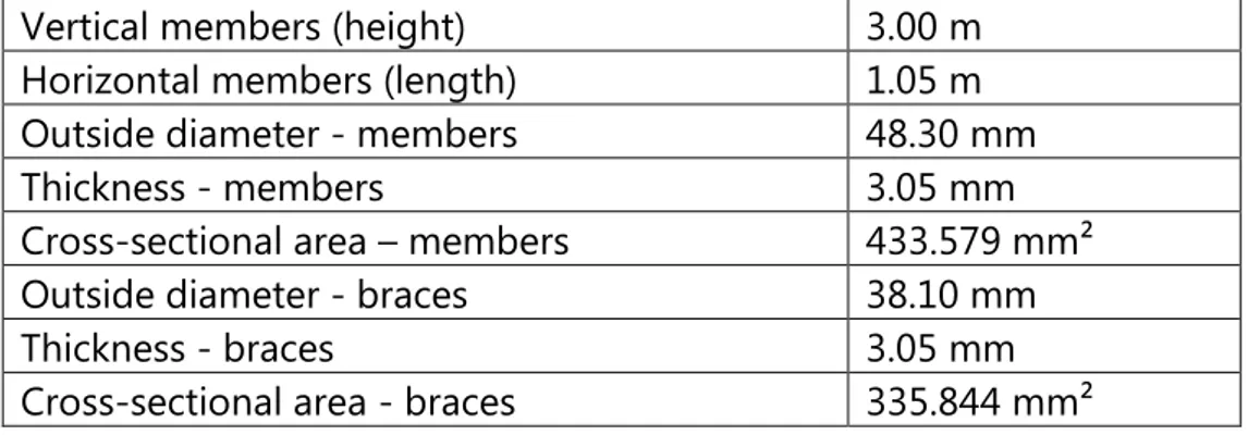
Vertical members (height) 3.00 m
Horizontal members (length) 1.05 m
Outside diameter - members 48.30 mm
Thickness - members 3.05 mm
Cross-sectional area – members 433.579 mm²
Outside diameter - braces 38.10 mm
Thickness - braces 3.05 mm
Cross-sectional area - braces 335.844 mm²
Table 2 – Geometric characteristics of the scaffolding systems (circular tube).
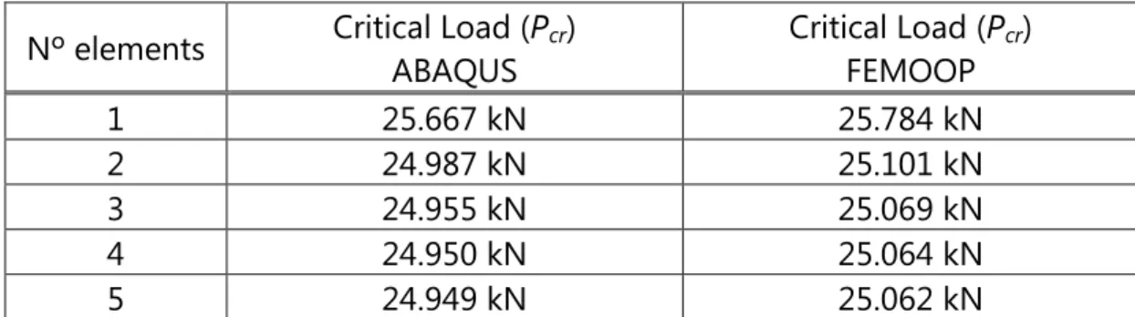
buckling load obtained for the first and second planes was 25.062 kN which suggests that buckling can occur in any direction.
Table 3 also shows that the difference between the critical loads using distinct number of elements is very small. This difference between two and five elements per bar, for example, is less than 0.2% which is insignificant for engineering purposes. For Plane 2, the same behavior is observed. The difference between two and five elements results is also less than 0.2% (Table 4). Furthermore, the results obtained using ABAQUS and FEMOOP have an almost perfect agreement.
Nº elements Critical Load (Pcr) ABAQUS
Critical Load (Pcr)
FEMOOP
1 25.667 kN 25.784 kN
2 24.987 kN 25.101 kN
3 24.955 kN 25.069 kN
4 24.950 kN 25.064 kN
5 24.949 kN 25.062 kN
Table 3 – Critical loads for different discretizations – Plane 1.
Nº elements Critical Load (Pcr) ABAQUS
Critical Load (Pcr)
FEMOOP
1 25.667 kN 25.784 kN
2 24.987 kN 25.101 kN
3 24.955 kN 25.069 kN
4 24.950 kN 25.064 kN
5 24.949 kN 25.062 kN
Table 4 - Critical loads for different discretizations – Plane 2.
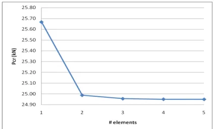
Figure 5 and Figure 6 show the critical loads of the Plane 1 and Plane 2 versus number of elements using ABAQUS with a discretization of 3 beam elements per bar.
Figure 5 – Critical loads versus number of elements (ABAQUS) – Plane 1.
(a) Plane 1 (b) Plane 2
Figure 7 – Buckling modes of Example 1.
4.2 Example 2
This example presents the two-dimensional buckling analysis of the scaffold system presented in Figure 2b. This system was modeled with different number of modules (layers) that varied from one to five, in order to evaluate the effect of the increase of the total height of the scaffold (falsework clearance) on the buckling load. Translations of the base nodes were constrained and concentrated vertical loads (P) were applied at the top nodes. The connections between horizontal and vertical members were modeled as rigid. On the other hand, hinged connections were implicitly used between braces and other members, since braces were modeled by truss elements. Table 1 presents the mechanical properties of the material, while
Table 5 is related to the geometric data of the structure. The distance between vertical members is 2.50m for one plane (Plane 1) and the length of frame is 1.00m for the other plane (Plane 2).
Frame height 2.00 m
X-braces 2.50x0.75m
Outer diameter of frame members 48.30 mm
Wall thickness of frame members 3.05 mm
Wall thickness of X-braces 3.05 mm
Table 5 – Geometric characteristics - Example 2.
The two planes of the scaffold were analyzed using ABAQUS with a discretization of 3 beam elements per bar. The buckling loads for Plane 1 computed for different number of layers are presented in Table 6. It can be noted that the load decreases when the number of layers increases from 1 to 2, but remains almost constant after that.
Layers Critical Load (Pcr)
1 43.768 kN
2 28.738 kN
3 28.347 kN
4 27.497 kN
5 27.264 kN
Table 6 – Buckling loads - Example 2 – Plane 1.
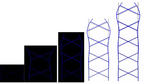
Figure 8 – Buckling modes of Example 2 – Plane 1.
Figure 8 shows the buckling modes of Plane 1 of this scaffold, which are of the non-sway type. It can be noted that the mode changes when the number of layers increases, but these changes are significant only for a small number of layers. For the scaffold with more than 3 layers the variation is small, which is consistent with the results obtained for the buckling load.
the first plane needs to be considered in the stability analysis of this scaffold system.
Layers Critical Load (Pcr) ABAQUS
Critical Load (Pcr)
FEMOOP
1 212.812 kN 213.670 kN
2 212.849 kN 213.280 kN
3 212.849 kN 213.741 kN
4 212.859 kN 213.709 kN
5 212.797 kN 213.916 kN
Table 7 – Buckling loads - Example 2 – Plane 2.
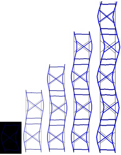
Figure 9 - Buckling modes of Example 2 – Plane 2.
5 CONCLUSIONS
In this work, steel scaffolding systems were analyzed using the Finite Element Method. In the analyses, the well-known commercial software ABAQUS and an open-source finite element program called FEMOOP were used. The effect of mesh discretization, scaffold geometry, bracing system, and number of modules (layers) on the critical load and buckling mode was studied using numerical examples.
It was shown, in the first example, that the mesh discretization was insignificant for the critical load determination. On the other hand, the same example showed the great influence of the braces on the load value and buckling mode. The inclusion of X-braces changed the buckling from a sway mode to a non-sway mode, increasing the buckling load.
The second example studied the effect of the increase of the total height of the scaffold on the buckling load. The critical load remained almost constant (except for one layer), showing little influence of the number of layers, while the buckling modes presented significant changes only for a small number of layers. It should also be observed that the results obtained using ABAQUS were in a very good agreement with the ones obtained using FEMOOP.
It is important to note that actual structures are not composed of perfectly straight members. Moreover, scaffolds are temporary structures assembled in building site leading to misalignment of vertical members. In addition to the main vertical loads, horizontal loads (e.g. wind and concrete vibration) also act on the shoring system. It is well known from the stability theory that geometrical and load imperfections can decrease the load-carrying capacity of perfect structures. Therefore, in the next step of this research nonlinear finite element analyses will be performed in order to study the post-buckling behavior of scaffold systems, including the imperfection sensitivity.
REFERENCES
Chan, S. L., Zhou, Z. H., Chen, W. F., Peng, J. L., and Pan, A. D., Stability analysis of semirigid steel scaffolding. Engineering Structures, 17:568–574, 1995.
Chan, S. L., Huang, H. Y., and Fang, L. X., Advanced analysis of imperfect portal frames with semirigid base connections. Journal of Engineering Mechanics, 131:633–640, 2005.
Chandrangsu, T., and Rasmussen, K. J. R., Review of Past Research on Scaffold Systems, Research Report No. R905, 2009.
Cook, R., Malkus, D., Plesha, M.; and de Witt, R. J., Concepts and Applications of Finite Element Analysis. Fourth edition, John Wiley & Sons, 2002.
Hadipriono, F. C., and Wang, H. K. Analysis of causes of falsework failures in concrete structures. Journal of Construction Engineering and Management, 112:112–121, 1986.
Engineering, 11:369–382, 2008.
Martha, L. F.; Parente Jr., E., An Object-Oriented Framework for Finite Element Programming. Proceedings of Fifth World Congress on Computational Mechanics (WCCM V), Vienna: 2002, pp. 1–10, 2002.
Peng, J. L., Pan, A. D. E., Rosowsky, D. V., Chen, W. F., Yen, T., and Chan, S. L., High clearance scaffold systems during constructions – I, Structural modeling and modes of failure. Engineering Structures, 18:247–25, 1996.
Peng, J. L., Pan, A. D. E., Chen, W. F., Yen, T., and Chan, S. L., Structural modeling and analysis of modular falsework systems. Journal of Structural Engineering, 123:1245– 1251, 1997.
Peng, J. L., Stability analyses and design recommendations for practical shoring systems during construction. Journal of Construction Engineering and Management, 128:536–544, 2002.
Peng, J. L., Structural modeling and design considerations for double-layer shoring systems. Journal of Construction Engineering and Management, 130:368–377, 2004. Peng, J. L., Chan, S. L., and Wu, C. L., Effects of geometrical shape and incremental
loads on scaffold systems. Journal of Constructional Steel Research, 63:448–459, 2007.
Peng, J. L., Chen, K. G., Chan, S. L., and Chen, W. T., Experimental and analytical studies on steel scaffolds under eccentric loads. Journal of Constructional Steel Research, 65:422–435, 2009a.
Peng, J. L., Yen, T., Kuo, C. C., and Chan, S. L., Analytical and experimental bearing capacities of systems scaffolds. Journal of Zheijiang University Science A, 10:82–92, 2009b.
Simulia. ABAQUS User’s Manual, Version 6.7, 2007.
Wardhana, K., and Hadipriono, F. C., Study on recent building failures in the United States. Journal of Performance of Constructed Facilities, 17:151–158, 2003.
Wessner, L. B., and Jones, H. L., Experimental and analytical capacity of frame scaffolding. Engineering Structures, 23:592–599, 2001.
Yu, W. K., Chung, K. F., and Chan, S. L., Structural instability of multi-storey door-type modular steel scaffolds. Engineering Structures, 26:867–881, 2004.
Yu, W. K., Chung, K. F., and Chan, S. L., Axial buckling of bamboo columns in bamboo scaffolds. Engineering Structures, 27:61–73, 2005.