TWO EXPERIMENTAL FISH AGGREGATING SYSTEMS (FADs)
IN THE AEGEAN SEA: THEIR DESIGN AND APPLICATION*
Aytaç Özgül**, Altan Lök and F. Ozan Düzbastılar
Ege University, Faculty of Fisheries (Izmir-Turkey 35100, Bornova-Izmir, Turkey)
**Corresponding author: [email protected]
A
B S T R A C TTwo steel spar buoys were constructed and moored in 50 and 100 m deep of water in the Aegean Sea to support recreational fisheries. The first FAD was deployed at coordinates 38°01´48´´N 26°58´02´´E and at a distance of 3 nautical miles from the shoreline. The other FAD was moored at 1.1 nautical miles from the shoreline at coordinates 38°03´11´´N; 26°59´01´´E. An anchor (1.2x1.2x0.8 m3) weighing approximate 2.76 metric ton, made of reinforced concrete, was used to hold a FAD weighing approximate 1.5 metric ton. Hardware and connections of FADs, ropes, mooring calculation and anchor design were made. The interaction between the forces of wave and current and FADs in those waters was investigated. In the experiment, all forces (drag force, buoyancy force etc.) acting on FADs were calculated. It is proposed that the construction of the FADs should take the following design criteria into consideration: wave and current, forces related to the FADs, deployment depth, mooring hardware and ropes. This knowledge provides an important reference for stakeholders performing projects aiming to increase the performance and service life FADs.
R
E S U M ODuas bóias de aço spar foram construídas e ancoradas em 50 e 100 m de profundidade nas águas do Mar Egeu para dar apoio à pesca recreativa. O primeiro FAD foi implantado nas coordenadas 38°01'48''N 26°58'02''E, a uma distância de 3 milhas náuticas da costa. O outro ficou ancorado a 1,1 milha náutica da costa nas coordenadas 38°03'11''N; 26°59'01''E. Uma âncora (1.2x1.2x0.8 m3), pesando aproximadamente 2,76 toneladas, feita de concreto armado, foi usada para prender um FAD de peso aproximado de 1,5 toneladas. Foram realizados cálculos para determinação das conexões dos FADs, dos cabos e da ancoragem. A interação entre as forças de ondas e correntes com os FADs foi também investigada. No experimento, todas as forças (força de arrasto, força de empuxo, etc) atuantes sobre os FADs foram calculadas. É proposto que para a construção dos FADs deverão ser levados em consideração os seguintes fatores: ondas e correntes, forças relacionadas com os FADs, profundidade de implantação, sistema computacional dos moorings e cordas de amarração. Esse conhecimento proporcionará referência importante para os interessados em realizar projetos que visem aumentar o desempenho e a vida útil dos FADs.
Descriptors: Fish aggregating system, FADs, Wave current and effects, Aegean Sea.
Descritores: Sistema de concentração de peixes, FADs, Efeito das correntes e ondas, Mar Egeu.
I
NTRODUCTIONAn artificial reef has recently been identified as "any structure that people build or
place on the seafloor, in the water column or floating on the sea surface for the purpose of either creating a new attraction for scuba divers or to concentrate or attract plants or animals for the purpose of fishing" by
__________
(*) Paper presented at the 9th CARAH – International Conference on
Artificial Reefs and Related Aquatic Habitats on 8-13 November, Curitiba, PR, Brazil.
minimal fishing effort (KOJIMA, 1956; MORALES-NIN et al., 2000). Although FADs have for many years been defined basically as objects placed in the seas to aggregate fish for capture, according to the literature the first commercial FADs were moored in the seas off the Philippines at the beginning of the 1970s (KIHARA, 1981; DEMPSTER; TAQUET, 2004). Even though fishermen have been using FADs for some centuries in various parts of the world, researchers have only started to investigate them in the last 50 years (RELINI et al., 1995).
It was against this background that the experimental use of anchored FADs was planned in the Aegean Sea. Two steel surface spar buoys were designed and constructed to aggregate fish. For this study, we designed a FAD system capable of remaining stable in the face of wave, current and wind forces. We used wave data from ÖZHAN; ABDALLA (2002) obtained at the station off Ku adası, Aegean Sea. Current data were obtained from a current meter deployed at 50 m water depth. We used wind data from the nearest point to the FADs position, of the Turkish State Meteorological Service of the Republic of Turkey´s Ministry of the Environment and Forestry. The main goal of the study was to design a stable FAD system with respect to interactions between all the forces (wave force, current force, wind force, etc.) and the floating reef body. Then the hardware and connections of the FADs, ropes, mooring calculations and anchor design were prepared. As well as the aspects of the engineering design, the shape of each spar buoy was also designed to attract surface migratory fish by changing the pattern of the current around the floating reef body.
M
ATERIAL ANDM
ETHODSStudy Site
The FADs were deployed at a distance of 1.1 to 3 nautical miles offshore and at depths of 50 to 100 meters, respectively, in waters of the Gulf of Ku adası (Fig. 1).
The site had been used as an experimental artificial reef area since 1998. Two steel spar buoys (FAD units) were moored there in 2008 to assist the R/V EGESUF (26.8 m length, ~500 HP engine).
Spar Buoys
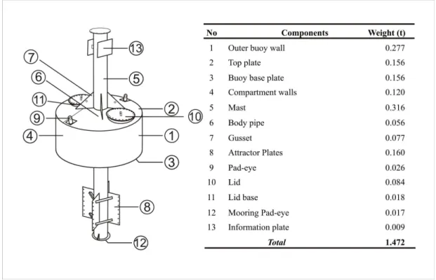
A FAD consists of two main parts: the buoy and the pedestal (Fig. 2). The spar buoys (the buoys of the FADs) have three separate float-tanks to prevent sinking. All the components of the FADs were made of steel protected by anti-corrosive paint. The upper part of the mast and spar buoy was painted yellow to ensure high visibility for shipping. The bottom of the buoy and the lower part of the mast were painted blue. Cathodic protection using galvanized steel was applied to the underwater parts of the buoy (FAD) to prevent electro-chemical corrosion. Two horizontal lids were constructed on the body of the spar buoy to allow the periodic maintenance of the inner parts. An inclined upper surface was designed to drain water off the buoys. Pad-eyes were fitted to the upper and lower parts of the buoys for the mooring of fishing vessels and as attractors. Four rectangular steel panels were welded onto the lower part of the mast of the FADs to create vortices and change the current pattern.
Fig. 2. Illustration of FAD.
Mooring
Mooring hardware and connections consisted of buoyant and sinking ropes, a chain, connections, and an anchor (Table 1). The spar buoy was connected to an anchor by a combination of chain, sinking rope, buoyant rope and hardware (shackle, swivel, rope connector etc.) connections. The anchor, made of reinforced concrete, weighed approximately 2.76 metric tons. The sinking rope (Ø32, lead core polypropylene rope) was used following the chain rope so as not to interfere with shipping. The third and fourth parts of the rope combination were of buoyant rope (polypropylene) (Ø32) and chain, respectively (Fig. 3). The length of the whole rope was 20% greater than the installation depth to reduce the lifting effect of the rope on the anchor. Further, the ratio of sinking rope to buoyant rope was 30/70.
Table 1. Combination of chain and ropes in mooring system.
Wave Data and Calculation of Water Particle Velocity
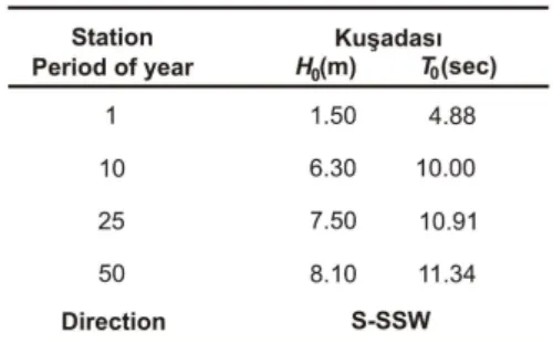
To enable us to design a stable FAD in the face of the wave force, wave data were obtained from the ’’Atlas of Wind and Deepwater Wave Climate of the Turkish Coast’’ (ÖZHAN; ABDALLA, 2002). Wind data and, hence, wave conditions were provided by the synoptic weather charts of ÖZHAN; ABDALLA (2002). The approach to wave forecasting is based on the 10-year-results of wave observations. Deepwater-significant wave heights (H0) for various
periods of recurrence (1, 10, 25 and 50 years as shown in Table 2) are presented in the atlas. In the study the 25-year recurrence period was used.
The horizontal velocity of the water particles (uwave) towards the underwater section of the spar
buoys was calculated using Eq. (1) based on the linear wave theory (where k is the wave number, σ a wave angular frequency, z the depth at which the particle velocity is calculated, h the water depth, H the wave height and T the wave period). In this equation, σ is a wave angular frequency that is equal to 2π/T (DEAN; DALRYMPLE, 2000; SORENSEN, 2006).
Table 2. Wave data of recurrence periods of 1, 10, 25, and 50 years for Ku adası (ÖZHAN; ABDALLA, 2002).
Current Data
A current meter (Acoustic Doppler Current Profiler, 600 kHz) was deployed at 50 m water depth to measure current velocity (ucurrent) and direction. The
maximum current velocity was used for both installation depths. A stainless steel cage was used to hold and protect the current meter.
Wind Data
Wind speed measurement data were obtained from the observation station nearest to the study site. The maximum wind speed (uair) was
observed as 107.3 km/h (01.31.2003), according to the observation results of the Turkish National Meteorological Service.
Calculation of Combined Forces (FC)
The body of the FAD is subject to wave, current and wind forces. The same direction was assumed for all these forces to estimate their total resulting impact on the FAD´s body. Those forces are defined by Eq. (2) where FD is the drag force, CD the
drag coefficient, γseawater the density of sea water (or γair
the density of air), u the water particle velocity (or
ucurrent the current velocity and uair the wind speed),
and Ay the projected cross-sectional area.
(2)
In the stability analysis, FC must be equal to
FF (friction force) for the equilibrium to be that shown
in Eq. (3).
(3)
R
ESULTSStudy Site and Application
The site selection criteria to deploy FADs can be summarized in six categories:
(1) Feasible sea bottom structure for the deployment of FADs;
(2) This site had been used as an artificial reef area for the last decade;
(3) The project was supported by the local municipality;
(4) Fishing activity and maritime traffic at a low level; (5) Logistic opportunity;
(6) Researchers had experience of the reef site.
In view of the above circumstances, two spar buoys were transported by R/V EGESÜF and moored at two different water depths. The coordinates of these depths were recorded by GPS before deployment. The spar buoys were lifted and deployed by a winch with a maximum capacity of around 8 metric tons.
Current Measurement
During the observation periods (30 days in spring and 60 days in summer), the maximum and the minimum current velocity were recorded as 1259 mm/s and 1 m/s, respectively, between the 0-4 m depths ranges. The average current speed for all depths from the surface to 48 m water depth is shown in Figure 4.
Calculation of Force and Stability Analysis
The drag force and vertical forces (weight of FADs and anchor; WFAD and Wanchor, buoyancy force
of FADs and anchor; FB1 and FB2, vertical net force;
N) acting on the spar buoy were estimated. To
calculate the forces of wind, waves and currents, drag coefficients (CD), dimensions of spar buoys, and
horizontal velocities (uair: 29.80 m/s, uwave: 2.36 m/s,
ucurrent: 1.26 m/s) were obtained (Table 3). Wind forces
were calculated for the upper parts of the FAD. Components of wind force, wave force and current force were calculated as given in Table 3 and Figure 5. According to stability analysis the magnitude of the combined forces is lower than the resisting force. The weight of the anchor (Wanchor) was 2.76 t, although its
design weight (Wdesign anchor) was 2.63 t. The friction
force (FF) was higher than the mobilizing forces,
Fig. 4. Current data obtained from current meter.
Table 3. Approximate CD values, dimensions and horizontal forces for upper and lower parts of a spar buoy.
D
ISCUSSION ANDC
ONCLUSIONThis study sought to design FAD systems before deployment offshore to avoid possible mooring failures. The main forces - excluding the lifting force - acting on a FAD unit were calculated. By the end of the study, it had become apparent that the weight of the anchor was sufficient for safe deployment. To carry out stability analysis, the resisting and mobilizing forces and related coefficients were calculated. This quantitative study was undertaken with limited wave current and wind data and without performing any laboratory experiments. However, we have observed both FAD systems as stable for approximately 2 years following the deployment process. Hardware and connections were selected to be sufficiently strong to resist the loads caused by external forces. Similar numerical studies (SU et al., 2008; DÜZBASTILAR AND ENTÜRK, 2009) and hydraulic experiments (INGSRISAWANG et al., 1995; 1999; DÜZBASTILAR, et al., 2006; RECIO AND OUMERACI, 2007) and on-site research have been undertaken to understand and evaluate the mechanisms and effects of waves and currents on the benthic reefs. However, no information on the subject relative to FADs has so far been reported. To provide long service life for FADs deployed in the Aegean Sea, all the components of the units must be evaluated in view of the environmental conditions and considering the worse possible scenario. Even though taking the worst possible sea conditions into consideration, the actual weight of the anchor was greater than its design weight. When undertaking FAD design, decision-makers must take into account wave, current and wind effects and these should be evaluated using the stability equation before the deployment of the FADs.
A
CKNOWLEDGEMENTSThis work has been funded by The Scientific and Technological Research Council of Turkey. The authors are also grateful to the captain and crew of R/V EGESÜF for the sea cruises.
R
EFERENCESANDALORO, F.; CAMPO, D.; CASTRIOTA, L.; SINOPOLI, M. Annual trend of fish assemblages associated with FADs in the southern Tyrrhenian Sea. Journal of Applied Ichthyology, v. 23, p. 258-263, 2007.
DEAN, R. G.; DALRYMPLE, R. A. Water wave mechanics for engineers and scientists. Advanced Series on Ocean Engineering, v. 2. 2000. 351p.
DEMPSTER, T.; TAQUET, M. Fish aggregation device (FAD) research: gaps in current knowledge and future directions for ecological studies. Reviews in Fish Biology and Fisheries, v. 14, p. 21-42, 2004.
DEMPSTER, T. Temporal variability of pelagic fish assemblages around fish aggregation devices: biological and physical influences. Journal of Fish Biology, v. 66, p. 1237-1260, 2005.
DÜZBASTILAR, F. O.; LÖK, A.; ULA , A.; METIN, C. Recent developments on artificial reef applications in Turkey: Hydraulic experiments. Bulletin of Marine Science, v. 78 (1), p. 195-202, 2006.
DÜZBASTILAR, F. O.; ENTÜRK, U. Determining the weights of two types of artificial reefs required to resist wave action in different water depths and bottom slopes. Ocean Engineering, v. 36, (12-13), p. 900–913, 2009. FLUENT. Fluent Inc., FLUENT6.3.26 User Manual. 2007. INGSRISAWANG, V.; BAN, M.; KIMURA, H.
Comparative study on the sinking of artificial reefs by local scour between laboratory and field experiments. Fisheries Engineering, v. 32 (2), p. 95-103, 1995. INGSRISAWANG, V.; KIMURA, H.; BAN, M. Experiment
on local scour and embedment of artificial reef models due to wave action in shallow water area. Thai Marine Fisheries Research Bulletin, v. 7, p. 26-34, 1999. KOJIMA, S. Fishing for dolphins in the Western part of the
Japan Sea - II. Why do the fish take shelter under floating materials? Bull. Jap. Soc. Sci. Fish. 21 (10), 1049-105, 1956.
MORALES-NIN, B.; CANNIZZARO, L.; MASSUTI, E.; POTOSCHI, A.; ANDALORO, F. An overview of the FADs fishery in the Mediterranean Sea. In: Le Gall, J.-Y., Cayre, P. and Taquet, M. (eds.), Pe^che Thoniere et Dispositifs de Concentration de Poisons. Ed. Ifremer, Actes Colloq. v. 28, p. 184-207, 2000.
ÖZHAN, E.; ABDALLA, S. Wind and Deep Water Wave Atlas for Turkish Coast in Turkish, Kıyı Alanları Yönetimi Türk Milli Komitesi (MEDCOAST), Orta Doğu Teknik Üniversitesi, Ankara, 445pp. 2002 RECIO, J.; OUMERACI, H. Effect of deformations on the
hydraulic stability of coastal structures made of geotextile sand containers. Geotextiles and Geomembranes 25, 278-292. 2007.
RELINI M.; TORCHIA, G.; RELINI, G. The role of a FAD in the variation of fish assemblages on the Loano Artificial Reef (Ligurian Sea NW-Mediterranean). Proceedings ECOSET 95. Japan International Marine Science and Technology Federation, v. 1, p. 1-5, 1995. SORENSEN, R. M. Basic Coastal Engineering, 3rd edition,
2006, 324 p.
SU, D. T.; LIU, T. L.; OU, C. H. Numerical investigation into effects of seabed topography on flows in and around artificial reefs. Fisheries Science, v. 74, p. 236-254, 2008.
http://www.gbrmpa.gov.au/corp_site/management/eim/guidel ines_artificial_reefs#What%20are%20Artificial%20Reef s. Guidelines for the Management of Artificial Reefs in the Great Barrier Reef Marine Park. What are artificial reefs?