Article
Studies on the Hall-Heroult Aluminum Electrowinning Process
Shiva Prasad
Departamento de Engenharia Química, CCT, Universidade Federal da Paraíba, CP 10108, 58109-970, Campina Grande - PB, Brazil
Estudos da eletrólise da criolita-alumina fundida mostraram que nas melhores condições de operação, a 960oC, a eficiência energética é de apenas 33%. Encontrou-se que para o funcionamento
estável da célula a 3% de alumina a relação NaF/AlF3, em peso-percentual, deve ser no mínimo
1,11. Encontrou-se ainda que a fileira de ânodos posicionada junto a “down-stream” está sujeita a uma turbulência mais intensa, de modo que elevando-se o nível desta fileira em 4 cm, resulta em uma diminuição no número de “burnoffs”. A seleção cuidadosa do material de revestimento da célula aumentou sua vida útil. A estabilidade da interface alumínio-banho é um dos principais fatores que afetam a eficiência de corrente. Uma modificação na célula foi proposta para se ter uma melhor estabilidade na interface alumínio-banho. O novo desenho proposto para a célula permite uma redução da distância cátodo-ânodo, diminuindo a voltagem e consequentemente, melhorando a eficiência anódica.
Studies on the electrolysis of cryolite-alumina melt showed that even the best equipped smelter, functioning at 960 oC, has only 33% energy efficiency. For stable functioning of the
smelter at 3% alumina the minimum wt% ratio NaF/AlF3 was found to be 1.11. The anodes located
on down-stream row were found to face more turbulence; raising their level by 4 cm resulted in decreasing the number of burnoffs. A careful selection of potlining material improved the pot life. The stability of the aluminum-bath interface is one of the major factors affecting the current efficiency. An improved cell design has been proposed to achieve the ultimate aluminum-bath interface stability. The proposed cell design should allow a reduction of the cathode-to-anode distance producing a lower voltage and improving the power efficiency.
Keywords: aluminum electrowinning, Hall-Heroult process, electroreduction
Printed in Brazil 0103 - 5053 $6.00+0.00
Introduction
The commercial production of metallic aluminum started in 1889 with electrolysis of cryolite-alumina melt by the Hall-Heroult process. Apart from the technological refinements made since, the electrolytic aluminum process remains basically the same, as it was 110 years ago1.
Nu-merous alternatives to the H-H process have been consid-ered over the years, attempting to reduce the cost of the metal, but no one could replace it due to technical prob-lems2. The changing economic conditions make the
devel-opment of low-cost cells vital for the industry. Potential improvements to the process that have received consider-able attention in recent years are: increase in current effi-ciency, development of nonconsumable anodes and more resistant potlining, reduction in energy losses, and optimi-zation of the bath composition. Results of a modest at-tempt by the author in some of these areas are given in this paper. A long involvement of the author in the areas such as
electrodeposition of alloys3, electroreduction of aluminum4
and chemistry of bauxite5; and a recent integration
pro-gram with Alumar (UFPB-PRODENGE/ ALUMAR) has helped to conclude this work. The work was realized by the author in the premises of Alumar.
Basics and bath chemistry of the Hall-Heroult process
certain additions are made and a typical electrolysis medium also contains excess AlF3 (10-12%) and CaF2
(4-6%) along with a regular feeding of alumina. The addi-tives increase the conductivity of the medium and lower the melting point of the cryolite from 1011 to 920-970oC
resulting in decrease in energy consumption. But the ad-ditives cause a decrease in the solubility of alumina (from 15-wt% to about 6-wt%) and this limits the total concen-tration. Alumina is added to the cell periodically because during the electrolysis its concentration drops, and if it is allowed to fall below about 2%, the electrolysis cell un-dergoes a sudden and major operational failure known as an ‘anode effect’. The cell voltage increases rapidly from -4.5 V to a value in the range of -40 to -60 V. Overfeeding of the cell with alumina causes formation of a sludge under the molten aluminum pad decreasing the electrical con-ductivity and resulting in a ‘sick pot’. The optimum cur-rent density is around 1 A cm-2 with a total cell current of
150-300 kA and a cell voltage -4.0 to -4.5 V. A typical cell house will contain about 200 cells arranged in series on two lines. All cell houses have a strong magnetic field due to the large currents used. The field can produce turbu-lence at the aluminum/electrolyte interface if the bus bars are not arranged in a compensating manner. Aluminum is probably present as a mixture of several oxy-fluoride spe-cies in the electrolyte. Therefore the exact chemistry of the system is not known. However, the cathode reaction is reduction of Al(III) species to the metal forming a pool of liquid aluminum at the bottom of the pot and acting as cathode. The anode reaction should be the oxidation of oxide ion to oxygen, but it is difficult to find an anode material which is inert under the aggressive conditions of electrolysis. Hence the electrolysis has always been run
with consumable carbon anodes so that the overall cell reaction is:
2 Al2O3 + 3 C = 4 Al + 3 CO2 (1)
Some undesired reactions also take place in the pot, which are mainly responsible for the loss of current effi-ciency. The aluminum metal may react with components of the bath to produce dissolved metal in the bath. The main reactions forming the dissolved metal are:
3 NaF(bath) + Al(Al pad) 3 Na(bath and Al pad)+
+AlF3(bath) (2)
AlF3(bath) + 2 Al(Al pad) 3 AlF(bath) (3)
The equilibrium (2) produces a concentration of so-dium dissolved in both the aluminum and the bath. This concentration increases as the NaF:AlF3 ratio at the
alu-minum-bath interface increases. At the same time equilib-rium (3) produces an interfacial concentration of monova-lent aluminum species in the bath. This concentration in-creases as the NaF:AlF3 ratio at the interface decreases.
Equilibria (2) and (3) shift to the right with increasing temperatures producing higher interfacial concentrations of reduced species leading to lower current efficiency6.
Since sodium is the predominant dissolved metal a low NaF:AlF3 ratio promotes higher current efficiencies6.
The reactions oxidizing the dissolved metals (Na & AlF) are:
6 Na(bath) + 3 CO2(g) + 2 AlF3(bath) →
Al2O3(bath) + 6 NaF(bath) + 3 CO(g) (4)
3 AlF(bath) + 3 CO2(g) → AlF3(bath) +
Al2O3(bath) + 3 CO(g) (5)
For reactions (2) through (5) to take place, AlF3 must
Crust breaker
Stud
Electrolyte
Insulation
Therm al insulation Current supply
Feeder
Air cylinder
Alumina
Fume collection Anode rods
Removable Clamp
covers
Alumina crust
Frozen ledge Carbon block
Carbon lining Steel shell
Carbon anode
Current collection bar
Carbon lining
Molten a luminium
diffuse in through the cathode boundary layer. NaF and dissolved metal must diffuse out. Na+ is transported in by
the current but does not discharge because aluminum from AlF3 discharges at a lower potential than sodium. The
result is a higher NaF:AlF3 ratio at the interface than in the bulk7. Thicker boundary layers decrease mass transport
raising both NaF and Na concentrations at the interface, but the thicker boundary layer lets less dissolved metal to diffuse out. Measurements have shown that convective transport of dissolved metal through the bath and its reac-tion with CO2 are fast. Diffusion of dissolved metal through the boundary layer at the cathode is the slow or rate limit-ing step. For a given boundary layer thickness, the total amount of dissolved metal diffusing out is proportional to the cathode area. Hence a high cathode current density improves the current efficiency because more aluminum is made compared with the dissolved metal entering the bath to be reoxidized6.
Impurities may also enter the bath, mainly with alumina and carbon anodes, participating in reactions and decreas-ing the current efficiency. Multivalent impurities, in the form of anionic complexes, of Fe3+, Ga3+, Ni3+, V5+ and
Cr6+ diffuse into the boundary layer and are reduced to a
lower valence state as they meet dissolved metal diffusing out8. A fraction of each impurity continues on to be fully
reduced and alloy with the aluminum. The rest diffuses out at the boundary layer and is transported by convection to the vicinity of the anode where each is reoxidized by CO2 forming CO and oxidized impurity. Convection takes these reoxidized impurities back to the cathode to repeat the cycle. Transport through the cathode boundary layer remains the rate controlling step, but the impurities diffusing into the boundary layer reduce the distance through which the dis-solved metal must diffuse. The lowering of current efficiency by impurities in the bath has been confirmed experimently6.
Experimental
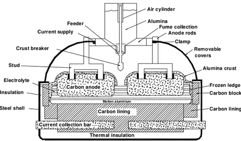
The work was carried out on electrolysis pots made of steel box (9.96 m length, 3.97 m breadth, 1.175 m height) lined with a refractory, thermal insulator (Figure 1). The base of the pot was lined with prebaked carbon blocks and the sides with partially graphitized anthracite in coal-tar pitch. Two rows of 12 anodes, each of prebaked carbon blocks manufactured from coke and a pitch binder, were used in each pot. Each anode was of 154.94 cm length, 72.07 cm width and 61.91 cm height. The gap between two anodes was 3.78 cm and the aisle width: end 33.97 cm, side 21.91 cm, and center 16.51 cm. The cell functioned at about 4.45 V, 216 kA and 960 oC with a metal level of 10 cm and a bath
level of 19 cm. The bath composition was 11.8 wt% excess
AlF3, 5.5 wt% CaF2, 3% Al2O3 and the rest of cryolite. Three point feeders in each pot allowed alumina feeding.
The process was controlled by a computer system us-ing sophisticated software. The control and decision making was based on voltage comparison. The overall control strategy included the control of the variables that change in the short-term (alumina concentration, cell volt-age, inter-electrode separation), making allowance for slowly changing variables but having an overriding sys-tem for the abnormalities (sludging, anode effects, short-circuited anodes, accumulation of carbon dust in the bath). The control system also provided printed as well as spoken (speechmaker) messages.
The control problem in the cells is very complex. The cell variables are inter-related in such a complex way that decision-making is a difficult task. For example, the change in cell temperature can be attributed to any of the follow-ing parameters: cell voltage, cell current, feed cycle, alu-mina concentration, depth of metal pad, ledge formation, frequency and duration of anode effects, amount of alu-mina covering over the anodes, metal tapping, anode change, etc. The temperature of the cells was measured manually by an immersion type metal clad thermocouple and corrective measures were taken after analyzing differ-ent parameters. The bath and metal pad levels were mea-sured by specific measuring rods. The levels were main-tained to predetermined values. The bath samples were taken out for monitoring the ratio of sodium fluoride to aluminum fluoride, and the alumina concentration. The successive alkaline (KOH) and acidic (HCl) titrimetric method2d was used for determination of the bath ratio and
the LECO technique9 for determination of alumina
con-tents. A series of experiments was performed to determine the minimum bath ratio for 3% alumina concentration and also to study the alumina solubility.
connections + strap to bus bar welding joints + riser- alumi-num to alumialumi-num-connections + riser flexibles to anode bus bar welding joints) and total cathode drop (from Al-metal pad up to the next anode bus bar).
never obtained. It is reported that the best-equipped smelters have hit a ceiling of 95-96% current efficiency11. The
prin-cipal loss mechanism involves reactions (2) through (5) along with the participation of impurities in the oxidation reduction reactions6. The four major factors which can
af-fect these reactions, and hence the current efficiency, should be bath temperature, bath composition, cathode current den-sity and the stability of the aluminum-bath interface.
Bath chemistry and bath temperature set the driving force at the aluminum-bath interface to transport dissolved metal into the bath where it is reoxidized. A stable alumi-num-bath interface also reduces electrical shorting. An unstable metal pad results from the motor action produced by horizontal currents in the aluminum interacting with the vertical magnetic field of the cell2c. Horizontal
cur-rents are caused primarily by undissolved alumina sludge formed under the aluminum and to a degree by poor anode current balance. The sludge forms in the bath-filled capil-lary between the aluminum and the carbon bottom of the cell. When the bottom is wetted by aluminum, there is no capillary and hence no place for sludge to form and desta-bilize the cell. There have been reports that TiB2
compos-ite coatings applied to the carbon cathode increase the cell’s stability and increase current efficiency by one to four percent12,13. But no mechanism is presented to
ex-plain this improvement. A likely mechanism is being pro-posed. The TiB2 composite coating improved the wetting characteristic of the carbon cathode resulting in an alumi-num-wetted surface, which in turn improved the stability and current efficiency of the cell.
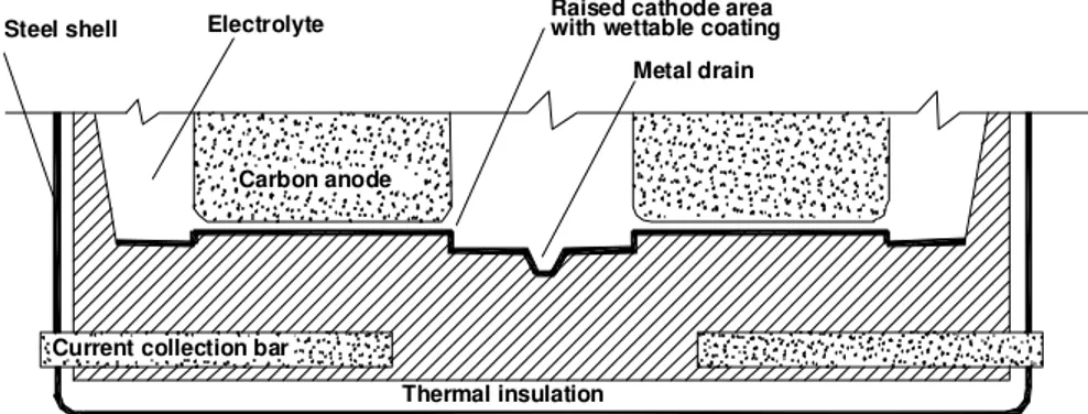
An improved cell design for stable molten aluminum surface is being proposed here (Figure 2). In place of a plane carbon cathode there should be a raised area of alu-minum-wetted material under each anode. The top of the raised area should have the same shape and size as the bottom of the anode on it. Molten aluminum deposited onto the raised surface will drain down the sides of the wetted block into channels leading to an aluminum
Table 1. Voltage (-mV) distribution observed in the Hall-Herault cells.
Reversible cell potential 1,225 Overvoltages (anode = 510, cathode = 80) 590
iR drop in electrodes (anode = 420, cathode = 680) 1,100
iR drop in electrolyte 1,535
Total cell voltage (-mV) 4, 450
Thermal insulation Steel shell
Carbon anode
Current collection bar
Electrolyte Raised cathode areawith wettable coating
Metal drain
Figure 2. Schematic view of the conceptual cathode design.
Results and Discussion
Energy consumption
The voltage drops observed in the cell are demonstrated in Table 1 and the energy consumption was found to be 14.0 k W h kg-1 Al. If the energy required to maintain the
cell at 960oC is taken into account, the energy efficiency
of the process was only 33%. The iR drops in the cell are large, which may be ascribed to the low conductivity of carbon, a large interelectrode gap, gas bubbles on the an-ode, and undissolved alumina. The former three are mainly related to the consumable anode. Some work has been carried out in China10 to decrease the anodic overvoltage
by doping the anode with a lithium salt.
The current efficiency of the plant under our observation reached 95%. Impurities, which show variable oxidation states such as P and V, are particularly bad as they can be reduced at the cathode and then reoxidized at the anode, consuming current without producing any metal. Our plant faced such problem, decreasing CE from 95% to 94%, when the pots were fed with alumina from an altered refinery process.
Current efficiency
collection area. The thin film of aluminum on the raised surfaces will not be affected by electromagnetic forces. There will be no waves, swirls and electrical shorting. An-ode and cathAn-ode current densities will be essentially the same. A maximum cathode boundary layer will form pro-ducing the maximum current efficiency consistent with the bath composition, temperature and current density. Besides this, the stable aluminum interface will allow a reduction of the cathode-to-anode distance producing a lower cell voltage. This combined with the higher current efficiency will improve the power efficiency. The improve-ment can be optimized further by simulation of current distribution and can be estimated quantitatively only by performing experiments on the modified cell as the pro-cess includes many highly coupled phenomena. The re-sults of such study would be published only after the con-clusion of the next stage of the project.
Bath composition
Molten cryolite, having a high solubility for alumina, is the major component of the bath. The most common additives are AlF3 and CaF2, which serve to reduce the liquidus temperature. Haupin14 has excellently reviewed
the effect of additives on the properties of baths. The ob-jectives in changing the bath composition are to lower the temperature, raise the current efficiency, lower the volt-age, maintain operating stability and decreasing emissions while maintaining proper ledge and not generating sludge under the metal pad. Even a slight change in bath compo-sition may upset the proper functioning of the cell. A se-ries of experiments was performed to determine the mini-mum possible bath ratio for 3% alumina concentration. It was found that a bath ratio (Wt% ratio NaF/AlF3) lower
than 1.11 was detrimental to operational stability, prob-ably due to a decrease in solubility of alumina resulting in the formation of insoluble agglomerates. Cells exploiting high AlF3 baths require maintaining an almost constant
bath composition15. They require a careful feeding of
alu-mina controlled by computer systems using sophisticated software, such as the Track System16 and other
modifica-tions, which are under test in Alumar. Alumina concentra-tion is usually kept in the range of 2-5%. Lower concen-trations have risk of anode effect while higher concentra-tions have risk of sludge formation. Production results have revealed that operating with low bath ratios contribute to high current efficiency. Control of granular distribution of the feed alumina is also very important. As for example, feeding 90% fraction of +325 mesh alumina in place of 82% decreased the frequency of anode effects in our test cells.
It has become widely appreciated in recent years with the more open market in alumina supplies that the physi-cal nature of alumina used in aluminum reduction plants can greatly influence the operation of the cells17-19. The
author has recently started a research work at Alumar to study the impact of the physical nature and mode of feed-ing of alumina on the functionfeed-ing of the cell. Preliminary results have shown that the dissolution of alumina is a two step process: a part of the batch becomes dispersed and dissolves rapidly (within one minute) while the rest forms aggregates that dissolve at a significantly slower rate. The portion that dissolves rapidly increases with decreasing alumina batch size, increasing convection in the bath and turbulence on the bath surface.
The cathode lining
Both the cryolite-alumina melt and liquid aluminum are extremely corrosive materials and very few materials can withstand their corrosive action at 1000oC. Carbons,
graphite and refractory borides (particularly TiB2) are the
only electronic conductor materials that are satisfactory. Preformed blocks of semi-graphitized carbon are generally used for the lining. Carefully selected quality materials are essential for long life of the pots. In the plant under our
2 3 5 0 2 4 0 0 2 4 5 0 2 5 0 0 2 5 5 0 2 6 0 0 2 6 5 0 2 7 0 0 2 7 5 0 2 8 0 0 2 8 5 0 2 9 0 0
J a n F e b M a r A p r M a y J u n J u l A u g
M o n th s / 1 9 9 8
Po
tl
if
e
/d
a
y
K a l a k a s t
Is o l i t e
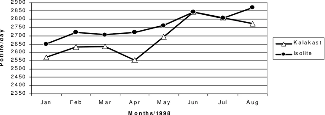
observation it was found that substitution of Kalakast by Isolite Concrete increased the average pot life (Figure 3). Normally the electrical resistance of the cathode increases with time and the lining is rebuilt after 1200 to 3000 days’ operation. One of the main causes suggested for the cathode failure is the penetration of sodium metal in the lining with the formation of C60Na and C68Na intercalation com-pounds20 between the graphite layer, causing swelling and
disruption21. The TiB2 composite cathode coating proposed
in the previous paragraph may result in improved cathode life, as it has been reported22 to be sodium resistant and
aluminum wettable.
The anode
The consumable carbon anode currently used has sev-eral disadvantages. It has an overvoltage of about 0.5 V and is an important source of impurities. The uneven consumption of the electrode creates disturbance in
interpolar distance. A major part of aluminum reduction cost (about 20%) is contributed by carbon anodes2b.
These problems have stimulated extensive investigations. Several formulations of aggregate coke, binder pitch and the paste material for anodes has been reported10.The
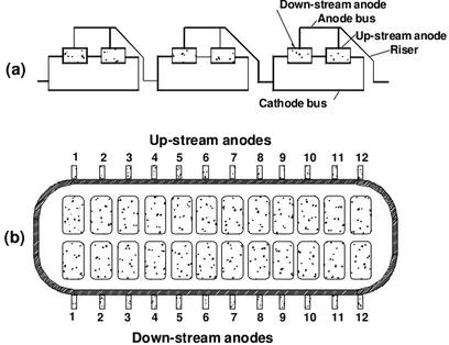
optimization of space utilization in the pot by changing the dimensions of the anodes and their relative position may have a significant improvement in economics of the smelter. In our observation plant each cell had two rows of 12 each of prebaked carbon anodes as shown in Figure 4. On analyzing the number of burnoffs during a period of six months it was noted that the anodes located on down-stream and on the pot-ends had more burnoff in comparison to the up-stream ones (Figure 5). Raising the level of these anodes by 4 cm resulted in decreasing the number of burnoffs. The down-stream curve (Figure 5) demonstrates that the anodes located on the ends (1, 12 and to a lesser extent 2, 11) and in the central part (6 and to a lesser extent 5, 7) of the cell were more exposed to
1 2 3 4 5 6 7 8 9 10 11 12
Up-stream anodes
(a)
(b)
Down-stream anode Anode bus
Up-stream anode Riser
Cathode bus
10 9 8 7 6 5 4 3 2
1 11 12
Down-stream anodes
0 50 100 150 200 250
1 2 3 4 5 6 7 8 9 10 11 12
P o sitio n o f a n o d e s
Fa
il
ur
e
s
U p-s trea m D ow n-s tr eam
Figure 5. Distribution of anode failures according to their relative position on up-stream and down-stream during the 1st semester of 1998.
the burnoff condition. This may be attributed to the strong magnetohydrodynamic phenomenon in cells function-ing at a very high amperage and with such bus bar design and anode riser configuration23. The complex metal
cir-culation pattern and a combination of a swirling and gy-ratory motion superimposed by metal pad surface waves may lead to short-circuiting and burnoffs. The proposed metal drained cells will be free from such problem.
Conclusion
The results of the study show that the energy consump-tion of the electrolyser is very high. Development of an inert anode and a stable cathode lining and control of the metal pad turbulence are vital for the cost reduction of the aluminum process. Horizontal currents interacting with the vertical component of the magnetic field are a signifi-cant cause of metal pad turbulence. Aluminum-wetted cath-ode blocks have no place for sludge to form under the metal pad and thereby cause horizontal electric current flow in the metal pad. By eliminating this source of insta-bility, current efficiency should be improved.
If the cathode is redesigned to be an aluminum-wetted and drained cathode, as described earlier, the ultimate alu-minum-bath interface stability will result. There will be no aluminum-to-anode shorting. This should provide the maxi-mum current efficiency for a given bath composition, cur-rent density and temperature. The stable aluminum inter-face should also allow a reduction of the anode-to-cathode distance producing a lower cell voltage. The higher current efficiency and lower cell voltage will improve the power efficiency.
Acknowledgements
The author is indebted to UFPB-CCT-PRODENGE and ALUMAR for providing facilities for this work and to the operation engineers for useful discussions.
References
1. Grjotheim, K.; Krohn, C.; Malinovsky, M.; Matia-sovsky, K.; Thonstad, J. Aluminium Electrolysis – Fundamentals
of Hall-Heroult Process; Alumi-nium-Verlag, Dusseldorf, 2nd Edition, 1982, p. (a) 6, (b) 394.
2. Grjotheim, K.; Welch, B.J. Aluminium Smelter Technology; Aluminium-Verlag, Dusseldorf, 2nd
Edition, 1988, p. (a) 5, (b) 158, (c) 161, (d) 254. 3. (a) Prasad, S. Trat. Superficie 1998, 87, 32; (b) Prasad,
S. 1996, 76, 18; (c) Prasad, S. 1993, 58, 23. 4. Prasad, S. Braz. J. Chem. Eng.2000 (in press). 5. Prasad, S.; Oliveira, L.G. J. Indian Chem. Soc. 1997,
71, 556.
6 . Solli, P.A.; Haarberg, T.; Eggen, T.; Skybakmoen, E.; Sterten, A. Light Metals; Warrendale , PA,
1994, 195.
7. Thonstad, J.; Rolseth, S. Electrochim. Acta 1976,
23, 223.
8. Sterten, A. Light Metals1991, 445.
9. Tarcy, G. P.; Rolseth, S.; Thonstad, J. Light Metals
1993, 227.
10. (a) Liu, Y.; Xiao, H. Proc. Intl. Symp. Molten Salts, Honolulu, 1987,744 ;(b) Liu, Y.; Xiao, H., Chen. Z.
Light Metals1989, 275; (c) Liu, Y.; Xiao, H/; Chen, Z. Light Metals 1993, 599; 1995, 247.
11. Forberg, H.O. Light Metals1996, 313.
12. Sekhar, J.A.; Nora, V.; Liu, J. Met. Trans. B, 1998,
29B, 59.
13. Zhang, H.; Nora, V.; Sekhar, J.A. Materials Used in the Hall Heroult Cell for Aluminum Production;
TMS; Warrendale, PA, 1994. 14. Haupin, W.E. J. Metals 1994, 28.
16. Silva, A.F. An. V Simp. Tec. Ind. Alumínio, São Paulo,
1995, 265.
17. Haverkamp, R.G.; Welch, B.J.; Metson, J.B. Light Metals 1994, 365.
18. Kvande, H.; Moxnes, B.P.; Skaar, J.; Solli, P.A. Light Metals 1997, 403.
19. Issaeva, L.A.; Poliakov, P.V.; Blinov, V.A.; Mikhalev, I.G.; Buzunov, V.I. Light Metals 1998, 507.
20. Asher, R.C. J. Nucl. Inorg. Chem. 1959, 10, 238. 21. Brilliot, P.; Lossius, L. P.; Oye, H.A. Aluminium1981,
5, 1746.
22. Sekhar, J.A.; Bello, V.N.; Liu, J.; Duruz, J.J. Light Metals1995, 507.
23. Oye, H.A.; Welch, B.J. Journal of Metals, 1998, 18.