A lumped parameter model of free expanding Plasma Focus
J. Gonz´alez∗
CNEA-CONICET and Instituto Balseiro, 8402 Bariloche, Argentina
M. Barbaglia, F. Casanova, and A. Clausse
CNEA-CONICET and Universidad Nacional del Centro, 7000 Tandil, Argentina (Received on 8 February, 2008)
In this paper, a model of Plasma Focus without surrounding cathode containing the radial expansion of the current sheath is presented. This configuration has been increasingly used in recent miniature devices. The model, based on the snowplow approximation, was applied to calculate the voltage along the pinch in a small 300 J device, showing good agreement with the experiments. The results can be useful in the design of x-rays applications of Plasma-Focus devices.
Keywords: Plasma Focus, pinch plasma, open-cathode, modeling
Introduction
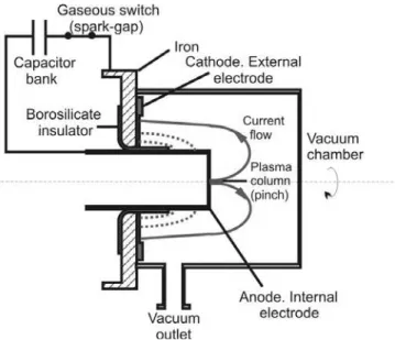
A Plasma Focus in a low pressure gas environment pro-duces a hot (around 0.3-1 keV) and dense (around 1025m−3) transient plasma for some nanoseconds, inducing ionization by means of a high pulsed voltage between a pair of coax-ial cylindrical electrodes. The hot plasma is the result of the time evolution of the electrical discharge that travels along the coaxial electrodes. The discharge starts over the insulator separating the electrodes, and then the plasma sheath take-off axially accelerated by the magnetic field generated by the current itself. After the current sheath runs over the open end of the central electrode, the plasma becomes rapidly com-pressed into a small column resulting in very hot and dense plasma (pinch).
Recently, small Plasma-Focus devices were developed aiming to applications of the pulsed radiation emissions of the pinch (Soto et. al. 2001, Silva et. al. 2002, Moreno et. al 2003, Silva et. al. 2003, Soto et. al. 2008, Rout et. al. 2009). Miniature devices were constructed following a spe-cial configuration derived from capillary discharges, where the surrounding cathode is replaced by a circular plate lo-cated at the base of the gun (Soto et. al. 2009, Barbaglia et. al 2009). This feature allows the current sheath to expand freely during the run down. Often, these devices are designed following empirical practices based on accepted scale laws (Lee and Serban 1996, Soto et. al. 2009).
Several simple models were offered in the past to assist the design of Plasma-Focus devices. Mathuthu et. al. (1997) proposed a semiempirical model in which the sheath has both radial and axial variation during the rundown phase, and both the damped current and pinch length are allowed to vary with time. Moreno et. al. (2000) derived a purely algebraic model capable of explaining the relation of the neutron production with the gas-filling pressure and the geometrical parameters of the device, based in the thermonuclear component of the fusion reaction.
More sophisticated theories were applied to describe in detail the kinematics of the current sheath. Moreno et. al. (2003) and Casanova et. al. (2005) presented a finite-element
∗Electronic address:[email protected]
approximation of Plasma Focus discharges, which repro-duced with very precisely the shape evolution of the sheath and the thermodynamics of the shock wave. Stepniewski (2004) proposed a numerical code based on the free points method to solve a set of non-ideal MHD equations including the kinetics of ionization.
Lumped parameters models were applied with excellent results, providing fast tools to assess the dynamic features of Plasma Foci operation. Lee (1989) and Lee et al. (2009) pro-posed a model based in the snow-plow approximation of the MHD equations, which was further extended to the simula-tion of different types of devices. Siahpoush et. al. (2005) and Goudarzi et. al (2008) adapted Lee’s model to the Fil-ippov type plasma focus geometry. Gonzalez et. al. (2004) presented a lumped parameter model of Mather-type Plasma Focus based on plane pistons, which explained the experi-mental neutron production of numerous devices assuming a thermonuclear reaction mechanism in the pinch.
In order to predict x-rays and the beam-target component of neutron emissions, more complex models taking into ac-count the generation of beams of electrons and ions should be developed. An important variable involved in the beam gen-erations of charged particles is the voltage acting along the pinch, which can exceed several times the charging voltage due to the inductance variation during the final compression. In the present article, an extension of Gonzalez et. al. (2004) lumped parameter model is presented, introducing the initial radial expansion of the current sheath. This fea-ture is important in the modeling of Plasma Focus without surrounding cathode, which is an increasingly used configu-ration in miniature devices (Soto et. al. 2009, Barbaglia et. al 2009). The model is applied to calculate the voltage along the pinch in a small 300 J device, showing good agreement against the experiments.
Description of the model
1989), the discharge process is partitioned in three stages, run-down, run-over, and pinch compression, and the evolu-tion of the current sheath is idealized by means of axial and radial shock-waves (Fig. 2).
In the run-down stage, the current sheet is represented by an annular piston moving forward in the axial direction and a planar cylinder moving outwards from the insulator. The length of the latter is variable and it is determined by the po-sition of the axial piston (Fig. 2). The mass and momentum equations of the axial plasma piston are:
dMx
dt =ξxρoπ
R2−R2a
vx (1)
d(Mxvx)
dt =
1 2lI
2 (2)
where a parameterξxis introduced to account for shape ef-fects, νx is the axial piston velocity, ρ0 the density of the stagnant gas ahead of the piston,Rthe position of the plasma cylinder moving outwards in the radial direction, andlis the linear inductance of the expanding current sheath:
l=µ0 2πln
R Ra
(3)
The radial expansion is modeled by a planar cylinder whose length is determined by the axial piston (Fig. 2). The mass and momentum balances of the radial expansion are:
dMR
dt =ξRρo2πR x vR (4)
d(MRvR)
dt =
µoI2
4π
x
R (5)
Note that the logarithmic factor of Eq. (3) does not appear in Eq. (5), since the magnetic pressure is constant over the radial piston area. In Eq. (4), the parameterξRis introduced to account for shape effects.
Assuming that the electric current flows at the backside of the sheet, the circuit equation is:
d dt
[Le+lX]
dQ dt
+Q
C =Vsg (6)
whereX is the position of the piston backside,Leis the
in-ductance of the external circuit, QandCare the capacitor charge and capacity, andVsgis the voltage drop on the spark
gap that is modeled as (Bruzzone et. al. 1989):
VS(t) =
Q0
C
[1+exp(−αto)]
1+exp[α(t−to)]
(7)
whereαandt0are constant parameters characteristic of the switch, andQ0the initial capacitor charge.
The run-over stage occurs after the sheath arrival at the anode’s open end, where the magnetic field accelerates the plasma toward the axis. The radial collapse is modeled by a radially imploding cylinder whose length is the difference between the axial piston and the anode length (Fig. 2). The mass and momentum balances and the electrical circuit
equation of the radial contraction are analogous to the corre-sponding radial expansion during the breakdown.
The thickness of the axial piston, δX, can be calculated regarding that the mass fraction trapped in the axial portion of the sheath is:
MX=ρcsvX=ρcsπ(R2ext−R2int)δX (8)
In Eq. (8),Rext andRintare the corresponding internal and
external radii of the sheath, and the current sheath densityρcs
is calculated assuming the Rankine-Hugoniot relation (An-derson 2006):
ρcs ρo
= (γ+1) (γ−1) +M22
(9)
whereMis the Mach number.
Similarly the thickness of the imploding piston,δR, is re-lated to its mass by:
MR=ρcsvR=ρcsπ
R2−(R−δR)2
(x+δx−z) (10)
Pinch model
The pinch compression starts when the front of the im-ploding cylinder reaches the axis (i.e., R−δR =0). The
resulting cylinder can be treated as a small plasma column compressed by the Lorentz force, which adiabatically in-creases its internal pressure and temperature until a mini-mum radius is reached (Fig. 3). Representing the pinch as a rigid cylinder should be interpreted as an effective model of a train of micropinches caused bym=0 instabilities, which is what experimental observations suggest. The momentum balance inside the pinch cylinder is written as (Gonzalez et. al. 2004):
d dt(ρpvrR
2
p) =Rp[pi−pM] (11)
whereρpis the pinch mass density,Rpandνrare the pinch
radius and its temporal derivative, pM is the magnetic
pres-sure:
pM=
µoI2
8π2R2 (12)
and pi the internal pinch pressure, which can be related to
the pinch radius (Gonzalez et. al. 2004).
The instantaneous voltage drop along the pinch is pro-duced by the inductance variation during the compression of the plasma column. Knowing the voltage drop between electrodes,Ve, the current and the inductance of the current
sheath,Lcs, the pinch voltage is calculated as:
Vp=Ve−d(Le+Lcs)I
FIG. 1: Diagram of an open-cathode Plasma Focus.
FIG. 2: Lumped parameter model of an open-cathode Plasma Focus (1. Breakdown and run-down, 2. Run-over, 3. Pinch).
FIG. 3: Diagram of the pinch model.
1.005 1.006 1.007 1.008
-0.4 -0.2 0.0
102 103 104 105
v R
(m/
P
s)
t (Ps)
V p
(V)
FIG. 4: Numerical evolution of the velocity of the pinch and voltage-drop along the pinch.
15
20
25
30
0
10
20
30
z =30 mmz=28 mm
z=23 mm
Vp (kV)
Charging voltage (kV)
FIG. 5: Peak voltage along the pinch measured and calculated for different charging voltages and different anode lengths.
Results
In order to validate the model, the numerical results were compared with experimental measurements in a Plasma Fo-cus with open cathode. Table I details the geometric and electrical parameters of the device (Barbaglia et. al. 2009). Systematic measurements of the pinch voltage dependence with the charging voltage were reported, including a study of the influence of the anode length, z. The experimental pinch voltage was obtained indirectly by processing the sig-nals of current and interelectrode voltage, combined with es-timations of the gun inductance.
The equations were solved using the FORTRAN LSODE subroutine package (Hindmarsh 1983). Fig. 4 shows the pinch evolution calculated for a 25 kV discharge over a 28 mm anode, where the velocity of the pinch radius, vR, and
10-2 10-1 100 101 100
101 102 103
z = 30 mm
z = 28 mm
z = 23 mm
V
p(kV)
p
o
(mbar)
FIG. 6: Charging-pressure dependence of the peak voltage along the pinch calculated for different anode lengths.
0 2 4 6 8 10
0 20 40 60 80
I
(kA)
p
o
[mbar]
z = 30
z = 28
z = 23
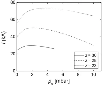
FIG. 7: Charging-pressure dependence of the pinch current calcu-lated for different anode lengths.
Fig. 5 shows the peak voltage along the pinch as function of the charging voltage, for each of the anode length used in the reference experiment. In spite of the dispersion of the data, it can be seen that the model follows quite well the trend using a single set of shape parameters,ξX=0.5 and
ξX=0.6, which was sufficient to explain the data measured
on three different anode lengths.
The sensitivity of the results to variations of the shape pa-rametersξXandξRwas studied for the reference case (z= 28 mm,V0=25kV), resulting:
ξX
Vp
dVp
dξX =0.075
ξR
Vp
dVp
dξR =−0.048
2 4 6 8 10 12
0 30 60 90 120
1.8 mbar 1 mbar
0.5 mbar
V
p(kV)
Anode length [cm]
0.1 mbar
FIG. 8: Peak pinch voltage as function of the anode length.
0.0 0.4 0.8 1.2 1.6 2.0
0 30 60 90 120
0 2 4 6 8 10
V
max p
(kV)
p(mbar)
z op
t
(cm)
FIG. 9: Optimum pinch voltage and the corresponding optimum anode length.
TABLE I
PARAMETERS OF THE EXPERIMENT AND THE MODEL
Symbol Parameter Value
C Bank capacity 0.8PF
V Charging voltage 18-28 kV
Le External inductance 65 nHy
z Anode length 2.3 to 3 cm
Ra Anode radius 0.31 cm
po Filling pressure 1.8 mbar
D Characteristic frequency of the spark gap 350 ns-1 to Characteristic delay of the spark gap 400 ns
[x Axial shape parameter 0.5
[R Radial shape parameter 0.6
which indicates that the model is robust respect to uncertain-ties of the shape parameters.
always decreases with the charging pressure.
Fig. 8 shows the variation of the pinch voltage with the an-ode length, keeping constant the charging pressure. It can be seen that there is an optimum anode length for each pressure, which maximizes the pinch voltage. Finally, Fig. 9 shows the maximum voltage and the corresponding optimum anode length as function of the charging pressure. Both magnitudes decrease as the pressure increases. These results can be use-ful in the design of Plasma Focus devices for applications of the x-ray emissions, which are known to be associated with the acceleration of electrons in the pinch.
Conclusions
A model of an open-cathode Plasma-Focus device was presented. The calculations of the pinch voltage have been
tested with available data at different charging voltages and anode lengths, showing good agreement. It should be noted that the numerical pinch duration should be interpreted as an effective value, since the present model represents the pinch as a single rigid cylinder, whereas experimental observations suggest the occurrence of a train of micropinches caused by m=0 instabilities (Liberman et. al. 1999). A two dimen-sional model capable to describe the axial structure of the pinch would be required for a systematic description of these effects.
The model set out here offers a useful tool to calculate and design of open-cathode Plasma-Focus devices applied to production of pulsed beams of charged particles.
[1] Anderson J. D., Hypersonic and high-temperature gas dynam-ics, AIAA, Virginia, 2nd Ed., p. 38, 2006.
[2] Barbaglia M., Bruzzone H., Acu˜na H., Soto L., Clausse A., Experimental study of the hard x-ray emissions in a Plasma Focus of hundreds of joules, Plasma Phys Contr. Fusion,51, 045001 (9pp), 2009.
[3] Bruzzone H, Kelly H and Moreno C, On the effect of finite closure time of switches in electrical circuits with fast transient behavior, Am. J. Phys.57,63, 1989.
[4] Casanova F., Moreno C., Clausse A. , Finite-elements numeri-cal model of the current-sheet movement and shaping in coax-ial discharges, Plasma Phys. Control. Fusion,47, 1239-1250, 2005.
[5] Di Lorenzo F., Lazarte A., Vieytes R., Clausse A., Moreno C., Anales de la Asociacin de Fsica Argentina (in spanish),16, 138-141, 2004.
[6] Gonzalez J., Florido P., Bruzzone H., Clausse A., A lumped parameter model of plasma focus, IEEE Transactions on Plasma Science,32, 1383-1391, 2004.
[7] Goudarzi S., Amrollahi R., Moghaddam R. S., A Model Based on Lumped Parameters for Filippov-type Plasma Focus De-vices, J Fusion Energ27, 195–199, 2008.
[8] Hindmarsh A., Odepack, a Systematized Collection of ODE Solvers, Scientific Committing ( R. S. Stepleman et al. Eds.), Amsterdam, p. 64, 1983.
[9] Lee S., “Technology of a small PF”, Proceedings of the Spring College on Plasma Physics, ICTP, Trieste, pp. 113–169 (1989).
[10] Lee. S., Serban A., “Dimensions and Lifetime of the Plasma Focus Pinch”, IEEE Trans. Plasma Sci.,24, 1101-1105, 1996. [11] Lee S., Saw S., Soto L., Springham V., Moo S., “Numerical experiments on plasma focus neutron yield versus pressure compared with laboratory experiments”, Plasma Phys. Con-trol. Fusion51, 075006 (11pp), 2009.
[13] Liberman M., De Groot J., Toor A., Spielman R., Physics of High-Density Z-Pinch Plasmas, Springer Verlag, New York, p. 127, 1999.
[13] Mathuthu M., Zengeni T., Gholap A., The Three-Phase The-ory for Plasma Focus Devices, IEEE Trans. Plasma Sci.25, 1382-1388, 1997.
[14] Moreno C., Bruzzone H., Martnez J., Clausse A., Conceptual Engineering of Plasma Focus Thermonuclear Pulsors, IEEE Trans. On Plasma Science,28, 1735-1741, 2000.
[15] Moreno C., Casanova F., Correa G., Clausse A., Experimental study and modeling of the plasma dynamics of magnetically driven shock waves in a coaxial tube, Plasma Phys. Control. Fusion,45, 1989-1999, 2003.
[16] Rout R., Mishra P., Rawool A., Kulkarni L., Gupta S., Bat-tery powered tabletop pulsed neutron source based on a sealed miniature plasma focus device, J. Phys. D: Appl. Phys. 41, 205211 (5pp), 2008.
[17] Shapiro A., The Dynamics and Thermodynamics of Com-pressible Fluid Flow, The Ronald Press Company, I, 112, 1953.
[18] Siahpoush V., Tafreshi M., Sobhanian S., Khorram S., Adap-tation of Sing Lee’s model to the Filippov type plasma focus geometry, Plasma Phys. Control. Fusion47,1065–1075, 2005. [19] Silva P., Soto L., Moreno J., Sylvester G., Zambra M., Al-tamirano L., Bruzzone H., Clausse A., Moreno C., A Plasma Focus Driven by a Capacitor Bank of Tens of Joules, Rev. Sci. Instruments73, 2583, 2002.
[20] Silva P., Moreno J., Soto L., Birstein L., Mayer R., Kies W., Neutron Emission from a Fast Plasma Focus of 400 Joules”, Applied Physics Letters83, 3269, 2003.
[21] Soto L., Esaulov A., Moreno J., Silva P., Sylvester G., Zambra M., Nazarenko A., Clausse A., Transient Electrical Discharge in Small Devices, Phys. Plasma8, 2572, 2001.
[22] Soto L., Silva P., Moreno J., Zambra M., Kies W., Mayer R., Clausse A., Altamirano L., Pavez C., Huerta L., Demonstra-tion of neutron producDemonstra-tion in a table-top pinch plasma focus device operating at only tens of joules, J. Phys. D: Appl. Phys. 41,205215 (7pp), 2008.
[23] Soto L., Pavez C., Moreno J., Barbaglia M., Clausse A., Nanofocus: an ultra-miniature pinch focus device with sub-millimetric anode operating at 0.1 J, Plasma Sources Sci. Techn.18,015007 (5pp), 2009.