Advances in Mechanical Engineering 2015, Vol. 7(5) 1–10
ÓThe Author(s) 2015 DOI: 10.1177/1687814015585427 aime.sagepub.com
Influence of pick working angle
on cutting performance of auger
miner’s aiguille
Lin Fu
1, Changlong Du
1, Jianping Li
1and Kehong Zheng
2Abstract
To study the influence of pick working angles on cutting performance of auger miner’s aiguille, aiguilles with different pick working angles were developed and their performance were tested on coal cutting test-bed. Cutting performance eva-luation system of the aiguille was established first, and then evaeva-luation indexes such as average load, load fluctuation coef-ficient, and specific energy were analyzed by statistical method. The research indicates that the torque and specific energy of the aiguille decrease first and then increase with increased pick working angles. The feed resistance decreases with the increase in two working angles. The energy consumed by the feed resistance is very small relative to the total energy and can be ignored. When the cutting angle is between 45°and 50°and the tilt angle is about 20°, the torque
and specific energy of the aiguille will be at a minimum and the load stability of the aiguille will also be ideal.
Keywords
Auger miner, aiguille, pick working angle, cutting performance
Date received: 19 October 2014; accepted: 5 March 2015
Academic Editor: Hiroshi Noguchi
Introduction
Auger miner is a kind of mining equipment which is usually used in thin seam, whose structure and working principle are introduced in other articles.1,2 Aiguille is the cutting mechanism of the auger miner, and its cut-ting performance will directly affect the stability, relia-bility, and economics of the machine. The cutting performance of the aiguille is influenced by many fac-tors such as pick working angles, pick arrangement, and motion parameters.3As one of all factors, the pick working angle has a significant impact on the cutting performance of the aiguille, whose value will directly affect pick cutting and aiguille wear.
A lot of work has been done on pick working angles. Nishimatsu4 and Gao et al.5 studied the cutting force of the point-attack pick in theory and gave the relation-ship between the cutting force and pick working angles. Khair and colleagues6,7 chose four different angles of
15°, 30°, 45°, and 60°to study attack angles of picks on
the continuous miner. They found that the most ideal condition for force transmission by the pick to the coal will be a 30°–45° attack angle. Larger force will be
required for the pick to penetrate the coal if the attack angle is too small or too large. Kim et al.8,9conducted full-scale rotary cutting tests using a test drum. They studied the influence of attack angles and skew angles to pick rotation. Liu et al.10and Du et al.11studied the pick installing angles and obtained the relationships
1College of Mechanical and Electrical Engineering, China University of
Mining and Technology, Xuzhou, China
2College of Mines and Earth Sciences, University of Utah, Salt Lake City,
UT, USA
Corresponding author:
Changlong Du, College of Mechanical and Electrical Engineering, China University of Mining and Technology, Xuzhou 221116, China. Email: [email protected]
between impact angle, inclination angle, and skew angle. They pointed out that the cutting force will be smallest when the direction of the resultant force of pick follows its axis, and the relationship derived among the installing angles should be satisfied. Goktan and Gunes12 set up a semi-empirical mathematical model of peak cutting force for a single pick. The model gives the functional relationship between peak cutting force and pick attack angle. Liu et al.13studied the influence of the attack angle on the pick cutting force and found that the cutting force will be smallest only when the attack angle is chosen near some critical value. Hekimoglu and Fowell14,15 and Hekimoglu16 studied the vibration of the cutting head. Their research indicates that the harmful vibration can be removed by reasonable design of cutting head. The cutting head will own small specific energy when the tilt angle of nose pick is between 65°and 70°. Brian Asbury et al.17
dis-cussed the respirable dust generated by continuous miners. The experimental results in their article showed that the attack angle of the pick has great influence on dust production.
Previous research on the pick working angle is mainly about single pick or about shearer drum, road-header cutting head, and continuous miner drum. The aiguille of the auger miner has some difference with other cutting mechanisms with point-attack picks in working conditions and structures, so previous research may not be suitable for the aiguille. It is necessary to study the pick working angle of the aiguille specifically. The article will develop test aiguilles with different pick working angles first and then test their cutting perfor-mance on a coal cutting test-bed. Finally, the influence of pick working angles on load and specific energy was studied. The research will provide the basis for the design of the aiguille.
Development of test aiguilles and coal
cutting test-bed
Test aiguilles
The test aiguille is shown in Figure 1, which mainly consists of point-attack picks, top disk, rib plates, tooth holders, helical blades, and mandrel.18 A total of 13 picks were installed on the aiguille along the three-dimensional spirals (Figure 1(a)). The same circumfer-ential and axial spacing were kept between adjacent picks on the same spiral. Only one pick was arranged at the same axial coordinates. The envelop surface of the aiguille is shown in Figure 1(b). It consists of a plane and a paraboloid. The tips of four picks on the top disk are located on the plane and one of the nine picks on rib plates on the paraboloid.
In general, working angles are used to determine the spatial orientation of the pick and make the pick cut coal more effectively. Two pick working angles are defined here to design test aiguilles. One is called cut-ting angle, and another is called tilt angle. They can be explained by Figure 2. In this figure, OF is the center line of a pick, and F stands for the pick’s head. OXYZ is a Cartesian coordinate, whose origin is located on line OF. The axisZis parallel to the aiguille center line, and the positive direction of the axis Y is consistent with the circular motion tangential of the pick. Cutting angle d refers to the acute angle between pick center line OF and circular motion tangential BF. Tilt anglee
always refer to the working angle of the pick on the rib plate.
A total of seven test aiguilles were developed in this study. They have the same parameters except pick working angles. The aiguille numbers and the corre-sponding pick working angles are listed in Table 1.
Coal cutting test-bed
A coal cutting test-bed was built to test the cutting per-formance of aiguilles. The test-bed mainly consists of mechanical transmission system, control system, and measure system.
Mechanical transmission system. The mechanical transmis-sion system of the coal cutting test-bed is shown in Figure 3, which is composed of hydraulic cylinder, vari-able frequency motor, gearbox, and so on. The varivari-able frequency motor passes the power to the aiguille through gearbox, torque sensor, and bearing support and drives the aiguille rotating. Two spherical roller bearings and one thrust bearing are installed on the bearing support to bear radial and axial loads of the aiguille, respectively. The motor, reducer, torque sen-sor, and bearing support are all fixed on the mobile platform by bolts and can move forward and backward together with the mobile platform under the action of the hydraulic cylinder. Drilling process of the aiguille can be simulated by a combination of rotary and trans-lational motion. A coal wall is placed in front of the aiguille and can be cut by the aiguille.
Control and measurement system. The control system is mainly responsible for the motion control of the test-bed. Rotational speed of the aiguille is adjusted by con-trolling the motor with a frequency converter. Feed speed of the aiguille is controlled by a variable pump and hydraulic cylinder system.
The measurement system is responsible for signal measurement and date acquisition of the test-bed, whose structure is shown in Figure 4. In the system, sensors are responsible for measuring physical signals Figure 2. Working angles of the pick.
Table 1. Pick working angles of test aiguilles.
Aiguille number 1 2 3 4 5 6 7
Cutting angled 31° 39° 47° 55° 47° 47° 47°
Tilt anglee 30° 30° 30° 30° 10° 20° 40°
Figure 3. Mechanical transmission system of coal cutting test-bed.
1, load cell; 2, hydraulic cylinder; 3, slide guide; 4, mobile platform; 5, variable frequency motor; 6, gearbox; 7, torque sensor; 8, bearing support; 9, aiguille; 10, coal wall.
such as speed and force and transforming them into electrical signals. The data acquisition card (DAQ) con-verts electrical signals into digital signals which can be recognized, dealt, and stored by the industrial personal computer (IPC). The IPC provides a platform for the data manipulation such as operation, storage, and dis-play. LabVIEW is used to compile the data acquisition program. LabVIEW is a data flow programming
lan-guage developed by National Instruments (NI).
Applications developed for this work are programmed in LabVIEW 2013 version. A total of three sensors were used on the test-bed. The load cell was used to measure the aiguille’s feed resistance. The torque sensor was used to measure the torque and rotational speed of the aiguille and the displacement sensor to measure the feed speed.
Cutting performance evaluation system of
the aiguille
Evaluation system must be built first to evaluate the cutting performance of the aiguille. For the coal cutting mechanism, loads, energy consumption, and lump coal ratio are the most important aspects for cutting perfor-mance.19,20 Combined with the working condition of the auger miner, several cutting performance evalua-tion indexes were defined here from two aspects of the load and energy consumption.
The aiguille mainly bears two loads, of which one is the torque around the axis and another is the feed resis-tance along the feed direction. Because of structural symmetry, other loads of the aiguille are so small that they can be ignored. The average load, average peak load, and load fluctuation coefficient were introduced to evaluate the load condition of the aiguille. The aver-age load refers to the statistical averaver-age for a load. It reflects the average load condition of the aiguille and can be expressed as
F= 1
ns
Pns
i=1 Fs
i
T= 1
ns
Pns
i=1 Ts i 8 > > < > > :
ð1Þ
where F is the average feed resistance of the aiguille, kN;Fs
i is the feed resistance at the ith sampling point, kN;T is the average torque of the aiguille, N m; Ts
i is the torque at theith sampling point, N m;nsis the total
number of sampling points.
The average peak load is the statistical average for more than one local maximums of a load. It reflects the maximum load state of the aiguille and can be defined as
Fp= 1 np
X
np
j=1 Fpsj
Tp= 1 np
X
np
j=1 Tjps 8 > > > > < > > > > :
ð2Þ
where Fp is the average peak feed resistance of the
aiguille, kN; Fjps is the jth local maximum of the feed resistance, kN; Tp is the average peak torque of the
aiguille, N m;Tips is thejth local maximum of the tor-que, N m;npis the total number of local maximums.
The load fluctuation coefficient is defined to measure the load stability of the aiguille. Considering the differ-ence of average loads between aiguilles, the load fluc-tuation coefficient is defined as
jF=
ffiffiffiffiffiffiffiffiffiffiffiffiffiffiffiffiffiffiffiffiffiffiffiffiffiffiffiffiffiffiffi 1
ns
Pns
i=1
(Fs
i F)
2 s
=F
jT=
ffiffiffiffiffiffiffiffiffiffiffiffiffiffiffiffiffiffiffiffiffiffiffiffiffiffiffiffiffiffiffi 1
ns
Pns
i=1
(Ts
i T)
2 s =T 8 > > > > < > > > > :
ð3Þ
wherejF is the fluctuation coefficient of the feed
resis-tance; jT is the fluctuation coefficient of the torque.
The smaller the load fluctuation coefficient, the more stable the load is.
The specific energy is one of the most important fac-tors in determining the efficiency of cutting systems and defined as the work to excavate a unit volume of coal.19 For the aiguille, the specific energy mainly consists of two parts. One part is the energy caused by the torque, and another part is the energy caused by the feed resis-tance. So, the specific energy can be described as
HW=HWT+HWF=(
T n+1000Fv )tc 3:63106
Vc ð4Þ
where HW is the specific energy of the aiguille, kW h/ m3;HWT is the specific energy caused by the torque, kW h/m3;HWF is the specific energy caused by the feed resis-tance;nis the rotational speed of the aiguille, rad/s;vis the feed speed of the aiguille, m/s;tcis the cutting time; Vcis the volume of coal cut by the aiguille during time tc, m3.
Because of low feed speed for the aiguille, coal on the inner surface of the coal hole is cut completely. So, the volume of cut coalVccan be expressed as
Vc=pR2holevtc ð5Þ
whereRholeis the radius of the coal hole, m. According to equations (4) and (5), there is
HW= (
T n+ 1000Fv )
3:63106 pR2
holev
The ratio of the specific energy is also important for the design of the aiguille. It determines that the focus should be considered when we design. According to equation (4), the ratio of specific energy caused by the feed resistance can be expressed as
hF=H
F W
HW =
1000Fv
T n+1000Fv 3
100% ð7Þ
Aiguille test and results’ discussion
Seven drilling experiments were done to test the cutting performance of aiguilles. The same test conditions always were kept for any experiment. That is the same motion parameters and the same coal wall performance parameters. The rotational speed and feed speed of the aiguille are 60 r/min and 0.55 m/min, respectively. All coal walls are made up of coal ash, cement, and water by 6:1:1.5.
The torque and feed resistance of every aiguille were collected in real time during test. Figure 5 shows typical load curves of the aiguille drilling. Three stages of the aiguille drilling process can be seen by the figure. In the first stage, the aiguille has no contact with the coal wall, and all loads fluctuate around 0. In the second stage, picks on the aiguille drill into the coal wall one by one, and loads of the aiguille increase gradually. In the last stage, the aiguille has completely drilled into the coal wall, and all loads have not increased again and tend to be stable. The study only pays attention to the last stage, and load data for 10 s at this stage were analyzed statistically.
Effect of cutting angle on cutting performance
No. 1–no. 4 aiguilles are used to test the effect of pick cutting angle on the cutting performance of the aiguille. Cutting performance statistics of different cutting angles are shown in Table 2. According to Table 2, we
can map the trend curve of each evaluation index with the cutting angle.
The relationship between torque and cutting angle is shown in Figure 6. As shown in the figure, with the increase in cutting angle, both average torque and aver-age peak torque will decrease first to a certain level, and then increase gradually. The cutting angle of 45°–
Figure 5. Load curves of the aiguille drilling: (a) cutting torque and (b) feed resistance.
Table 2. Cutting performance statistics of different cutting angles.
d(°) T(N m) Tp(N m) j
T F(kN)
31 1392.91 1533.93 0.056 10.54
39 1273.84 1441.08 0.067 8.93
47 1009.57 1113.81 0.058 8.77
55 1053.08 1226.79 0.058 8.17
d(°) Fp(kN) j
F HW(kW h/m3) hF(%)
31 12.17 0.074 1.22 1.1
39 10.55 0.093 1.11 1.0
47 10.01 0.084 0.88 1.3
50°can offer the smallest torque for the aiguille. In
the-ory, the coal failure mode will transform gradually from the tensile and shear failure into the compression failure with increasing cutting angle,21,22 which means more cutting force will be asked for the pick to break the coal. In other words, the increasing cutting angle will always increase the torque of the aiguille. The main reason for difference between experiment results and the theory is as follows. When the cutting angle is too small, the tooth holder and the pick body will contact with the coal and serious friction will happen. In this condition, more torque will be needed for the aiguille to overcome the friction effect. As the cutting angle increases to a certain level, interference between the tooth holder and the coal gradually disappears and the torque of the aiguille will reach to the minimum. Further increasing the cutting angle, although the tooth holder is still not in contact with the coal, the pick will damage the coal by compression. That will make the pick suffer from larger cutting force. It means the aiguille will suffer from larger torque.
The correctness of the above analysis can be verified by checking the wear condition of aiguilles, which is shown in Figure 7. We can see that tooth holders on no. 1 and no. 2 aiguilles suffered from serious wear because of the small pick cutting angle. In contrast, tooth holders on no. 3 and no. 4 aiguilles with larger pick cutting angles are not damaged and their struc-tures are very intact. Significant wear on some picks of no. 4 aiguilles can be seen, which means too large cut-ting angle indeed increases the pick’s cutcut-ting force.
The relationship between the feed resistance of the aiguille and the pick cutting angle is shown in Figure 8. The average feed resistance and average peak feed resis-tance have the same change rule with the cutting angle. Both of them decrease with the increase in the cutting angle. In fact, increasing the cutting angle can eliminate interference between the tooth holder and the coal to avoid the additional feed resistance caused by the
interference. In addition, a larger cutting angle can reduce the feed resistance on each pick by reducing the contact area between the pick and the coal in the feed direction of the auger.
By the above analysis, it is impossible to minimize the torque and feed resistance at the same time by changing the cutting angle, so the specific energy of the aiguille is further studied. Figure 9 shows the relation-ship between the specific energy and the cutting angle. Similar to the torque, the specific energy of the aiguille first decreases and then rises with the increase in the cutting angle. 45°–50°cutting angle provides lower
spe-cific energy for the aiguille. In fact, the energy con-sumption of the aiguille is mainly decided by the torque. Table 2 shows that the specific energy caused by the feed resistance is less than 1.5% of the total spe-cific energy. So, the influence of the feed resistance on the specific energy can be ignored.
Besides the load magnitude, the load fluctuation is also affected by the pick cutting angle. Figure 10 shows the relationship between load fluctuation coefficients and cutting angles. With the increase in the cutting angle, fluctuation coefficients of the torque and the feed resistance first increase to some level, and then decrease, finally keeping smooth. Although there is some differ-ence between the torque and the feed resistance with the cutting angle, the fluctuation condition of the two loads is in accordance. When the cutting angle is in 45°–50°,
although two fluctuation coefficients are not minimum, their values are still satisfactory.
Effect of tilt angle on cutting performance
No. 3, no. 5, no. 6, and no. 7 aiguilles are used to test the effect of pick tilt angle on the cutting performance of the aiguille. Cutting performance statistics of differ-ent tilt angles are shown in Table 3. According to Table 3, we can map the trend curve of each evaluation index with the tilt angle.
The relationship between the torque of the aiguille and the pick tilt angle is shown in Figure 11. This figure shows that average torque and average peak torque ini-tially decrease, but finally increase with the increasing tilt angle. The torque of the aiguille achieves the mini-mum when the tilt angle is near 20°. In fact, the tilt
avalanche freely, but one on side II cannot. More cut-ting force and energy will be required for the pick to break the coal, which means the aiguille will suffer from
larger torque. In addition, too large tilt angle may cause the harmful friction between tooth holders and the coal.
Figure 7. Wear condition of aiguilles with different cutting angles: (a) no. 1 aiguille, (b) no. 2 aiguille, (c) no. 3 aiguille, and (d) no. 4 aiguille.
Figure 8. Relationship between feed resistance and cutting
angle. Figure 9. Relationship between specific energy and cutting
The relationship between the feed resistance of the aiguille and the tilt angle is shown in Figure 13. As shown in this figure, both the average feed resistance and average peak feed resistance decrease with the increase in the tilt angle. As shown in Figure 12, forces on the opposite sides of the pick along the feed direction are unbalanced, and the force on side I is much larger than the force on side II. So, the feed resistance of the pick performs as a unidirectional load whose direction is in accordance with the feed velocityv. As the tilt angle increases, because the coal on side II cannot avalanche freely, the force of the pick on side II will become larger, so more force of the pick on side I is balanced. As a result, the total feed resistance of the aiguille becomes smaller with the increasing tilt angle. In fact, the role of the tilt angle along the feed direction is similar to the role of the cutting angle along the circumferential direction. When choosing the tilt angle, we must consider its influence on torque and feed resistance at the same time.
The relationship between the specific energy of the aiguille and the tilt angle is shown in Figure 14. It is
obvious that too small or too large tilt angle will increase the specific energy of the aiguille. Only when the tilt angle is chosen around 20°, the specific energy
of the aiguille is minimum. As mentioned above, the specific energy of the aiguille is mainly decided by the torque, so it has similar rule with the torque.
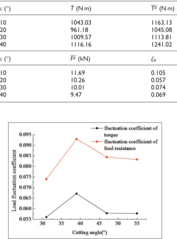
The load fluctuation with the tilt angle is shown in Figure 15. We can see that two load fluctuation coeffi-cients have the same change rule with the tilt angle. That means torsional vibration and feed vibration will interact with each other. With the increase of the tilt angle, two load fluctuation coefficients will decrease firstly, then increase and finally decrease slowly again. The tilt angle about 20° not only provides the
mini-mum specific energy for the aiguille but also provides the minimum load fluctuation coefficients.
Conclusion
Drilling experiments were carried out on a coal cutting test-bed to test the cutting performance of aiguilles with different working angles. Loads and energy consump-tion data of all aiguilles were acquired and analyzed in Table 3. Cutting performance statistics of different tilt angles.
e(°) T(N m) Tp(N m) jT F(kN)
10 1043.03 1163.13 0.064 9.9
20 961.18 1045.08 0.042 9.35
30 1009.57 1113.81 0.058 8.77
40 1116.16 1241.02 0.056 8.56
e(°) Fp(kN) jF HW(kW h/m3) hF(%)
10 11.69 0.105 0.91 1.4
20 10.26 0.057 0.84 1.4
30 10.01 0.074 0.84 1.3
40 9.47 0.069 0.97 1.1
Figure 10. Relationship between load fluctuation coefficient and cutting angle.
statistical methods, and some conclusions have been obtained as follows:
1. The pick cutting angle and tilt angle have a sim-ilar influence on the torque and specific energy
of the aiguille. With the increasing working angles, both torque and specific energy will decrease first and then increase. A 45°–50°
cut-ting angle and about 20°tilt angle can make the
aiguille have the minimum torque and specific energy.
2. With two pick working angles, the average load and average peak load have the synchronous change rule. In other words, they will increase or decrease synchronously.
3. The feed resistance of the aiguille decreases with the increase in the cutting angle and tilt angle. The specific energy generated by the feed resis-tance is far less than the one generated by the torque. When studying the energy consumption of the aiguille, the influence of feed resistance can be ignored.
4. Fluctuation coefficients of the torque and feed resistance are consistent with the change in pick working angles. When the torque and feed Figure 12. Cutting pattern of picks with different tilt angles: (a) free cutting and (b) semi-enclosed cutting.
Figure 13. Relationship between feed resistance and tilt angle.
Figure 14. Relationship between specific energy and tilt angle.
resistance are minimum, load fluctuations are also satisfactory.
Declaration of conflicting interests
The authors declare that there is no conflict of interests regarding the publication of this article.
Funding
The authors would like to acknowledge the Foundation of National 863 Plan of China (2012AA062102), the National Natural Science Foundation of China (51375478), and the Qing Lan Project.
References
1. Fu L, Du CL and Gao KD. Dynamical simulation model of auger miner’s working mechanism based on vir-tual prototyping technology.Adv Mater Res 2011; 338: 199–204.
2. Liu SY, Cui XX and Liu XH. Coupling vibration analy-sis of auger drilling system. J Vibroeng 2013; 15: 1442–1453.
3. Fu L, Du CL, Cui XX, et al. Simulation study on cutting performance of auger drill miner’s aiguille. Int J Earth Sci Eng2014; 7: 83–89.
4. Nishimatsu Y. The mechanics of the rock cutting.Int J Rock Mech Min1972; 9: 261–271.
5. Gao KD, Du CL, Jiang HX, et al. A theoretical model for predicting the peak cutting force of conical picks. Fratt Integr Strutt2014; 8: 43–52.
6. Khair AW. Research and innovations for continuous miner’s cutting head, for efficient cutting process of rock/coal. In:17th international mining congress and exhi-bition of Turkey, Ankara, Turkey, 19–22 June 2001, pp.45–55. Ankara: Kozan Ofset Matbaacilik San ve Tic Ltd Sti.
7. Khair AW, Reddy NP and Quinn MK. Mechanisms of coal fragmentation by a continuous miner.Min Sci Tech-nol1989; 8: 189–214.
8. Kim E, Rostami J, Swope C, et al. Study of conical bit rotation using full-scale rotary cutting experiments. J Min Sci2012; 48: 717–731.
9. Kim E, Rostami J and Swope C. Full scale linear cutting experiment to examine conical bit rotation. J Min Sci 2012; 48: 882–895.
10. Liu SY, Cui XX, Du CL, et al. Method to determine installing angle of conical point attack pick.J Cent South Univ Technol2011; 18: 220–226.
11. Du CL, Liu SY, Cui XX, et al. Study on pick arrange-ment of shearer drum based on load fluctuation.J China Univ Min Technol2008; 18: 305–310.
12. Goktan RM and Gunes N. A semi-empirical approach to cutting force prediction for point-attack picks.J South Afr Inst Min Metall2005; 105: 257–263.
13. Liu XH, Liu SY, Cui XX, et al. Interference model of conical pick in cutting process. J Vibroeng 2014; 16: 103–115.
14. Hekimoglu OZ and Fowell RJ. Practical aspects of rear pick arrangements on boom-type tunneling machine heads.Min Sci Technol1990; 10: 221–230.
15. Hekimoglu OZ and Fowell RJ. From research into prac-tice: in-situ studies for design of boom tunneling machine cutting heads. In:Proceedings of the 31st symposium on rock mechanics, Golden, CO, June 1990, pp.481–488. USA: A A Balkema Publishers.
16. Hekimoglu OZ. The radial line concept for cutting head pick lacing arrangements.Int J Rock Mech Min1995; 32: 301–311.
17. Asbury B, Dezeeuw M, Cigla M, et al. Results of practi-cal design modifications for respirable dust reduction on continuous miners in underground coal mining. In: Pro-ceedings of the annual meeting of the society for mining, metallurgy and exploration (SME), Cincinnati, OH, 24– 26 February 2003, pp.1–9.
18. Du CL, Liu SY, Cui XX, et al. Study on design of oper-ating mechanism of auger mining machine.Proced Earth Planet Sci2009; 1: 1406–1410.
19. Bilgin N, Demircin MA, Copur H, et al. Dominant rock properties affecting the performance of conical picks and the comparison of some experimental and theoretical results.Int J Rock Mech Min2006; 43: 139–156.
20. Balci C and Bilgin N. Correlative study of linear small and full-scale rock cutting tests to select mechanized exca-vation machines.Int J Rock Mech Min2007; 44: 468–476. 21. Goktan RM. Effect of cutter pick rake angle on the fail-ure pattern of high-strength rocks.Min Sci Technol1990; 11: 281–285.