Effects of Simulated Marker Placement
Deviations on Running Kinematics and
Evaluation of a Morphometric-Based
Placement Feedback Method
Sean T. Osis1,3*, Blayne A. Hettinga1,3, Shari Macdonald3, Reed Ferber1,2,3
1Faculty of Kinesiology, University of Calgary, Calgary, Canada,2Faculty of Nursing, University of Calgary, Calgary, Canada,3Running Injury Clinic, Calgary, Canada
Abstract
In order to provide effective test-retest and pooling of information from clinical gait analyses, it is critical to ensure that the data produced are as reliable as possible. Furthermore, it has been shown that anatomical marker placement is the largest source of inter-examiner vari-ance in gait analyses. However, the effects of specific, known deviations in marker place-ment on calculated kinematic variables are unclear, and there is currently no mechanism to provide location-based feedback regarding placement consistency. The current study addresses these disparities by: applying a simulation of marker placement deviations to a large (n = 411) database of runners; evaluating a recently published method of morphomet-ric-based deviation detection; and pilot-testing a system of location-based feedback for marker placements. Anatomical markers from a standing neutral trial were moved virtually by up to 30 mm to simulate deviations. Kinematic variables during running were then calcu-lated using the original, and altered static trials. Results indicate that transverse plane angles at the knee and ankle are most sensitive to deviations in marker placement (7.59 degrees of change for every 10 mm of marker error), followed by frontal plane knee angles (5.17 degrees for every 10 mm). Evaluation of the deviation detection method demonstrated accuracies of up to 82% in classifying placements as deviant. Finally, pilot testing of a new methodology for providing location-based feedback demonstrated reductions of up to 80% in the deviation of outcome kinematics.
Introduction
Anatomical marker placement has been identified as the single largest source of variance in repeated gait analyses using motion-capture techniques, resulting in inter-examiner differences of up to 34 degrees for certain joint angles [1]. This problem is particularly relevant for large, multi-site biomechanical gait studies where inter-tester differences can preclude pooling of data [2,3]. To address this problem, a novel method was developed which‘scores’marker placement by comparing marker data transformed by generalized-Procrustes analysis (GPA), to a large normative database [4].
OPEN ACCESS
Citation:Osis ST, Hettinga BA, Macdonald S, Ferber R (2016) Effects of Simulated Marker Placement Deviations on Running Kinematics and Evaluation of a Morphometric-Based Placement Feedback Method. PLoS ONE 11(1): e0147111. doi:10.1371/journal. pone.0147111
Editor:Alejandro Lucia, Universidad Europea de Madrid, SPAIN
Received:July 27, 2015
Accepted:December 29, 2015
Published:January 14, 2016
Copyright:© 2016 Osis et al. This is an open access article distributed under the terms of theCreative Commons Attribution License, which permits unrestricted use, distribution, and reproduction in any medium, provided the original author and source are credited.
Data Availability Statement:All relevant data are within the paper and its Supporting Information files.
Funding:This research was partially funded by a grant from Alberta Innovates: Health Solutions (grant # 200700478) and a Discovery Grant from the Natural Sciences and Engineering Research Council of Canada (grant # 1030390). Both received by RF.
The outcome from this analysis is known as an inter-quartile range ratio (IQRR), and is a standardized, non-parametric, statistical description of the location of a given marker ment. It has been shown that the IQRR is capable of indicating divergence in marker place-ments between a single Novice and Expert, and measureplace-ments over time can show how a single Novice alters their placements [4]. While these results provide valuable insights, there is a lack of contextual information about how downstream kinematic data may be affected by marker deviations described by the IQRR. Therefore, two questions arise: 1) which anatomical markers have the greatest influence over outcome kinematics, and 2) what is an‘acceptable’ value for the IQRR at each location to indicate that deviations in marker placement are within some acceptable limit.
A simulation approach has produced valuable descriptions of deviation effects for knee markers [5], and propagation into coordinate systems [6]. However, these studies did not com-prehensively address the impact of specific marker placement deviations on lower extremity kinematics of gait analysis, particularly in light of anatomical variance. By simulating devia-tions in marker placement, at multiple locadevia-tions, for a large subject cohort, it is possible to determine the worst-case effects of these deviations. Additionally, by considering the IQRR score as a binary classifier of deviation, conventions can be established for what constitutes ‘acceptable’or‘unacceptable’IQRR scores.
Therefore, the purposes of this study were to:
1. Use simulated deviations in marker placement to calculate resulting changes in downstream gait kinematics and quantify the relationships between marker placement deviations and changes in kinematic variables
2. Evaluate the classification performance of IQRR scores by considering kinematic changes in terms of Mathews’correlation coefficient (MCC), false positive rates (fall-out), and true pos-itive rates (sensitivity) for a range of kinematic and IQRR thresholds
3. Conduct a real-world pilot study of IQRR-based deviation detection with novice biomechanists.
Materials and Methods
Data Collection
A total ofn = 411subjects were included in this study (gender:215 females; age:40.0 ± 11.6 yrs; height:172.3 ± 8.9 cm; mass:71.2 ± 13.1 kg). All were patients who participated in clinical activ-ities at the Running Injury Clinic, and all gave written, informed consent for their data to be used for research purposes. Patients presented with a variety of common running injuries (i.e. patellofemoral pain syndrome, iliotibial band syndrome), however, none presented with condi-tions known to drastically influence lower body morphology (i.e. amputation, developmental disorders, lower extremity orthopaedic surgery, etc). Inclusion criteria were kept intentionally broad in order to represent a large segment of the population in a morphological sense, thereby improving the generalizability of the method. Ethical approval was given by the Conjoint Health Research Ethics Board to review and analyze patient data for the current study.
All marker placements were performed by one tester (the Expert) with 15 years of experience in clinical anatomy and more than 800 3D kinematic gait analyses performed.
In brief, the marker model used for the lower extremity consisted of the following conven-tions. Ankle joint centres were located at the midpoint of the lateral and medial malleoli mark-ers. Knee joint centres were located at the midpoint of markers placed over the lateral and medial joint lines. Hip joint centers were determined using trochanter markers and locating them at 25% of the inter-trochanteric distance [9].
A joint coordinate system [10] was used to construct segment-aligned coordinate systems, relative to segment tracking markers. Briefly, each segment coordinate system was created by aligning the long axis of the segment with the vector connecting adjacent joint centres. The anterior axis was then calculated from the cross product of the long axis and the vector con-necting medial and lateral markers of the distal joint. Finally, the hinge axis was calculated as the cross-product of the anterior and long axes. Segment tracking clusters were affixed to the pelvis, thighs, shanks and feet.
Each subject performed a standing neutral trial with all anatomical markers to establish the anatomical model, and their position was standardized using a template under their feet. Once the standing trial data were collected, the anatomical markers were removed, however the seg-ment tracking markers were left on the subject for the dynamic trial. The treadmill was then sped up to a comfortable jogging speed between 5.5 and 6.5 mph. The subject was given a 2–5 minute period of acclimatization, after which a 20–60 second dynamic running trial was col-lected. All data were post-processed in MATLAB (The Mathworks, Natick, USA) using custom software according to the following procedures.
Error Sensitivity
For each subject, a set of 29 standing trials was created from their original standing trial. One of the 29 trials consisted of the unaltered trial, and the remaining 28 trials each had a randomly sim-ulated deviation added to either the vertical or anteroposterior coordinate for ONE of the follow-ing markers: greater trochanters (bilaterally), medial and lateral knee markers (bilaterally), medial and lateral ankle markers (bilaterally) and medial and lateral metatarsophalangeal mark-ers (bilaterally), for a total of 28 marker-coordinates. Errors (e) were randomly drawn from the uniform distribution over the interval -30 mm<e<30 mm, as suggested by Stagni et al. [11].
Marker data from the running trials were low-pass filtered using a recursive Butterworth fil-ter with a 10 Hz cutoff. Kinematics for segment tracking clusfil-ters were calculated at the ankle, knee and hip, from the standing and running trials using a singular-value decomposition method [12] and a joint coordinate system [10]. Angular velocities were calculated by differen-tiating joint angles. A selection of discrete variables was then calculated from the kinematic data, which consisted of typical peaks and excursions reported in clinical biomechanics litera-ture [13,14,15,16]. This procedure was repeated with each of the 29 standing trials, using the same running trial each time. Kinematic change was defined as the absolute difference between outcome kinematics for the unaltered standing trial and the outcome kinematics from each of the 28 standing trials with error introduced.
The entire simulation was repeated 10 times using the same procedure, but drawing differ-ent random errors from the uniform distribution. The 95%ile ratios calculated for marker/vari-able pairs for each of the 10 iterations were averaged to produce a mean point-estimate of the 95%ile change ratio.
IQRR Classifier Evaluation
A leave-one-out cross validation approach was used to assess IQRR classifier performance. Each of the 29 static trials used in the simulation were also spatially normalized using the mod-ified GPA procedure [4] usingn = 411–1standing trials as the reference database, leaving-out
the standing trial being analyzed. Briefly, a subset of reference data was selected from the refer-ence database using a majority-vote, nearest-neighbour analysis, and the IQRR for each coordi-nate-marker pair was calculated according to previously published methods [4].
Using the results of the error simulation, kinematic change in selected discrete variables was compared with the IQRR scores from the GPA. Confusion matrices were constructed by dichoto-mizing kinematic variable data and IQRR scores using thresholds, which were iteratively set. For IQRR scores, thresholds were set at increments of 0.1 from 0.0 to 1.0. For kinematic change, thresholds were set at 0.1 degree increments from 0 to 15 degrees (beyond which less than 0.5% of cases occurred). At each pair of thresholds, a corresponding confusion matrix was generated by calculating true-positives, false-positives, true-negatives and false-negatives, with respect to the thresholds set. If any category of the confusion matrix consisted of less than five instances for a given threshold, this was identified as a marginal case and this threshold pair was discarded. This procedure was repeated a total of 10 times using the marker errors from each iteration of the error simulation to produce a total of 10 confusion matrices for each threshold pair.
For each confusion matrix, the Matthew’s correlation coefficient (MCC) was calculated as a sin-gle descriptor of classifier performance for a given pair of kinematic change and IQRR score thresholds. A point estimate of the mean MCC for a threshold pair was calculated as the average of MCCs across the 10 iterations of the error simulation. This generated a 10 x 150 matrix of mean MCCs corresponding to each combination of thresholds. The maximum mean MCC was found in order to identify the pair of thresholds that produced the most balanced classifier performance.
Real-World Pilot Study
In order to support a real-world application of the IQRR scoring method and thresholds, a pilot test was conducted using one test subject with several marker placements. One placement was per-formed by the aforementioned Expert and six more marker placements were conducted by Nov-ices with anatomical knowledge, but no prior biomechanics experience. Each Novice was given a schematic indicating the placements, and the anatomical locations were described verbally. Seg-ment tracking clusters were placed only once, therefore being identically located for all trials.
The kinematic change or deviation from the Expert data was calculated as the difference between the discrete kinematic variables of the Expert from those calculated based on Novice marker placements. Median deviation was then determined both prior to feedback and after-wards, across both left and right sides for 9 kinematic variables: peak ankle abduction, internal rotation, dorsiflexion, peak knee abduction, external rotation, flexion, and peak hip adduction, internal rotation and extension. Wilcoxon Signed-Rank tests were performed on all 9 variables and tests were adjusted using the Bonferroni-Holmes procedure, with a family-wise alpha of 0.05.
Results
Error Sensitivity
In general, errors in the anteroposterior direction exhibited clear linear relationships with vari-ables in the transverse plane, along with much larger 95%ile change ratios than other planes (Fig 2). Conversely, errors in the vertical coordinate tended to exhibit less clearly defined rela-tionships with frontal plane variables.
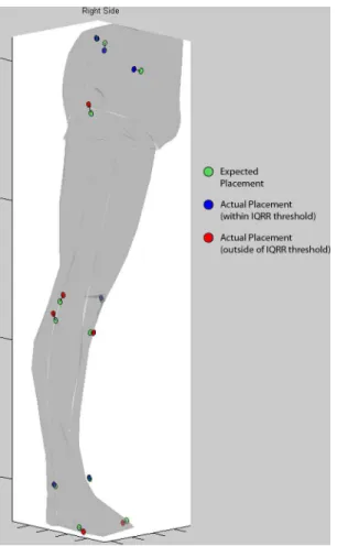
Fig 1. Feedback tool screenshot.Screenshot demonstrating feedback given to the Novices of the pilot study to indicate potential errors in marker placement. A lower-limb surface model was constructed and anatomical marker position data was overlaid to provide context for users (segment markers locations were identical for all trials, and therefore omitted). The marker position data consisted of expected positions (green circles), which were scaled to fit the surface model, and dimensionless IQRR scores (blue and red circles), which were scaled and positioned relative to the expected position with a connecting line to indicate directionality. Red circles indicated that a marker had crossed the threshold of 0.8 for the associated IQRR score, while blue circles indicated the marker was within the threshold. Participants were instructed to only modify those placements indicated by red circles, and to use their judgment in deciding how much to move the marker.
Knee and ankle markers demonstrated influence over the largest number of kinematic vari-ables, with trochanter markers and MTP markers influencing only a few variables (Fig 3). In terms of peak angles, the anteroposterior (AP) coordinates of the knee and ankle markers pro-duced the largest angular changes (up to 7.59 degrees/10 mm). In terms of angular velocities, errors in AP ankle markers produced the largest changes (up to 45.5 degrees per second/10 mm).
IQRR Classifier Evaluation
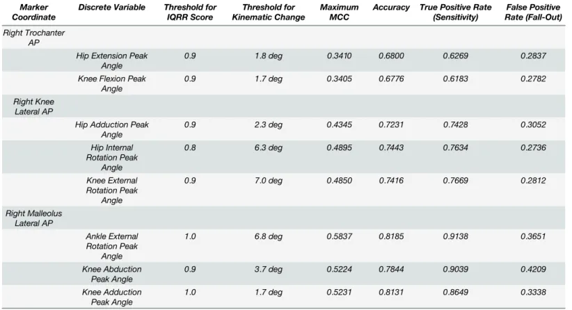
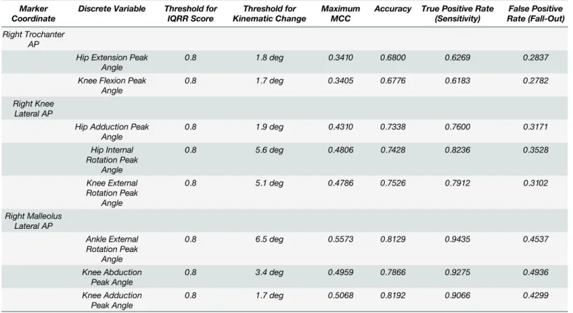
There was no single IQRR threshold that produced maximum MCCs across all variable/marker pairs, therefore maximum MCCs were identified for selected IQRR thresholds to evaluate potential performance benefits (Tables1–3). An IQRR threshold of 0.8 maximized true positive rates (sensitivity) across nearly all of the marker-coordinate pairs, whereas larger tradeoffs were apparent for other threshold criteria.
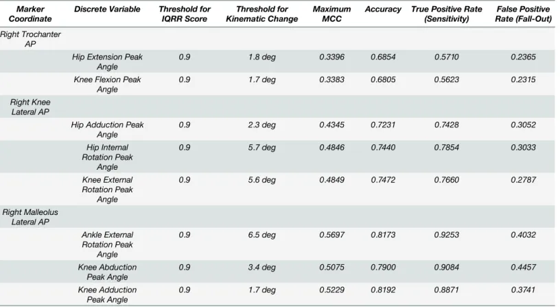
Each marker/variable pair was evaluated on IQRR thresholds from 0.0 to 1.0 (0.1 ments) and on kinematic change thresholds from 0.0 to the maximum value (0.1 degree incre-ments).Table 1includes results for the maximum MCC scores found across all threshold pairings.Table 2includes results when the IQRR threshold was fixed at 0.9 and maximum MCC was found for kinematic change.Table 3includes results when the IQRR was fixed at 0.8 and maximum MCC was found for kinematic change.
Real-World Pilot Study
Median deviation in kinematic variables between Novice testers and the Expert trended towards zero in 7 of the 9 kinematic variables after feedback was given (Fig 4). However, these differences were only significant for peak knee flexion and peak hip extension (family-wise
α= 0.05).
Fig 2. Relationships between marker errors and changes in discrete variables.Two basic relationships were observed: the left panel shows a highly linear relationship between anteroposterior marker placement error and kinematic change in the transverse plane, the right panel shows a non-linear relationship between vertical marker error and frontal plane kinematics.
Discussion
The purposes of this study were to: 1) use simulated deviations in marker placement to calcu-late resulting changes in downstream kinematic variables and quantify relationships between marker placement and changes in kinematic variables; 2) evaluate the classification perfor-mance of the IQRR score by considering MCCs, false positive (fall-out) and true positive (sen-sitivity) rates for a range of kinematic and IQRR thresholds; and 3) to conduct a real-world pilot study of the IQRR method. The results indicate large influences of malleolus and knee marker placement deviations on kinematics, along with favorable performance of the IQRR classifier in detecting markers placed in different (unexpected) locations.
It has previously been demonstrated that deviation in marker placement can affect many downstream variables [5], and that precision in the 3D coordinates of anatomical landmarks propagates into joint angle calculations for the lower limb [6,17]; however, specific
Fig 3. Tabulated results of the error sensitivity analysis.Values shown are for right side kinematics only, however, left side trends were nearly identical. All values for kinematic change ratios represent a point estimate of the 95th percentile ratio, using the mean of 10 iterations of the simulation. All values shown are in normalized units of degrees of error per 10 mm of marker error (for angles), or degrees/s of error per 10 mm of marker error (for angular velocities). Empty cells indicate that a variable changed less than 0.5 degrees, or 5 degrees/second, for every 10 mm of error.
relationships between the two have not been elucidated. According to current results, it is not only knee markers that can have a large influence over kinematic variables, but ankle marker placement as well. In both cases, the most affected joint angles were those in the transverse plane at the hip, knee and ankle, while the most affected velocities were in the frontal and trans-verse planes at the knee joint. These findings are consistent with experimental studies that have also highlighted the sensitivity of variables in the transverse plane [2,18,19]. Taken together, these results argue for caution in measuring kinematics of the transverse plane.
Previous studies have postulated that relationships between marker placement and gait kinematics arise from conventions in the creation of segment coordinate systems [1,6,17,20]. Indeed, it is likely that the conventions chosen will determine the propagation of deviations, and therefore, generalizations from the current findings must be interpreted in the context of the model used. For many segment-fixed joint coordinate systems (JCS), the joint centre and the hinge axis are defined using two markers on the lateral and medial sides of a joint, making these JCS hinges highly sensitive to anteroposterior deviations.
Since joint angles are calculated based upon orientations of the two segments they connect, the construction of either segment coordinate system may exert an influence over the calcu-lated joint angle. It is therefore understandable that malleoli markers influence ankle and knee transverse angles, but not hip angles, while knee markers primarily influence hip and knee transverse angles (Fig 3). Knee, ankle and hip markers also influence sagittal plane joint angles, and this effect likely arises from the construction of the long axes of segments based on the location of the proximal joint centres. Although this effect is much smaller than effects in other planes, it is worth noting that prior studies have demonstrated small but significant differences Table 1. Tabulated results of the evaluation of the IQRR as a classifier of placement deviation, using maximum MCC.
Marker Coordinate
Discrete Variable Threshold for IQRR Score
Threshold for Kinematic Change
Maximum MCC
Accuracy True Positive Rate (Sensitivity)
False Positive Rate (Fall-Out)
Right Trochanter AP
Hip Extension Peak Angle
0.9 1.8 deg 0.3410 0.6800 0.6269 0.2837
Knee Flexion Peak Angle
0.9 1.7 deg 0.3405 0.6776 0.6183 0.2782
Right Knee Lateral AP
Hip Adduction Peak Angle
0.9 2.3 deg 0.4345 0.7231 0.7428 0.3052
Hip Internal Rotation Peak
Angle
0.8 6.3 deg 0.4895 0.7443 0.7634 0.2736
Knee External Rotation Peak
Angle
0.9 7.0 deg 0.4850 0.7416 0.7669 0.2812
Right Malleolus Lateral AP
Ankle External Rotation Peak
Angle
1.0 6.8 deg 0.5837 0.8185 0.9138 0.3651
Knee Abduction Peak Angle
0.9 3.7 deg 0.5224 0.7844 0.9039 0.4209
Knee Adduction Peak Angle
1.0 1.7 deg 0.5231 0.8131 0.8649 0.3338
in sagittal plane joint angles between testers [1], and it is possible that these differences can be entirely accounted for by this mechanism.
Prior studies of placement deviation have asserted that marker placement deviations are unpredictable [17], and indeed, it is not eminently clear how these deviations occur. To this point, by using a large cohort this study provides near-worst-case 95thpercentile changes in a given kinematic variable in response to a 10 mm placement deviation. The standard value of 10 mm was chosen as this approximates one marker diameter (9.5 mm markers were used in this study). This‘rule-of-thumb’can be applied in context to provide an estimate of whether a kinematic difference might be spurious. As a simple example, if a researcher or clinician is con-fident they rarely deviate in malleoli markers by more than half-a-marker-width, then they can infer that a repeated measures difference in peak ankle rotation which exceeds 3.80 degrees would fall outside of the 95%ile error estimate (7.59 degrees/10 mm error x 1/2). It is critically important to qualify, however, that the validity of this approach is dependent upon the lower extremity model chosen by the investigators.
As a binary classifier of placement errors, the IQRR score shows promise as a means of devi-ation detection. The fixed IQRR threshold of 0.8 results in very good sensitivity (true positive rates of ~62–94%), with reasonably low corresponding thresholds for many discrete kinematic variables (Table 3). The specificity of the IQRR score is not as high (true negative rates of ~51– 72%), however this is not entirely unexpected. It is clear that the IQRR score does not reflect only deviations in placement, but rather a combination of deviation and unique anatomical configuration [4]. Given this feature of the analysis, and the high false positive (fall-out) rates, the results cannot be taken as an absolute measure of placement deviation, but rather as a valu-able training and reference tool.
Table 2. Tabulated results of the evaluation of the IQRR as a classifier of placement deviation, using an IQRR threshold of 0.9 and finding maxi-mum MCC.
Marker Coordinate
Discrete Variable Threshold for IQRR Score
Threshold for Kinematic Change
Maximum MCC
Accuracy True Positive Rate (Sensitivity)
False Positive Rate (Fall-Out)
Right Trochanter AP
Hip Extension Peak Angle
0.9 1.8 deg 0.3396 0.6854 0.5710 0.2365
Knee Flexion Peak Angle
0.9 1.7 deg 0.3383 0.6805 0.5623 0.2315
Right Knee Lateral AP
Hip Adduction Peak Angle
0.9 2.3 deg 0.4345 0.7231 0.7428 0.3052
Hip Internal Rotation Peak
Angle
0.9 5.7 deg 0.4846 0.7440 0.7854 0.3033
Knee External Rotation Peak
Angle
0.9 5.6 deg 0.4849 0.7472 0.7660 0.2787
Right Malleolus Lateral AP
Ankle External Rotation Peak
Angle
0.9 6.5 deg 0.5697 0.8173 0.9253 0.4032
Knee Abduction Peak Angle
0.9 3.4 deg 0.5075 0.7900 0.9084 0.4457
Knee Adduction Peak Angle
0.9 1.7 deg 0.5229 0.8192 0.8871 0.3741
Pilot data using placement feedback demonstrated that a group of Novices with no biome-chanics experience were able to immediately reduce their median deviation from the Expert by up to ~80% for knee sagittal kinematics. In two individual cases, there were consistent
Fig 4. Results of the pilot study.Bars indicate the signed median difference between the group of n = 6 Novices and the Expert, both before and after receiving feedback.*indicates significant differences from the Signed Wilcoxon Rank test (family-wise p<0.05).
doi:10.1371/journal.pone.0147111.g004
Table 3. Tabulated results of the evaluation of the IQRR as a classifier of placement deviation, using an IQRR threshold of 0.8 and finding maxi-mum MCC.
Marker Coordinate
Discrete Variable Threshold for IQRR Score
Threshold for Kinematic Change
Maximum MCC
Accuracy True Positive Rate (Sensitivity)
False Positive Rate (Fall-Out)
Right Trochanter AP
Hip Extension Peak Angle
0.8 1.8 deg 0.3410 0.6800 0.6269 0.2837
Knee Flexion Peak Angle
0.8 1.7 deg 0.3405 0.6776 0.6183 0.2782
Right Knee Lateral AP
Hip Adduction Peak Angle
0.8 1.9 deg 0.4310 0.7338 0.7600 0.3171
Hip Internal Rotation Peak
Angle
0.8 5.6 deg 0.4806 0.7428 0.8236 0.3528
Knee External Rotation Peak
Angle
0.8 5.1 deg 0.4786 0.7526 0.7912 0.3102
Right Malleolus Lateral AP
Ankle External Rotation Peak
Angle
0.8 6.5 deg 0.5573 0.8129 0.9435 0.4537
Knee Abduction Peak Angle
0.8 3.4 deg 0.4959 0.7866 0.9275 0.4936
Knee Adduction Peak Angle
0.8 1.7 deg 0.5068 0.8192 0.9066 0.4299
reductions, of up to 11 degrees, in deviations from Expert kinematics. This result, however, was not universal, and there appeared to be a tendency in two other Novices to over-adjust their placements. Further work is therefore needed to optimize feedback and to study longitudinal learning trends over many uses of the feedback tool. Future studies involving: a larger sample of novice users, multisite comparisons, and dynamic events other than running gait are also necessary.
A principal limitation of the current study is the reference database from which the feedback were generated. The nature of this reference database will define the limits of its applicability in terms of specific morphologies (i.e. developmental disorders, surgical changes, diseases affect-ing bone structure). However, while this method may currently be limited in application to a population of morphologically average individuals, the database may easily be scaled to include more individuals as data are collected on them. This is a significant strength of the current method, as the database will continue to evolve and expand as the method is applied in practice.
In conclusion, important and identifiable relationships exist between marker placement deviations and downstream kinematics, placement classification based on the IQRR score detected up to 94% of simulated deviations, and pilot testing of a placement feedback tool by Novices resulted in significant reductions in their deviation from results obtained by the Expert. Thus, the current study supports the use of placement deviation detection and feed-back, and speaks to the need for future research in evaluating the utility and optimal applica-tion of this approach.
Supporting Information
S1 Dataset. Comprehensive results from iteration 1 of the simulation experiment.Each iter-ation of the simuliter-ation is saved as a separate file. Within each file, individual spreadsheets con-tain data from each subject. Within each spreadsheet, rows 3–30 contain calculated discrete variables from the unaltered trials and with errors added to each marker/coordinate, and rows 34–60 contain IQRR scores from the marker placement GPA calculations.
(XLSX)
S2 Dataset. Comprehensive results from iteration 2 of the simulation experiment. (XLSX)
S3 Dataset. Comprehensive results from iteration 3 of the simulation experiment. (XLSX)
S4 Dataset. Comprehensive results from iteration 4 of the simulation experiment. (XLSX)
S5 Dataset. Comprehensive results from iteration 5 of the simulation experiment. (XLSX)
S6 Dataset. Comprehensive results from iteration 6 of the simulation experiment. (XLSX)
S7 Dataset. Comprehensive results from iteration 7 of the simulation experiment. (XLSX)
S8 Dataset. Comprehensive results from iteration 8 of the simulation experiment. (XLSX)
S10 Dataset. Comprehensive results from iteration 10 of the simulation experiment. (XLSX)
Author Contributions
Conceived and designed the experiments: STO BAH RF. Performed the experiments: STO SM. Analyzed the data: STO BAH. Contributed reagents/materials/analysis tools: STO BAH. Wrote the paper: STO BAH SM RF.
References
1. Gorton GE 3rd, Hebert DA, Gannotti ME. Assessment of the kinematic variability among 12 motion analysis laboratories. Gait & Posture. 2009; 29(3): 398–402.
2. McGinley JL, Baker R, Wolfe R, Morris ME. The reliability of three-dimensional kinematic gait measure-ments: A systematic review. Gait & Posture. 2009; 29(3): 360–369.
3. Wilken JM, Rodriguez KM, Brawner M, Darter BJ. Reliability and minimal detectible change values for gait kinematics and kinetics in healthy adults. Gait & Posture. 2012; 35(2): 301–307.
4. Osis ST, Hettinga BA, Macdonald SM, Ferber R. A novel method to evaluate error in anatomical marker placement using a modified generalized Procrustes analysis. Computer Methods in Biomechancis and Biomedical Engineering. 2014; 18(10): 1108–1116.
5. Szczerbik E, Kalinowska M. The influence of knee marker placement error on evaluation of gait kine-matic parameters. Acta of bioengineering and biomechanics / Wrocław University of Technology. 2011; 13(3): 43–46. PMID:22098124
6. Della Croce U, Cappozzo A, Kerrigan DC. Pelvis and lower limb anatomical landmark calibration preci-sion and its propagation to bone geometry and joint angles. Medical & Biological Engineering & Com-puting. 1999; 37(2): 155–161.
7. Pohl MB, Lloyd C, Ferber R. Can the reliability of three-dimensional running kinematics be improved using functional joint methodology? Gait & Posture. 2010; 32(4): 559–63.
8. Mills K, Hettinga BA, Pohl MB, Ferber R. Between-limb kinematic asymmetry during gait in unilateral and bilateral mild-to-moderate knee osteoarthritis. Archives of Physical Medicine and Rehabilitation. 2013; 94(11): 2241–2247. doi:10.1016/j.apmr.2013.05.010PMID:23747645
9. Weinhandl JT, O’Connor KM. Assessment of a greater trochanter-based method of locating the hip joint center. Journal of Biomechanics. 2010; 43(13): 2633–2636. doi:10.1016/j.jbiomech.2010.05.023
PMID:20605153
10. Cole GK, Nigg BM, Ronsky JL, Yeadon MR. Application of the joint coordinate system to three-dimen-sional joint attitude and movement representation: a standardization proposal. Journal of Biomechani-cal Engineering. 1993; 115: 344–349. PMID:8309227
11. Stagni R, Leardini A, Cappozzo A, Benedetti MG, Cappello A. Effects of hip joint centre mislocation on gait analysis results. Journal of Biomechanics. 2000; 33(11): 1479–1487. PMID:10940407
12. Söderkvist Wedin. Determining the Movements of the Skeleton Using Well-configured Markers. Journal of Biomechanics. 1993; 26: 1473–1477. PMID:8308052
13. Ferber R, Davis IM, Williams DS 3rd. Gender differences in lower extremity mechanics during running. Clinical Biomechanics. 2003; 18(4): 350–7. PMID:12689785
14. McClay I, Manal K. Three-dimensional kinetic analysis of running: significance of secondary planes of motion. Medicine and Science in Sports and Exercise. 1999; 31(11): 1629–37. PMID:10589868
15. Phinyomark A, Hettinga BA, Osis ST, Ferber R. Gender and age-related differences in bilateral lower extremity mechanics during treadmill running. PLoS One. 2014; 9(8): e105246. doi:10.1371/journal. pone.0105246PMID:25137240
16. Wolf P, List R, Ukelo T, Maiwald C, Stacoff A. Day-to-Day consistency of lower extremity kinematics during walking and running. Journal of Applied Biomechanics. 2009; 25(4): 369–76. PMID:20095458
17. Della Croce U, Leardini A, Chiari L, Cappozzo A. Human movement analysis using stereophotogram-metry: Part 4: assessment of anatomical landmark displacement and its effects on joint kinematics. Gait & Posture. 2005; 21(2): 226–237.
19. Schwartz MH, Trost JP, Wervey RA. Measurement and management of errors in quantitative gait data. Gait & Posture. 2004; 20(2): 196–203.