1 INTRODUCTION
National standards with design rules for stiffened flanges used in steel box girder bridges were almost non-existent until the early nineteen seventies. These design rules were based on the elastic critical stress (σcr) obtained by the linear buckling theory of plates with some correction
factors to take into account the favorable effect of the post-critical strength reserve (ECCS Committee8 1976).
Research work to establish new design rules for plated structures was strongly increased in the early nineteen seventies as a result of well-known accidents during construction involving box girder bridges (Galambos 1998). Although the behavior and strength of stiffened plates have been extensively studied over the last forty years, there are still some inconsistencies and gaps between the results of some studies and the results obtained through the design rules es-tablished in the European and American standards (EN-1993-1-5 2006, AASHTO-LRFD-BDS 2007), which are usually adopted by the bridge designers to solve the problem of predicting the ultimate strength of stiffened plates.
In wide flanges and webs of considerable height it is common to use longitudinal stiffeners to reduce the problems associated with the effects of buckling.
The study of the behavior and strength of steel plates with longitudinal stiffeners is very complex because they depend on a large number of variables, such as the shape and amplitude of the initial geometric imperfections, the residual stresses, the boundary conditions for the in-plane and out-of-in-plane displacements, the load conditions and the geometric and material data. Recent numerical studies (Ferreira 2012, Braun 2010) showed that the behavior and strength of steel plates are very sensitive to in-plane displacements boundary conditions and the European and American standards (EN-1993-1-5 2006, AASHTO-LRFD-BDS 2007) do not provide a definition and clear guidance for the proper use of the simplified rules available to designers. These rules may give considerable errors, particularly when applied to the safety verification of stiffened plates where the transverse in-plane displacements at longitudinal edges cannot be considered as uniform (in-plane displacements perpendicular to the longitudinal edges
con-Stiffened flanges used in steel box girder bridges
P.S. Ferreira
Polytechnic Institute of Setubal, Escola Superior de Tecnologia do Barreiro and ICIST, Setubal, Portugal
F. Virtuoso
University of Lisbon, Instituto Superior Técnico, DECivil-ICIST, Lisbon, Portugal
strained to remain straight).
In European standard (EN-1993-1-5 2006) the resistance assessment of webs and internal flanges with longitudinal stiffeners used in steel box girder bridges is performed through the same criterion and independent of the in-plane displacement boundary conditions of the plate. Just apparently both elements may have the same in-plane displacement boundary conditions. Indeed, the webs are usually connected to flanges that possess sufficient rigidity to consider uniform the in-plane displacements at longitudinal edges, while the flanges are connected to webs that usually do not provide this type of constraint and it is more conservative to consider free the in-plane displacements at longitudinal edges, as shown in the work of Ferreira & Virtu-oso (2011) through a comparison between numerical and experimental results.
The design proposal presented in this paper for stiffened flanges aims to fill a gap in the cur-rent European bridge design rules, which should not be applied to stiffened plates with the fully free transverse in-plane displacements at longitudinal edges.
2 DESIGN PROPOSAL
The design proposal is a model based on design curves (arithmetic expressions) describing the influence of all relevant parameters on the ultimate strength of stiffened flanges used in steel box girder bridges. It was developed and calibrated based on the results obtained with the semi-analytical and finite element methods and it was validated by comparison with the results of experimental test in accordance with the target failure probability of EN-1990 (2002).
These design curves consider that the plate is subject to compressive longitudinal direct stress with a stress ratio higher than 0.5 (lower compressive longitudinal stress to the higher compressive longitudinal stress ratio, ψ>0.5), the transverse stiffeners provide rigid support lines, the longitudinal stiffeners are fully effective and equally spaced and the plates have the longitudinal in-plane displacements constrained to remain straight at loaded edges (transverse edges) and the other in-plane displacements fully free. This design model does not consider the effects of local buckling of the stiffener elements and tripping of the stiffener. These effects can be avoided by adopting minimum values for the geometric properties of the longitudinal stiff-eners as used in European and American standards (EN-1993-1-5 2006, AASHTO-LRFD-BDS 2007).
The design proposal is a design approach based on the reduced section concept, where the mean compressive stress at peak load (or ultimate strength σu) of a stiffened plate is estimated
through the yield strength of the effective cross-sectional area according to
A A
f
loc , eff glob y
u =ρ σ
(1) where fy = yield stress; ρglob = global reduction factor; Aeff,loc = effective local cross-sectional ar-ea which takes into account the local buckling effects; and A = gross cross-sectional arar-ea of the stiffened plate.
From Equation 1 it can be noted that the effective cross-sectional area (Aeff = ρglob.Aeff,loc)
which takes in-to account the local and global buckling effects is obtained by reducing the cross-sectional area of the stiffened plate in two different steps, as illustrated in Figure 1.
In the first step the effect of local buckling in the panels between longitudinal stiffeners is taken into account and an effective width of these panels is adopted to obtain an effective local cross-sectional area (Aeff,loc) according to
(
)
st sln
i
i i , p i , loc loc
,
eff
b
t
n
A
A
st
+
ρ
=
∑
+1 (2)un-favorable effects of the initial imperfections and it is defined for each panel between longitudi-nal stiffeners by
(
)
1 3 055 0 2 ≤ λ ψ + − λ = ρ norm , p norm , p loc . (3) where λp,norm = relative slenderness of the panels. For a relative slenderness of the panels lowerthan 0.673 the local reduction factor should be considered equal to 1. Equation 3 is the same criterion used in European standard (EN-1993-1-5 2006).
Figure 1. Reduction of the cross-sectional area of a stiffened plate in the design proposal: (a) the gross cross-sectional area, (b) the effective local cross-sectional area and (c) the effective cross-sectional area.
In the second step, which takes into account the effect of global buckling in the stiffened plate, a global reduction factor (ρglob) is considered to reduce the effective local cross-sectional
area (Aeff,loc). The global reduction factor is given by
(
χ ρ ∞)
=
ρglob max c; p, (4)
where χc = reduction factor for the column buckling behavior; and ρp,∞ = reduction factor for
the plate buckling behavior estimated for a long stiffened plate (stiffened plate where the elastic critical stress σcr no longer depends of the plate length a).
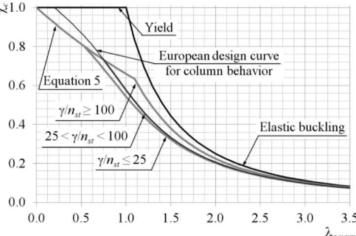
Column buckling behavior is considered in stiffened plates with insignificant post-critical re-sistance. This behavior is modeled by removing the supports along the longitudinal edges of the plate and considering the cross-section of the column equivalent to the plate composed of a sin-gle stiffener with an effective width of the adjacent panels to the stiffener. The reduction factor for the column buckling behavior is obtained by
1 1 66 0 min 2
2 ≤
λ − φ + φ = χ λ norm , c c c
c . ;
norm ,
c (5)
where λc,norm = relative slenderness of the equivalent column; and φc = parameter that depends
on the initial imperfections, the relative slenderness of the equivalent column (λc,norm), the
rela-tive flexural stiffness of the stiffened plate γ (second moment of area of the stiffened plate Ist to the second moment of area for bending of the plate corrected by the effect of the Poisson coef-ficient (bt3/[12(1-ν2)]) ratio) and the number of longitudinal stiffeners (n
st).
The first term in Equation 5 (0.66λc,norm) is the critical criterion in stiffened flanges with low
values of equivalent column relative slenderness (λc,norm) and it is equal to the reduction factor
established in the American standard (AASHTO-LRFD-BDS 2007) for the column buckling behavior of stiffened plates. The other term in Equation 5 is the determinant criterion in stiff-ened plates with intermediate and high values of equivalent column relative slenderness (λc,norm)
Figure 2 presents the reduction factor for the column buckling behavior (χc) obtained using
the design proposal. It is also shown the yield, the elastic buckling and the European standard criteria. An equivalent geometric imperfection of 1/400 of the plate length (a) was used.
Figure 2. Reduction factor for the column buckling behavior obtained using the design proposal.
Plate buckling behavior is considered in stiffened plates with post-critical resistance. The de-sign proposal uses this type of behavior to define the minimum ultimate strength of the stiff-ened plate, which is estimated considering a long plate. The reduction factor for the plate buck-ling behavior of a long stiffened plate is obtained by
ξ > λ ≤
λ ξ − λ
ξ ≤ λ ≤
ξ =
ρ ∞
2 1
1
2 1
4 1
2 p,norm
norm , p norm , p
norm , p
, p
for for
(6)
where λp,norm = relative slenderness of the stiffened plate; and ξ = parameter that depends on the
compressive longitudinal stress ratio (ψ), the panel slenderness λp (width of the panels between
stiffeners bp to the plate thickness t ratio), the relative cross-sectional area δ (cross-sectional ar-ea of the stiffeners without any contribution of the plate nst.Asl to the cross-sectional area of the plate (bt) ratio), the relative flexural stiffness of the stiffened plate (γ) and the number of longi-tudinal stiffeners (nst).
The reduction factor for the plate buckling behavior estimated for a long stiffened plate (ρp,∞)
is governed by the parameter ξ and Equation 6 becomes the well-known criterion proposed by Winter when this parameter is equal to 0.22. Based on the geometric parameters of the stiffened flanges identified in the survey of stiffened flanges used in real steel box girder brides present-ed in Ferreira (2012) the minimum and maximum values of the parameter ξ are 0.19 and 0.64 respectively.
Figure 3 presents the reduction factor for the plate buckling behavior of a long stiffened plate (ρp,∞) obtained using the design proposal with different values of the parameter ξ. It is also
shown the yield, elastic buckling and Winter criteria.
Figure 3 shows that the application of the design proposal results in a lower ultimate strength (σu) of the stiffened flange with fully free in-plane displacements at longitudinal edges than that
obtained by the current European bridge design rules, which is consistent with the results ob-tained using nonlinear finite element simulations and with the results of experimental tests pre-sented in the works of Ferreira & Virtuoso (2010, 2011).
The complete definition of the procedures and variables used in the design proposal and the statistical evaluation using experimental test and numerical results within the framework of a probabilistic reliability theory in accordance with EN-1990 (2002) can be found in the work of Ferreira (2012). It is noted that the numerical value for the partial safety factor (γM) obtained
(EN-1993-2 2006).
Figure 3. Reduction factor for the plate buckling behavior obtained using the design proposal with differ-ent values of the parameter ξ.
3 RESULTS, DISCUSSION AND CONCLUSIONS
The comparison between the ultimate strength (σu) obtained using the design proposal with that
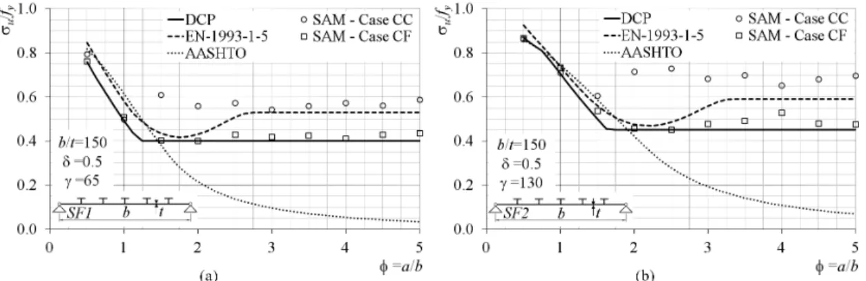
obtained using nonlinear analyses and current bridge design rules established in the European and American standards (EN-1993-1-5 2006, AASHTO-LRFD-BDS 2007) was performed con-sidering 20 stiffened flanges. The 20 stiffened flanges were obtained based on two types of cross-sections, SF1 and SF2, and considering for each cross-section the plate aspect ratio φ (=a/b) ranging from 0.5 to 5.0 at intervals of 0.5. Both cross-sections have five longitudinal equally spaced and single sided stiffeners, the stiffened flanges with the cross-section SF1 have a relative flexural stiffness γ (=12Ist(1-ν2)/(bt3)) of 65 and the stiffened flanges with the cross-section SF2 have a relative flexural stiffness γ of 130. All stiffened flanges have a relative cross-sectional area δ (=Asl/(bt)) of 0.5, plate slenderness λplt (=b/t) of 150 and panel
slender-ness λp (=bp/t) of 25.
The nonlinear analyses were performed using the semi-analytical model presented in the work of Ferreira (2012) and considering a yield stress (fy) of 355 Nmm-2, Young's modulus (E) of 2.1x10⁵ Nmm-2 and Poisson's coefficient (ν) of 0.3.
The stiffened flanges were considered simply supported under longitudinal uniform com-pression (σ) with the following two cases for the in-plane displacement boundary conditions: in-plane displacements perpendicular to the edges constrained to remain straight in all edges (case CC) and in-plane displacements perpendicular to the edges constrained to remain straight at loaded edges and free at unloaded edges (case CF).
Figure 5 presents the comparison between the ultimate strength (σu) obtained by the design
proposal, the semi-analytical model and current bridge design rules. Figure 5a shows the mate strength for the stiffened flanges with the cross-section SF1 and Figure 5b shows the ulti-mate strength for the stiffened flanges with the cross-section SF2. The results are presented in terms of normalized strength (mean compressive stress at peak load σu to the yield stress fy ra-tio) for different values of the plate aspect ratio φ (=a/b).
From the analysis of Figure 5 it can be noted that the ultimate strength (σu) obtained by the
design proposal presents a much better agreement with the nonlinear analysis results obtained by the semi-analytical model considering the case CF for the in-plane displacement boundary conditions than the ultimate strength obtained by the current bridge design rules. This observa-tion is particularly clear in the case of long plates, where the design rules established by the Eu-ropean standard leads to nonconservative results and the design rules established by the Ameri-can standard leads to extremely conservative results.
The design proposal predicts the ultimate strength (σu) in a quick and simple way and
Figure 5. Comparison between the ultimate strength obtained by the design proposal (DCP), the semi-analytical model (SAM) and current bridge design rules for the stiffened flanges with the cross-section: (a) SF1 and (b) SF2.
ACKNOWLEDGEMENTS
This work was carried out in the framework of the research activities of ICIST, Instituto de Engenharia de Estruturas, Território e Construção and was funded by FCT, Fundação para a Ciência e Tecnologia.
REFERENCES
AASHTO-LRFD-BDS. 2007. AASHTO LRFD Bridge Design Specification. Washington: American As-sociation of State Highway and Transportation Officials.
Braun, B. 2010. Stability of steel plates under combined loading. PhD thesis. Stuttgart: University of Stuttgart.
ECCS Committee8. 1976. Manual on Stability of Steel Structures. ECCS publication 22. Brussels: ECCS. EN 1990. 2002. Eurocode – Basis of structural design. Brussels: European Committee for
Standardiza-tion.
EN-1993-1-5. 2006. Eurocode 3 – Design of Steel Structures – Part 1-5: Plated Structural Elements. Brus-sels: European Committee for Standardization.
EN-1993-2. 2006. Eurocode 3 – Design of Steel Structures –Part 2: Steel Bridges. Brussels: European Committee for Standardization.
Ferreira, P. 2012. Stiffened compression flanges of steel box girder bridges: postbuckling behaviour and ultimate strength. Ph.D thesis. Lisbon: Instituto Superior Técnico, Technical University of Lisbon. Ferreira, P. & Virtuoso, F. 2011. Efeito do tipo de restrição nos bordos longitudinais no comportamento e
resistência de placas metálicas em pontes. In L. Simões da Silva, P. Cruz, N. Lopes, J. Fernandes, and A. Baptista (ed.), Proceedings of the 8th Conference on Steelwork Construction, Guimarães, 24-25 November 2011. Coimbra: CMM and University of Minho. (in Portuguese)
Ferreira, P. & Virtuoso, F. 2010. Collapse load of box flanges with longitudinal stiffeners under uniform compression: comparative study of EC3 and AASHTO LRFD bridge design rules with nonlinear finite element analysis. In N. Yardimci, B. Aydöner, Y. Gür'es, and C. Yorgun (ed.), Proceedings of the In-ternational Symposium on Steel Structures: Culture & Sustainability, Istanbul, 21-23 September 2010. Istanbul: TUCSA and ECCS.