Photovoltaic Powered Water Pumping Systems: Design and Optimization of an Irrigation System
UNIVERSIDADE DE LISBOA
FACULDADE DE CIÊNCIAS
DEPARTAMENTO DE ENGENHARIA GEOGRÁFICA, GEOFÍSICA E ENERGIA
Photovoltaic Powered Water Pumping Systems:
Design and optimization of an irrigation system
Maria Inês Cardoso Bexiga
Dissertação de Mestrado
Maria Inês Cardoso Bexiga 2
UNIVERSIDADE DE LISBOA
FACULDADE DE CIÊNCIAS
DEPARTAMENTO DE ENGENHARIA GEOGRÁFICA, GEOFÍSICA E ENERGIA
Photovoltaic Powered Water Pumping Systems:
Design and optimization of an irrigation system
Maria Inês Cardoso Bexiga
Dissertação de Mestrado
Mestrado Integrado em Engenharia da Energia e do Ambiente
Trabalho realizado sob a supervisão de
José Carlos Amador (Martifer Solar)
João Serra (FCUL)
Abstract
This work has the objective of studying the possible application of photovoltaic solar energy to supply water pump systems.
It was suggested by Martifer Solar to size an irrigation photovoltaic water pumping system. This system is studied for the location of the headquarters of the company, in Oliveira de Frades, Portugal. The total area to irrigate was 16,119 m2.
A state-of-the art was made first, where advantages and different applications of these systems were presented. After, the methodology is described as a guide to sizing and optimize solar water pumping systems.
For that sizing, a multi-step method was used presented in Firatoglu et al. [1]. First, water demand was studied. Because it is a grass field, values of water daily demand change from 15m3 to 80m3, depending on the month. After, average data from solar resource was studied. The first conclusion to achieve was that water demand changes seasonally in a similar way as solar radiation available. A match between PV array and motor/pump assembly was made, through the study of manufacturer’s data of the different components. Curves from maximum power point and equilibrium operation point were calculated. The main goal is to match as much as possible both curves, with no use of any electronic controller. The modulation of the system was made using Matlab.
After the study of several configurations, it was concluded that the system would have 14 PV panels, (2S×7P) with a DC motor with Kv=0.18 V/rpm and Ra=0.50Ω and storage water tanks. It is assured that water demand is fulfilled throughout the year.
Resumo
Este trabalho tem como âmbito o estudo da possibilidade do uso de energia solar fotovoltaica em sistemas de bombagem de água.
Foi sugerido pela Martifer Solar o dimensionamento de um sistema de irrigação para um relvado situado na sede da empresa, em Oliveira de Frades, Portugal. A área total do relvado é 16,119m2. Inicialmente foi feito o estado da arte, onde foram discutidas as várias aplicações destes sistemas e as suas vantagens. De seguida, é descrita uma metodologia de dimensionamento, servindo como um guia para dimensionar e otimizar um sistema solar de bombagem de água.
Para o dimensionamento foi abordado um método apresentado em Firatoglu et al. [1]. Primeiro foi estudada a quantidade de água necessária para a irrigação. Por se tratar de um relvado, a quantidade diária de água necessária varia ao longo dos meses desde 15m3 até 80m3. Depois, foi estudado o recurso solar para o local. Foi logo concluído que a variação da quantidade de água necessária varia de forma semelhante com a radiação solar disponível.
Através do estudo de parâmetros dos vários componentes, foi feita uma correspondência entre os módulos fotovoltaicos e o motor/bomba. Foram calculadas curvas de potência máxima e curvas de pontos de equilíbrio. O principal objetivo é modelar, usando o Matlab. as duas de forma a ficaram o mais próximas possível, sem o uso de qualquer controlador eletrónico.
Após o estudo de várias configurações ficou concluído que o sistema seria constituído por 14 módulos fotovoltaicos(2S×7P, com um motor com os parâmetros Kv=0.18 V/rpm e Ra=0.50Ω e com tanques de armazenamento de água. A quantidade de água necessária fica assegurada ao longo de todo o ano.
Index
Abstract ...1 Keywords: ...1 Resumo ...2 Palavras-chave: ...2 1. Introduction ...8 1.1. Presentation ...8 1.2. Water supply ...8 1.3. Motivation ...8 1.4. Scope ... 10 1.5. Methodology ... 102. State of the Art ... 11
2.1. Applications of PV water pumping systems ... 11
2.2. Performance of a solar photovoltaic water pumping system – literature review... 12
2.3. Advantages of PV powered pumping ... 15
2.4. Pumping system basic operation and components ... 15
2.5. Pump Sets ... 17
2.6. Market of solar water pumps ... 19
3. Design and optimization of a solar water pump system ... 20
3.1. Available Solar energy and PV location ... 20
3.2. Water requirement ... 21
3.3. Water source ... 21
3.4. System layout ... 21
3.4.1. Direct-coupled system... 21
3.7.1. Centrifugal Pumps ... 26
3.7.2. Positive displacement pumps ... 32
3.8. Types of motors ... 37
3.9. Estimation of the Energy Demand... 37
3.10. Method for optimal PV pumping system ... 39
3.11. Maintenance ... 42
3.12. Limitations of Solar Powered Water Pumping Systems ... 42
4. Case of Study ... 43
4.1. Area and Location ... 43
4.2. Water Needs ... 43
4.3. Hydraulic Power ... 45
4.4. Configuration of the system ... 47
5. Conclusions ... 53
5.1. The future of PV water-pumping systems ... 53
5.2. Case of study conclusions/Discussion ... 54
6. References ... 55
Appendix A : Location Plan ... 58
Appendix B : Average Water Depth for Portugal ... 59
Appendix C : Matlab File ... 60
Appendix D : Lorentz motor-pump ... 61
Figure Contents
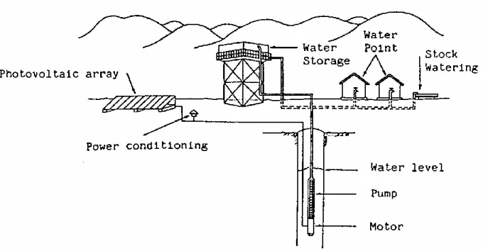
Figure 1 – Example of a Village Water Supply System ... 11
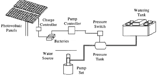
Figure 2 – Example of an irrigation system ... 12
Figure 3 - Block diagram of PV-powered water pumping system (dashed line means optional components) ... 16
Figure 4 - Surface suction pump-set ... 18
Figure 5 - Submersible pump and motor ... 18
Figure 6 - Floating motor and pump ... 18
Figure 7 - Submersible Pump and surface motor ... 18
Figure 8 - Long-term average solar irradiation (source: http://solargis.info/) ... 20
Figure 9 - direct-coupled system ... 22
Figure 10 - Battery-coupled system ... 23
Figure 11 – Negative Suction Head ... 24
Figure 12 - Positive Suction Head ... 24
Figure 13 - Well water levels ... 25
Figure 14 - Centrifugal pump ... 27
Figure 15 - Centrifugal Pump Diffuser ... 27
Figure 16 - Radial flow centrifugal pump ... 28
Figure 17 - Axial flow centrifugal pump ... 28
Figure 18 - Mixed flow centrifugal pumps ... 29
Figure 19 - Multi-stage centrifugal pump ... 29
Figure 20 - Centrifugal pump characteristic curve (example) ... 30
Figure 21 - Reciprocating Positive Displacement Pump Operation ... 32
Figure 22 - Simple Gear Rotary Pump ... 33
Figure 23 - Diaphragm Pump ... 34
Figure 24 - Positive Displacement Curve Characteristic Curve – Example ... 34
Figure 25 - Performance Chart [34] ... 35
Figure 26 - Idealized, actual Centrifugal and Positive Displacement Curves [34] ... 35
Figure 27 - Different pumps for different situations[36] ... 36
Figure 28 - Hydraulic Energy for different volume requirements ... 38
Figure 29 - The deviation between MPP and EOP curves of the system (reproduced only for discussion purpose) ... 41
Figure 34 - IV curve for different radiations (from 100W/m2 to 1000W/m2 with a 100W/m2 step) ... 47 Figure 35 - Operation characteristics of the system for three different cases (7P×2S) (from 100W/m2 to 1000W/m2 with a 100W/m2 step) ... 48 Figure 36 - Operation characteristics of the system for three different cases (8P×2S) (from 100W/m2 to 1000W/m2 with a 100W/m2 step) ... 49 Figure 37 – Operation characteristics for case 2 and 4 for 7P×2S PV configuration ... 50 Figure 38 -Operation characteristics for case 2 and 4 for 8P×2S PV configuration (from 100W/m2 to 1000W/m2 with a 100W/m2 step) ... 51 Figure 39 - Tank for water storage - T10500 model ... 52
Table Contents
Table 1 - Summary of principal advantages and disadvantages for diesel, wind and solar-powered
pumps [7] ... 10
Table 2 - Summary of investigations on SPWPSs ... 13
Table 3 - Summary table for chosen pump ... 36
Table 4 - Irradiation in Oliveria de Frades [kWh/m2/day] ... 43
Table 5 - Water needs for grass [42] ... 44
Table 6 - Different combinations of Kv and Ra... 48
1. Introduction
1.1. Presentation
Electricity is one of most versatile forms of energy and the one that better adapts to the actual world needs. Modern society way of life would have not been possible without electric energy and its use in a large scale. There are innumerous of machines that work with electric energy. However, a big amount of diesel and other fossil fuels generators are still working around the world, and it still is a solution for a lot of applications. Its use results in a dependence on fossil fuels leading to several environmental problems, not only in its operation but also on the refinery and transport of these fuels. In many cases, the use of fossil fuels appears in remote areas, where electric grid connection is difficult, expensive and sometimes impossible. In addition, the price of fossil fuels is very unstable and the increasing trend is evident for the last decade [2].
Therefore, renewable energies such as solar, wind, hydropower, and biomass and geothermal are potential sources to supply global energy demand in a sustainable way, introducing an alternative that can overcome the problems of costs of energy, energy supply and pollution [3]. Renewable energies can lead to an increasing of the energy supply security.
1.2. Water supply
Water is essential to life. Water consumption is not only made in a direct way but is also needed for food production, cleaning, sanitation and other domestic and industrial functions.
An important part of the world population lives in a rural environment where the lack of infrastructures is stimulating an exodus to urban centers or more developed regions [2]. Maintenance of rural populations is needed in order to attend to several necessities.
Lack of water or its bad quality can cause severe sanitation, nutritional and economic problems to affected populations. As well as access to water is critical for the survival of human beings, the good use of it is also critical in equal measure. Due to the sustainability of the water resource, water extraction may not be bigger than its natural replacement [2].
The first priority is the supply of drinkable water for the consumption on the population itself, for domestic animals and, when necessary, for agriculture. Unfortunately, it is usual in several regions of the planet that people need to walk several kilometers to find water, and in the majority of these cases, water quality is poor.
1.3. Motivation
There is energy consumption in every step of supply, treatment and use of water. The intensity of energy consumptions depends on which technology its used for each process. Infrastructures that supply water for agriculture, domestic consumption or sanitation use systems of treatment and distribution that require significant amounts of energy.
Generally, the water supply problem is related to the local energy deficit to execute extraction and transportation work from the source to the place of the consumption. Therefore, the solution for this could be the introduction of off-grid systems of energy production, since the electric grid extension can be very expensive in comparison to other alternatives.
All over the world, electrical and diesel-powered water pumping systems are widely used for irrigation or village supply applications. The problems mentioned above about the use of conventional energy
sources have created an interest in choosing renewable energy sources to power water pumping systems since these energy resources are available anywhere [4].
Water pumping systems are known since the primordial times, where the systems were manual or based on animal traction. After that, pumps using diesel motors became very popular, however, besides the fuel prices, availability and environmental problems, they require frequent maintenance. Pumps that work using wind energy, besides the unnecessary supply of fuel, have their use limited to wind conditions that are difficult to predict. Usually the term “wind powered pumps” refers to wind mills that use the wind to mechanically extract water from a well. The use of a wind turbine to produce electric energy to then power the water pump is not yet very common. However, these systems are now starting to be used and are being financed in some locations by state institutions [5]. Before applying wind turbines the local wind data should be carefully measured and analysed. It is possible that the terrain morphology may reduce more than expected the energy output. However, if the wind speed is actually higher than expected most likely the output will increase roughly exponentially. Solar pumps are recent (the firsts were installed in the 70’s [2]) and they are less known, but PV pumping systems present one of the most interesting and potentially cost-effective applications, used for cover both irrigation needs and drinkable water supply, including also the prospect of desalination [6].
Solar water pumping is done all over the world and greatly enhances the quality of life of people's living in rural and remote communities. A solar water pumping system does not have to use batteries to provide the power as the pump will operate during the day by pumping water into a tank for use at night.
The variety of water pumping applications is considerable and they can vary widely, both in their requirements and the conditions under which water must be pumped. Volume of required water, capacity of the source to deliver the water, depth from which the water is pumped, season and time of the pumping, and most importantly, amount of solar radiation at the point where the water is to be extracted are important factors when designing such pumping systems.
However, for the spread of a new technology, it not enough to have a reliable system. Design and sizing process are very important, not just for good energy results, but also for economical sustainability.
Table 1 - Summary of principal advantages and disadvantages for diesel, wind and solar-powered pumps [7]
Principal Advantages Principal Disadvantages Diesel-powered pump Moderate initial cost;
Can be portable;
Extensive experience;
Easy to install.
Maintenance often inadequate, reducing life-me;
Fuel often expensive;
Noise, dirt and smoke problems.
Wind-powered pump High power output from a certain wind speed;
Low maintenance;
No fuel needed.
Difficult prediction of wind resource;
Extensive analysis of wind resource.
Solar-powered pump Low maintenance;
No fuel needed;
Easy to install;
Modular system – can be matched closely to need;
Reliable long life.
Relatively high capital cost;
Lower output in cloudy weather.
1.4. Scope
The need for the optimum utilization of water and energy resources has become a vital issue during the last decade, and will become even more essential in the future[4]. For this reason, it is relevant to study a system that can help improving life quality to many communities.
The subject of this thesis was suggested by Martifer Solar, a company that sizes and constructs big photovoltaic power plants and searches for new ways to apply photovoltaic energy in an efficient way. As a case study, it was also proposed by the company to size an solar irrigation system for a grass field in its facilities, in Oliveira de Frades, Portugal.
1.5. Methodology
In this thesis it was tried to study a different sizing method, rather than the conventional one. A new approach on the optimization of a PV pumping system is presented in Firatoglu et al[1]. In this article a multi-step optimization procedure to improve utilization of a direct-coupled photovoltaic water pumping systems is adopted. Furthermore, it is stated that “the algorithm developed here is simple, fast, and has no numerical problems. The solution can be obtained by using available long-term meteorological data for the design-site and manufacturer data for the system components” [1]. In this thesis, average meteorological data is used, instead of long-term data. The main goal is to find the optimum number of PV panels and their optimal configuration, as well as an optimum connection with a motor and a pump. This optimal configuration can be found with a study of the manufacturer data of the system components.
2. State of the Art
2.1. Applications of PV water pumping systems
Nowadays, PV pumps are mainly used in stand-alone systems in rural and isolated areas. Solar pumps are used principally for three applications:
village water supply
irrigation
livestock watering
A solar pump for village water supply is shown schematically in Figure 1.With village water supply, a constant water demand throughout the year occurs, although there is need to store water for periods of low solar radiation. This occurs with the use of a water tank. Instead of these storage tanks, battery banks can also be a solution. Even so, storage tanks have the advantage of taking some stress off the pump (it will work continuously with some long stops instead of working every time the demand requires), being more economical and a simpler system [5]. For a village water supply a storage capability for a few days of demand (this depends on the weather of the location) is usually required. The system has to be as efficient as possible, and water losses should also be reduced as much as possible [8].
In the livestock water situation, the storage tank doesn’t have to be very high because pressure requirements are not so demanding. Most of the times, for example, animals can drink directly from the water storage.
Figure 2 – Example of an irrigation system
There are other applications for a SPWPS (Solar Powered Water Pumping System), but less common. For example, the water pumping can be used for swimming pool water circulation. The energy provided by the PV array is used in the filtering and the circulation of the water. However, the initial cost of the system can be very high for something that is not essential. In sewage systems the pumps are used to drown the water and avoid floods during high rain season. This application can be contested because is mainly in urban areas, where the grid connection is easy and simpler. Other application is for industrial use. The water pumped from a storage tank can be used to cool equipments.
2.2. Performance of a solar photovoltaic water pumping system – literature review
The review of the reported investigations on the performance of Solar photovoltaic water pumping systems (SPWPSs) is consolidated in Table 2.In Mondal et al. [9], a techno-economic feasibility analysis is done for 500 kW grid connected solar photovoltaic irrigation system for a certain location in Bangladesh. The unit electricity production cost is found to be 14.51 BDT (Bangladeshi Taka) based on project lifetime 20 years. Considering the selling price of electricity 10 BDT/kWh with 5% escalation rate annually to the grid, the payback time is found to be around 13 years without considering any clean energy facilities. The total annual greenhouse gas reduction is estimated to be 658 tons for a 500 kW grid system. A similar system for irrigation was addressed by in Roy et al.[10]. In this case, a DC solar water pump is built and experimented to observe the results with a direct connection from a solar array. The use of batteries and inverter is avoided in this study which allows a lower cost and maintenance. The system used twelve 75W solar panels to provide DC power supply for the water pumping system. In overall, and
according to the test results, the system provides satisfactory performance on water pumping, being mentioned as a way out from the energy crisis in Bangladesh.
In related work, Pande et al.[11] designed, developed and tested the performance of SPWPSs for drip irrigation under Indian meteorological conditions. In their system, 900 W photovoltaic arrays and a 800W DC pump were used. It was reported that SPWPSs can deliver water with a discharge of 3.4-3.8l/h through each dripper during different hours of the day. A payback period of 6 years was reported in their work. Also in India, and for the same purpose, Bhave [12] reported that SPWPSs are more suitable for low and medium head water pumping in areas where grid connection is not available. Moreover, it was concluded that SPWPSs are economical in operation only during peak sunshine hours. However, this study was made in 1994, indicating that the technology used is no longer suitable.
In a similar investigation, in Egypt, Mahmoud et al.[13] investigated the performance of SPWPSs using batteries for sprinkling and dripping irrigation systems. It has been concluded that SPWPSs can be used efficiently for water pumping in agriculture sectors. The cost of the water pumped by photovoltaic systems is much less than the cost of water pumped using conventional grid connection and diesel generators. They also concluded that SPWPSs also improve the quality of life and promote socio-economic development in rural areas. In a similar attempt, Qoaider and Steinbrecht [14] investigated the technical feasibility of SPWPSs in a region of Southern Egypt. In their work, the technical design and the life cost of the SPWPSs were calculated. The pumping system was designed to pump 110,000 m3 of water daily to irrigate 1260ha and also to power the adjacent households. Their studies concluded that SPWPSs are an economically competitive option to supply energy to off-grid communities in arid regions compared to diesel generation systems. The same conclusion is reported by Yu et al.[15] in North West China. The performance of a solar powered irrigation system was accessed for sustaining pasture lands in arid lands. These kind of systems are cost effective systems, which contributes to grassland conservation.
In another work, Mokeddem et al.[16] studied the performance of a direct coupled SPWPS under the meteorological conditions of Algeria over a period of four months. The system performance was monitored under different conditions with two static head configurations. Their system is composed of a 1.5 kWp photovoltaic array, a DC motor and a centrifugal pump. It has been reported that directly coupled SPWPSs are suitable for low head irrigation in remote areas, which are not connected to the national grid and where access to water comes as a first priority issue. Their system runs with low maintenance due to the absence of battery and electronic control. Similar investigations on the electrical and hydraulic performance of a small-scale photovoltaic irrigation system were performed in the Algerian Sahara region [17]. Approximately sixty SPWPSs were installed in the remote regions to supply water for domestic use and irrigation of four different crops, namely wheat, potatoes, tomatoes and sunflowers. It has been reported that SPWPSs are suitable for small-scale irrigation in Sahara regions. The systems could easily cover the daily water need rates for small-scale irrigation with an area of less than 2ha. Similarly, Boutelhig et al. [18] studied the performance of SPWPSs with four different configurations (2 parallel (P) × 2 series (S), 2P × 1S, 1P × 2S, and 1 module) at different heads between 10 m and 40 m under the meteorological conditions of the Algerian desert area. It was reported that the combination of two photovoltaic array configurations (2P × 1S) and (1P × 2S) is
Authors [Reference] Country Year Applications Conclusion
Mondal et al. [9] Bangladesh 2010 Irrigation
It is found that the per unit electricity production cost from the studied system is cost competitive with
grid-connected diesel power generation.
Roy et al.[10] Bangladesh 2012 Irrigation The system provides satisfactory performance on water
pumping.
Pande et al. [11] India 2003 Irrigation Payback period of 6 years was reported.
Bhave [12] India 1994 Irrigation SPWPSs are more suitable for médium head water
pumping.
Mahmoud et al.[13] Egypt 2003 Irrigation SPWPSs are operating more effective than other
traditional water pumping systems.
Yu et al.[15] China 2011 Irrigation Photovoltaic water pumping is most suitable for grass
land convervation.
Hamrouni et al[19] Tunisia 2009
Domestic water pumping
The performance of the systems is highly affected by ambient parameters.
Meah et al.[20][21] USA 2008
Domestic water pumping
SPWPSs can reduce CO2 emissions considerably over 25
years life time Chandratilleke and
Ho [22] Singapore 1986
Domestic water pumping
The overall efficiency of the photovoltaic water pumping system was improved by better system design and load
matching.
Badescu [23] 2002
Domestic water pumping
The presence of storage tank will improve the performance of the photovoltaic water pumping system.
For domestic water pumping, Hamrouni et al[19] assessed the performance of SPWPSs both theoretically and experimentally. The systems consists of a photovoltaic generator, a DC-DC converter, a DC-AC inverter, s submersed type motor-pump and a storage tank. It has been reported that the influence of solar radiation will affect the global efficiency of the pump. The maximum performance of the pump was reached during the middle of the day. However, the performance of the system was degraded due to meteorological parameters such as the solar intensity, the ambient temperature, the wind velocity and the relative humidity. They also confirmed that the theoretical simulation results are close to the experimentally predicted results with acceptable errors.
A performance investigation of SPWPSs for remote locations of the United States has been conducted[20]. The conclusion was that SPWPSs have a good performance in terms of productivity, reliability, and cost effectiveness. SPWPSs could considerably reduce CO2 emissions over their 25-year life compared to conventional grid connected or diesel powered systems. Additionally, Meah et al.[21] presented the opportunities and challenges of SPWPSs. They suggested that the economy and the reliability of these systems make them more feasible and economical in rural locations facing a shortage of electricity. SPWPSs have been proven to be a technically and economically feasible option also in developed nations such as the USA, Germany and Australia.
In another work, Chandratilleke and Ho [22] experimentally studied the performance of a1.14kW SPWPS using a 860W centrifugal pump. They also developed a simulation model for validating the experimental results. It was reported that the overall efficiency of the SPWPS is 1.6%,which was found to be lower due to the low energy conversion efficiencies with photovoltaic systems. The simulation results were reported to be closer to the experimental results with acceptable deviations. They also suggest that the overall efficiency of the SPWPS can be improved by good system design and load matching. The storage tank was introduced to improve the stability of SPWPS. In related work, a time dependent SPWPS model consisting of a photovoltaic array, a battery, a storage water tank, a DC motor and a centrifugal pump was developed by Badescu [23]. It has been reported that a
storage water tank improves the stability of the pumping operation. The fraction of power supplied by the battery is stored in the form of the gravitational energy of water, which proves that both the battery and the water storage tank increase the operation stability of SPWPSs.
2.3. Advantages of PV powered pumping
Until now, diesel pumping was an attractive solution due to a large power range of the pumps and the availability of water when is needed. This technology is already quite developed. However, the recent increase of fuel price and an intense and skilled maintenance need of the diesel motor can make these systems a costly solution in the long run. Also, as it is known, it is not a good solution for the environment because of the pollutants release.
Photovoltaic systems are used to pump water for livestock, plants or humans. Since the need for water is greatest on hot sunny days, the technology is a suitable choice for this application.
Water pumps are getting more efficient but the demand is getting very high. For this reason, pumps are turning into a high energy consumption equipment. PV systems have come down in price in the last 30 years, and are now available in almost every country in the world. The PV technology is also very reliable if well designed and installed and a local infrastructure is created for long term maintenance. The weak point today is often the battery and battery managing system if low quality technology is chosen. PV pumping has the best cost effectiveness in small distributed stand alone situations outside the electric grid [5]. These are the factors that made solar powered pumps emerge in the market.
One of the strong points of solar powered pumps is its reliability. It usually requires little maintenance (3 to 5 years is the gap period between check ups). Pumps designed for these systems have a high efficiency allowing the decrease of solar array, making the initial cost lower[5].
PV powered pumping systems are excellent for small (when combustion engines are less economical) to medium scale pumping. The most effective way to minimize the cost of solar pumping is to decrease the demand through flow control. Drip irrigation, lower water consuming toilets can reduce considerably the pumped water.
2.4. Pumping system basic operation and components
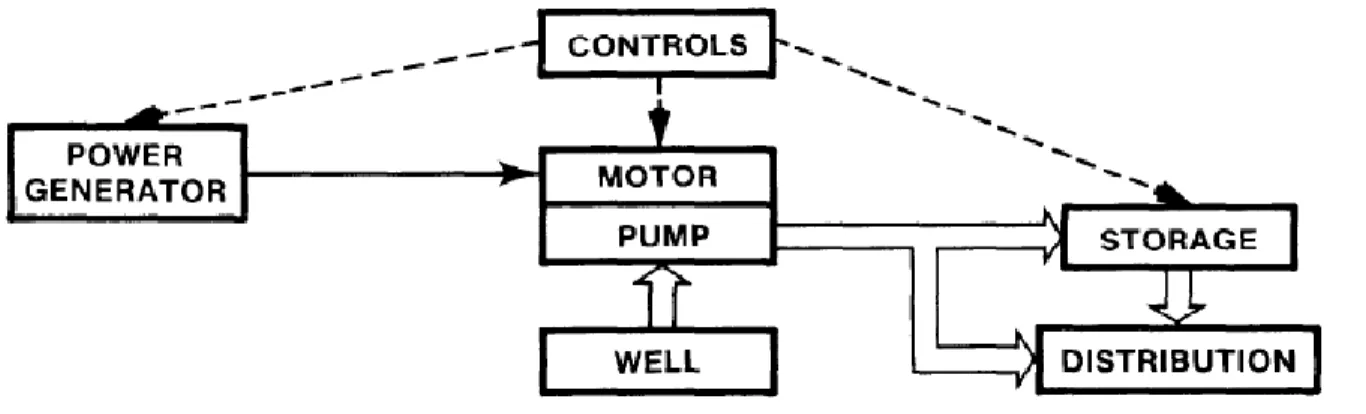
With no moving parts, the PV panel array takes energy from the sunlight and generates DC electricity, which is then directed, through a controller or not, to the pump/motor in what is termed a “direct-coupled” system (Figure 9). The pump/motor combination makes the water move from the source through a pipe to a discharge point, commonly a storage tank. The maximum length of the pipe is determined by the suction capability of the pump [7].
The choice of motor-pump assembly depends on water volume needed, efficiency, price, reliability and availability of support. DC motor are an attractive option because of their compatibility with the power source and because their efficiency is usually higher than AC motors. Also, AC motors require AC to DC inverter. AC motors however have lower price and higher availability[24].
Figure 3 - Block diagram of PV-powered water pumping system (dashed line means optional components)
Electrical controllers and safety devices are incorporated into the system in order to provide electrical protection and switching. Since the amount of power produced depends on solar energy income, the controller can cause the pump to be switched off until sufficient power is available to meet the pump’s minimum operating power. The same function is used to control the power output to the pump to prevent it from running faster than its maximum speed. The pump’s operation can also be controlled by the use of a float switch in the storage tank which responds automatically when a defined water level is reached in the tank [7].
It is possible to use a Maximum Power Point Tracker (MPPT) shows a much favorable figure than direct coupling. This cheap electronic device absorbs the power of the PV array at a fixed voltage and current (for maximum output), and behaves as a current generator for feeding the DC-motor of the pump (for higher pump output). At the input side, the voltage may be chosen close to the maximum power point, and stays quite near for any irradiance. On most commercial DC-DC devices, the input voltage may be adjusted by hardware. At the output side, the power is supposed to be transmitted to the motor at the optimal current/voltage point corresponding to the available power and the motor needs [5].
Storage batteries can be incorporated into the PV pumping system. They can be charged when incoming solar energy exceeds the pumping power requirement. The control unit will regulate battery charge and discharge. However, batteries require a more complex control system and can significantly increase the cost and maintenance of the system. The use of a storage water tank is a more effective and less expensive method of using the surplus of solar energy income.
However, the main disadvantage of the use of batteries or MPPT is the requirement at least one additional electronic component to the systems; hence, they become more expensive, more complicated, and less reliable [1].
To ensure that all the equipment is compatible, it is important that the components are designed as part of an integrated system [7].
In general, the main factors that affect the selection of a solar powered pump/motor are:
Total dynamic head (meters)
The available electric power (peak power) and total energy produced by the PV panel array
The water requirement (in daily cubic meters) [25].
2.5. Pump Sets
The type of pump and mounting can be either submersible, surface mount or floating, depending on the water source.
Regarding maintenance, it is easier to have both motor and pump on surface but this requires to have a large a not deep water source, as one can see on Figure 4. Pump and motor can also be floating on the lake/pond.
If the water source is a deep well, it is better to use a submersible pump with the motor at surface or together with the pump as just one component. A submersible pump is a device where the whole assembly is submerged in the fluid to be pumped[5].
The set represented in Figure 5 is probably the most common configuration. This configuration is easy to install once motor and pump are just one device. Either AC or DC motors can be incorporated into the pump set. If a brushed dc motor is used then the equipment will need to be pulled up from the well (approximately every 2 years) to replace brushes. Brushless dc motors would require electronic commutation.
The versatility of the floating unit set (Figure 6), makes it ideal for irrigation pumping for canals and open wells. The pump set is easily portable and there is a negligible chance of the pump running dry. Most of these types use a single stage submersed centrifugal pump. The most common type utilizes a brushless (electronically commutated) dc motor. Often the solar array support incorporates a handle or 'wheel barrow' type trolley to enable transportation.
The pump set in Figure 7 gives easy access to the motor for brush changing and other maintenance. The low efficiency from power losses and the high cost of installation has been disadvantages. In general this configuration is largely being replaced by the submersible motor and pump set.
Figure 4 - Surface suction pump-set
Figure 5 - Submersible pump and motor
Figure 6 - Floating motor and pump
Figure 7 - Submersible Pump and surface motor
2.6. Market of solar water pumps
The market associated with green energy has increased since the concern with pollution and climate change issues became important worldwide.
Many companies have invested in this new rising market, making prices decrease due to competitiveness between them. From the large number of companies that offer different systems of water solar pumps, several were chosen and are mentioned next:
Lorentz
This company was founded in Germany and offers several products that serve the main application areas. They design, develop and manufacture a wide range of systems using solar pumps. The company also manufactures his own solar panels. There are Lorentz’s projects in different countries like USA and Pakistan.
www.lorentz.de
Agriculturesolar
AgricultureSolar presents several solutions for the agriculture business using solar systems. Besides solar pumping systems, the company also provides lightning products and other for agriculture.
www.agriculturesolar.com
Solar Water Technologies
The solar water pump systems of this company are designed using components from several manufacturers. They have several available systems for different heads and flow pumping. This company is specialized in pv water pump systems for different applications.
www.solarwater.com
Shurflo
This is a north American company that has pumps for several applications, including agriculture. However, they don’t have specific products for water pumping from a well, like a submersible pump. http://www.shurflo.com
Grundfos
Grundfos is an international manufacturer of water pumps for every type of application: domestic buildings, industry, water treatment processes and agriculture. Most of their products for irrigation
3. Design and optimization of a solar water pump system
3.1. Available Solar energy and PV location
Figure 8 - Long-term average solar irradiation (source: http://solargis.info/)
In PV system design it is crucial to make a good analysis of the sunlight available at a particular location at a given time. The two common methods which characterize solar radiation are the solar radiance (or radiation) and solar insolation. The solar radiance is an instantaneous power density in units of kW/m2. It varies throughout the day from 0 kW/m2 at night to a maximum of about 1 kW/m2 and is strongly dependent on location and local weather. Other factors can affect the solar availability such as orientation (tilt and azimuth angle) and the possible shading caused by the surrounding [26]. Solar radiance measurements consist of global and/or direct radiation measurements taken periodically throughout the day. The measurements are taken using either a pyranometer (measuring global radiation) and/or a pyrheliometer (measuring direct radiation). In well established locations, this data has been collected for more than twenty years.
While solar irradiance is most commonly measured, a more common form of radiation data used in system design is the solar insolation. The solar insolation is the total amount of solar energy received at a particular location during a specified time period, often in units of kWh/(m2 day). Solar insolation data is commonly used for simple PV system design[27] .
There are also many meteorological databases, including online databases that have the information about the average solar irradiation for a certain inclination or azimuth angle. One example is the online site of the Photovoltaic Geographical Information System (PVGIS) of the European Institute for Energy and Transport [28].
The available solar energy in a certain location can be also calculated using mathematical models. A model is proposed in Twidell et al [29] for example.
The orientation of the panels is determined by two angles: azimuth (α) and inclination (β). The panels should be oriented towards the terrestrial equator (facing south in the north hemisphere, and north in
the south hemisphere) so that during the day the panels catch the biggest possible amount of radiation. For that reason, α=0 [30]. The inclination angles changes for different applications. For installations with constant or similar consumptions throughout the year, it is better to optimize the installation to capture maximum energy in the winter, so the inclination should be the absolute value of the latitude plus 10º. For installations with inferior consumptions in winter the value of the latitude of the place can be used as the solar panel inclination. For installations that are only used during summer, the value of the inclination should be the latitude angles decreased in 10º [30].
3.2. Water requirement
The first step in the design of a PV water pumping system is to determine the volume of water per day and how far the water is to be transported. It is worth mentioning that predictions of water consumption involve much uncertainty.
Human and animal needs can be estimated by multiplying the daily usage by the population.
It is complicated to determine water needs for humans because water usage varies based on village size, location and lifestyle. For planning the introduction of mechanical pumping systems into a village a daily usage of 40 liters/person/day is suggested. For a larger town, where indoor toilets and showers are more common, a daily usage of 100 liters/person/day is often used [7].
Even more complex, is to estimate the water requirements for irrigation application. In this case, water requirements are depending on the type of soil, how clean is the soil, season and the amount of water that the plants loose through evapotranspiration. The amount of water required to irrigation will be the difference between evapotranspiration and precipitation.
3.3. Water source
The configuration of the water system will be first defined by the type of water source used, as well as by the local topography and the location of the delivery point. The water source could be either subsurface (a well) or surface (a pond). For different water sources, there is a specific type of motor-pumps assembly to use.
In a surface source, the water availability can vary seasonally. For example, the amount and quality of the water can be low during the summer when it is needed the most.
3.4. System layout
There are two basic configurations of PV water pumping systems battery-coupled and direct-coupled. For a particular case of study, several factors must be considered in order to optimize the system.
3.4.1. Direct-coupled system
This is the simplest case. The PV panels are directly connected with the pump, which pumps water through a pipe to where it is needed. Because there is no storage of energy, this system is designed to pump water only during the day and the amount of water pumped is totally dependent on the amount
Figure 9 - direct-coupled system
To have water during the night or on cloudy days, a water tank is attached to the system to store extra water in sunny days. Water-storage capacity is important in this pumping system. Two to five days storage may be required, depending on climate and pattern of water consumption.
3.4.2. Battery-coupled system
Battery banks are often used in PV systems. These banks are set up by connecting individual batteries in series or parallel to get the desired operating voltage or current. The voltage achieved in a series connection is the sum of the voltages of all the batteries, while the current (amps) achieved in series-connected batteries is equal to that of the smallest battery.
The electric current produced by PV panels during daylight hours charges the batteries, and the batteries supply power to the pump anytime water is needed. The use of batteries spreads the pumping over a longer period of time by providing a steady operating voltage to the motor of the pump. Thus, during the night and low light periods, the system can still deliver a constant source of water for livestock.
However, the use of batteries has its drawbacks. First, batteries can reduce the efficiency of the overall system because the operating voltage is dictated by the batteries and not the PV panels. This reduced efficiency can be minimized with the use of an appropriate pump controller that boosts the battery voltage supplied to the pump.
Figure 10 - Battery-coupled system
3.5. Water storage/energy storage
A solar water pumping system does not have to use batteries to provide the power as the pump will operate during the day by pumping water into a tank for use at night.
A water storage tank is normally an essential element in an economically viable solar-powered water pump system. The tank is used to store enough water, during peak energy production, to compensate cloudy weather of maintenance issues with the powered system. It is possible to store the energy as water by pumping it into a tank while the sun is shining and distributing it by gravity when it’s needed after dark. Ideally, the largest tank that can be afforded should be selected. More drawdown means longer pump life and lower power requirement. Two to five days storage may be required, depending on climate and pattern of water consumption. Multiple tanks may be required if the volume of water storage is large [25].
However, the use of water tanks is not the perfect solution. Considerable evaporation losses can occur if the water is stored in open tanks, while closed tanks big enough to store several days water supply can be expensive. Also, water in the storage tank may freeze during cold weather.
Alternatively, energy storage can also be considered by using batteries. This alternative adds cost to the system and its design and maintenance is more difficult.
3.6. Hydraulic energy/total dynamic head for the pump
Figure 11 – Negative Suction Head
Total dynamic head, or sometimes referred to as “Pumping Head”, is the total vertical lift plus head losses due to friction through the pipes.
There are two situations to calculate total dynamic head: with negative and positive suction head. The vertical lift is the vertical distance that the water needs to be pumped, from the location of the pump until the highest point where the water needs to be pumped. In Figure 11(where there’s negative suction head) , the vertical lift is represented by discharge head plus negative suction head. When suction head is positive (Figure 12) vertical lift will be discharged head minus positive suction head.
Figure 12 - Positive Suction Head
VERTICAL LIFT
In a deep well there are some characteristics that need to be taken in account when a pumping system is in operation. The length represented in Figure 13 by B is the static water level, the depth of the water surface in a well under static conditions (when it is not being pumped). It may be subject to seasonal changes or changing after extended pumping. The length represented by C is Drawdown level, the lowering of the level of water in a well due to pumping.
Figure 13 - Well water levels
Head losses still have to be calculated. According to Jenkins [31], the approximate head losses (HL) caused by friction within the pipe is calculated using the Hazen-Williams Empirical formula. The value generated is in units of “feet of head”. Equation (1) illustrates the Hazen-Williams formula:
The roughness coefficient variable C, within the equation depends on the type of pipe, but the roughness coefficient for PVC is typically around 140 [32]. Q is the flow rate in GPM (gallons per minute), D is the nominal inside diameter of the pipe in inches, and L is the total length in feet of the pipe for the system. The final value has to be converted in meters.
The total dynamic head formula is:
(2)
3.7. Types of Pumps and pump selection
One of the major components of these systems is the pump. Conventional pumps use AC current that utility lines or generators supply. Usually, solar pumps use DC current supplied by batteries and/or PV panels. Also, they are designed to work effectively during low-light conditions, at reduced voltage, without stalling (when the pump stops running, typically because of an overload) or overheating. Some solar pumps are fully submersible, while others are not. The use of submersible pumps eliminates potential priming and freezing problems. Most solar water pumps are designed to use solar power most efficiently and operate on 12 to 36 volts DC.
Water pumps can be split into two major categories: centrifugal pumps and positive displacement pumps.
3.7.1. Centrifugal Pumps
Centrifugal pumps basically consist of a stationary pump casing and an impeller mounted on a rotating shaft. The pump casing provides a pressure boundary for the pump and contains channels to properly direct the suction and discharge flow [33]. The pump casing has suction and discharge penetrations for the main flow path of the pump and normally has small drain and vent fittings to remove gases trapped in the pump casing or to drain the pump casing for maintenance.
Figure 14 is a simplified diagram of a typical centrifugal pump that shows the relative locations of the pump suction, impeller, volute, and discharge. The pump casing guides the liquid from the suction connection to the center, or eye, of the impeller. The vanes of the rotating impeller impart a radial and rotary motion to the liquid, forcing it to the outer periphery of the pump casing where it is collected in the outer part of the pump casing called the volute. The volute is a region that expands in cross-sectional area as it wraps around the pump casing. The purpose of the volute is to collect the liquid discharged from the periphery of the impeller at high velocity and gradually cause a reduction in fluid velocity by increasing the flow area. This converts the velocity head to static pressure. The fluid is then discharged from the pump through the discharge connection.
Figure 14 - Centrifugal pump
Some centrifugal pumps contain diffusers. A diffuser is a set of stationary vanes that surround the impeller. The purpose of the diffuser is to increase the efficiency of the centrifugal pump by allowing a more gradual expansion and less turbulent area for the liquid to reduce in velocity. The diffuser vanes are designed in a manner that the liquid exiting the impeller will encounter an ever-increasing flow area as it passes through the diffuser. This increase in flow area causes a reduction in flow velocity, converting kinetic energy into flow pressure.
Centrifugal pump classification by flow
Centrifugal pumps can be classified based on the manner in which fluid flows through the pump. The manner in which fluid flows through the pump is determined by the design of the pump casing and the impeller. The three types of flow through a centrifugal pump are radial flow, axial flow and mixed flow.
Radial flow pumps
In a radial flow pump, the liquid enters at the center of the impeller and is directed out along the impeller blades in a direction at right angles to the pump shaft. An example is shown on Figure 16.
Figure 16 - Radial flow centrifugal pump
Axial Flow Pumps
In an axial flow pump, the impeller pushes the liquid in a direction parallel to the pump shaft. Axial flow pumps are often called propeller pumps because they operate essentially the same as the propeller of a boat. An example is shown on Figure 17
Mixed flow pumps
Mixed flow pumps borrow characteristics from both radial flow and axial flow pumps. As liquid flows through the impeller of a mixed flow pump, the impeller blades push the liquid out away from the pump shaft and to the pump suction at an angle greater than 90º. An example is shown on Figure 18.
Figure 18 - Mixed flow centrifugal pumps
Multi-stage Centrifugal Pumps
A centrifugal pump with a single impeller that can develop high differential pressures between the suction and the discharge is difficult and costly to design and construct. A more economical approach to developing high pressures with a single pump is to include multiple impellers on a common shaft within the same pump casing. Internal channels in the pump casing route the discharge of one impeller to the suction of the next impeller.
Figure 19 shows a diagram of the arrangement of the impellers of a four-stage pump. The water enters the pump from the top left and passes through each of the four impellers in series, going from left to right. The water goes from the volute surrounding the discharge of one impeller to the suction of the next impeller.
A pump stage is defined as that portion of a centrifugal pump consisting of one impeller and its associated components.
Pump characteristic curve
The centrifugal pump characteristic curve is a tool that shows how a pump will perform in terms of head and flow. In centrifugal pumps the delivery head H depends on the f low rate Q. This relationship, also called pump performance, is illustrated by curves.
Figure 20 - Centrifugal pump characteristic curve (example)
For a given centrifugal pump operating at a constant speed, the flow rate through the pump is dependent upon the differential pressure or head developed by the pump. The lower the pump head, the higher the flow rate. After a pump is installed in a system, it is usually tested to ensure that the flow rate and head of the pump are within the required specifications. There are several terms associated with the pump characteristic curve that must be defined. Shutoff head is the maximum head that can be developed by a centrifugal pump operating at a set speed. Pump runout is the maximum flow that can be developed by a centrifugal pump without damaging the pump. Centrifugal pumps must be designed and operated to be protected from the conditions of pump runout or operating at shutoff head.
Centrifugal pump Operation
Improper operation of centrifugal pumps can result in damage to the pump and loss of function of the system that the pump is installed in. It is helpful to know what conditions can lead to pump damage to allow better understanding of pump operating procedures and how the procedures aid the operator in avoiding damage.
Many centrifugal pumps are designed in a way that allows the pump to operate continuously for months or even years. These centrifugal pumps often rely on the liquid that they are pumping to provide cooling and lubrication to the pump bearings and other internal components of the pump. If flow through the pump is stopped while the pump is still operating, the pump will no longer be adequately cooled and the pump can quickly become damaged. Pump damage can also result from pumping a liquid whose temperature is close to saturated conditions.
When the liquid being pumped enters the eye of a centrifugal pump, the decrease in flow area results in an increase in flow velocity accompanied by a decrease in pressure. The greater the pump flow rate, the greater the pressure drop between the pump suction and the eye of the impeller. If the pressure drop is large enough, or if the temperature is high enough, the pressure drop may be sufficient to cause the liquid to flash to vapor when the local pressure falls below the saturation pressure for the fluid being pumped. Any vapor bubbles formed by the pressure drop at the eye of the impeller are swept along the impeller vanes by the flow of the fluid. When the bubbles enter a region where local pressure is greater than saturation pressure farther out the impeller vane, the vapor bubbles abruptly collapse. This process of the formation and subsequent collapse of vapor bubbles in a pump is called cavitation. Cavitation degrades the performance of a pump, resulting in a fluctuating flow rate and discharge pressure. Cavitation can also be destructive to pumps internal components. Cavitation can also cause excessive pump vibration, which could damage pump components.
The condition that must exist to avoid cavitation is that the net positive suction head available (NPSHA) must be greater than or equal to the net positive suction head required (NPSHR).
If a centrifugal pump is cavitating, several changes in the system design or operation may be necessary to increase the NPSHA above the NPSHR and stop the cavitation. One method for increasing the NPSHA is to increase the pressure at the suction of the pump. It is also possible to increase the NPSHA by decreasing the temperature of the liquid being pumped. Decreasing the temperature of the liquid decreases the saturation pressure, causing NPSHA to increase.
If the head losses in the pump suction piping can be reduced, the NPSHA will be increased. Various methods for reducing head losses include increasing the pipe diameter, reducing the number of elbows, valves, and fittings in the pipe, and decreasing the length of the pipe.
It may also be possible to stop cavitation by reducing the NPSHR for the pump. The NPSHR is not a constant for a given pump under all conditions, but depends on certain factors. Typically, the NPSHR of a pump increases significantly as flow rate through the pump increases. Therefore, reducing the flow rate through a pump by throttling a discharge valve decreases NPSHR. NPSHR is also dependent upon pump speed. The faster the impeller of a pump rotates, the greater the NPSHR. Therefore, if the speed of a variable speed centrifugal pump is reduced, the NPSHR of the pump decreases. However, since a pump's flow rate is most often dictated by the needs of the system on which it is connected, only limited adjustments can be made without starting additional parallel pumps, if available.
The net positive suction head required to prevent cavitation is determined through testing by the pump manufacturer and depends upon factors including type of impeller inlet, impeller design, pump flow rate, impeller rotational speed, and the type of liquid being pumped. The manufacturer typically supplies curves of NPSHR as a function of pump flow rate for a particular liquid (usually water) in the
3.7.2. Positive displacement pumps
Positive displacement pumps operate on a different principle than centrifugal pumps. Positive displacement pumps physically entrap a quantity of liquid at the suction of the pump and push that quantity out the discharge of pump.
According to [33],a positive displacement pump is one in which a definite volume of liquid is delivered for each cycle of pump operation. This volume is constant regardless of the resistance to flow offered by the system the pump is in, provided the capacity of the power unit driving the pump or pump component strength limits are not exceeded. The positive displacement pump differs from centrifugal pumps, which deliver a continuous flow for any given pump speed and discharge resistance.
Positive displacement pumps can be grouped into three basic categories based on their design and operation. The three groups are reciprocating pumps, rotary pumps, and diaphragm pumps.
All positive displacement pumps operate on the same basic principle. This principle can be most easily demonstrated by considering a reciprocating positive displacement pump consisting of a single reciprocating piston in a cylinder with a single suction port and a single discharge port as shown in Figure 21. Check valves in the suction and discharge ports allow flow in only one direction.
Figure 21 - Reciprocating Positive Displacement Pump Operation
During the suction stroke, the piston moves to the left, causing the check valve in the suction line between the reservoir and the pump cylinder to open and admit water from the reservoir.
During the discharge stroke, the piston moves to the right, seating the check valve in the suction line and opening the check valve in the discharge line. The volume of liquid moved by the pump in one cycle (one suction stroke and one discharge stroke) is equal to the change in the liquid volume of the cylinder as the piston moves from its farthest left position to its farthest right position.
Reciprocating pumps
As it was said before, reciprocating pump are the simplest type of positive displacement pumps. They work using a piston that moves to the right and to the left, moving the liquid from the suction to the discharge in one cycle.
In general, the effective flow rate of reciprocating pumps decreases as the viscosity of the fluid being pumped increases because the speed of the pump must be reduced.
Rotary Pumps
Rotary pumps operate on the principle that a rotating vane, screw, or gear traps the liquid in the suction side of the pump casing and forces it to the discharge side of the casing. These pumps are essentially self-priming due to their capability of removing air from suction lines and producing a high suction lift. In pumps designed for systems requiring high suction lift and selfpriming features, it is essential that all clearances between rotating parts, and between rotating and stationary parts, be kept to a minimum in order to reduce slippage. Slippageis leakage of fluid from the discharge of the pump back to its suction.
Figure 22 - Simple Gear Rotary Pump
Due to the close clearances in rotary pumps, it is necessary to operate these pumps at relatively low speed in order to secure reliable operation and maintain pump capacity over an extended period of time. Otherwise, the erosive action due to the high velocities of the liquid passing through the narrow clearance spaces would soon cause excessive wear and increased clearances, resulting in slippage.
Diaphragm pumps
Diaphragm pumps are also classified as positive displacement pumps because the diaphragm acts as a limited displacement piston. The pump will function when a diaphragm is forced into reciprocating motion by mechanical linkage, compressed air, or fluid from a pulsating, external source. The pump construction eliminates any contact between the liquid being pumped and the source of energy. This eliminates the possibility of leakage, which is important when handling toxic or very expensive
Figure 23 - Diaphragm Pump
Positive Displacement Pump Characteristic Curve
Positive displacement pumps deliver a definite volume of liquid for each cycle of pump operation. Therefore, the only factor that affects flow rate in an ideal positive displacement pump is the speed at which it operates. The dashed line in Figure 24 shows actual positive displacement pump performance. This line reflects the fact that as the discharge pressure of the pump increases, some amount of liquid will leak from the discharge of the pump back to the pump suction, reducing the effective flow rate of the pump (slippage).
Figure 24 - Positive Displacement Curve Characteristic Curve – Example
Positive displacement pumps are normally fitted with relief valves on the upstream side of their discharge valves to protect the pump and its discharge piping from overpressurization. Positive displacement pumps will discharge at the pressure required by the system they are supplying. The relief valve prevents system and pump damage if the pump discharge valve is shut during pump operation or if any other occurrence such as a clogged strainer blocks system flow.
How to select – Centrifugal Pumps vs Positive Displacement
To choose between a centrifugal and a positive displacement pump is not always a clear decision. By looking at the performance chart below one can see just how different they are. The centrifugal has varying flow depending on pressure or head, whereas the PD pump has more or less constant flow regardless of pressure.
Table 3 - Summary table for chosen pump
Situation Best Pump
Constant Flow at various pressures Positive Displacement Constant Flow at various viscosities Positive Displacement
Constant flow at high viscosities Positive Displacement Constant Pressure and constant flow rate Centrifugal
High flow / low head Centrifugal
Low flow / high head Positive Displacement
In conclusion, it is possible to say that the efficiency of positive displacement pumps are higher compared to centrifugal pumps. In Hamidat et al. [35] two mathematical models are presented to simulate the long-term electric and hydraulic performance of both types of pumps. The performance was calculated using the measured meteorological data of different sites located in Sahara and the coastline regions of Algeria. It has been reported that the average pumping head and total efficiencies of the positive displacement pumps are higher for a large range of the total head compared to the centrifugal pumps. The average losses of the positive displacement are lower than the centrifugal pumps, especially for high total heads. The average volume of water pumped by positive displacement pumps is higher compared to that of the centrifugal pumps.
3.8. Types of motors
As well as there being several types of pump available, there are also several types of motor, including DC and AC, brushed and brushless, permanent magnet and variable reluctance, synchronous and asynchronous, and so on. Again, each of them has different characteristics. The selection of the motor is dependent on the size, the efficiency requirements, the price, the reliability and the availability. DC motors are attractive because they can directly connect to the photovoltaic array. DC motors are not suitable for high power (above 7kW) applications [4], where an AC induction motor with a DC-AC inverter is required. The use of an inverter will lead to additional costs and energy losses. For submersible DC water pumps, maintaining and replacing the brushes of the DC motors requires the pump to be removed from the deep well, which increases the running and maintenance costs and also reduces its reliability and life.
Brushless DC motors were made to overcome these drawbacks. The brushless DC motors were used for SPWPSs using helical pumps, and their performance was tested in Australia. It was reported that the efficiency of the system using brushless DC motors varies between 30% and 50%, which is reported to be better than conventional SPWPs.
In a similar investigation, Metwally et al. tested a switched reluctance motor (SRM). The motor is supplied by a DC current through a switching circuit. The efficiency of the SRMs was reported to be higher than the efficiency of regular DC or AC motors. Also, SRM are cheaper than DC and AC motors. In another situation, Singh et al. developed a permanent magnet brushless DC motor drive powered by a solar photovoltaic array coupled with SPWPSs. The developed prototype operates satisfactorily with different DC voltages. The system was found to be suitable to pump water even during lean sunshine hours.
On the sizing study ahead, brushless DC motor was chosen. The main advantage of these motors lies in the absence of rotating contacts such as several kinds of brushes. The lack of brushes eliminates the periodic inspection and maintenance required for brush-type motors. This kind of motors are used in industries such as Appliances, Automotive, Aerospace, Consumer, Medical, Industrial Automation Equipment and Instrumentation.
BLDC motors have many advantages over brushed DC motors and induction motors. A few of these are:
• Better speed versus torque characteristics • High dynamic response
• High efficiency • Long operating life • Noiseless operation • Higher speed ranges
In addition, the ratio of torque delivered to the size of the motor is higher, making it useful in applications where space and weight are critical factors.
![Table 1 - Summary of principal advantages and disadvantages for diesel, wind and solar- solar-powered pumps [7]](https://thumb-eu.123doks.com/thumbv2/123dok_br/15257025.1024973/12.893.96.791.151.633/table-summary-principal-advantages-disadvantages-diesel-solar-powered.webp)