DOI: ISSN: 2318-4531 Abstract — Mineral processing facilities usually have storage
bins for transitory housing of the ore supplied to their processing lines. Facilities with large rectangular bins often have a tripper car to spread the ore along the entire extension of the bin, by means of forth and back traveling movements. The positioning control of a tripper is a relevant, yet less concerned, control problem, with significant impact on the productivity of mineral processing facilities, since a badly controlled tripper may be a true source of bottleneck. This work concerns the development and implementation of a strategy for autonomous positioning of a tripper in a large iron ore processing facility, with the goal of eliminating the need for a local operator to decide the tripper positioning under manual operation. Such “autonomous positioning advisor” acts as an expert system to determine the “best” position (bin cell) where the tripper should be placed to feed the bin, in order to meet some operational requirements as: (1) to better uniformize the ore level across the entire bin; (2) to prevent excessive and unnecessary travels of the tripper; and (3) to suppress the ore discharge from the tripper to the bin when the tripper needs to travel over fully filled cells to reach the destination cell. The positioning control strategy was based on operational knowledge and procedures used by the tripper operators when operating the tripper in manual mode. The results obtained with the autonomous positioning advisor allowed the tripper to operate consistently in automatic mode and led to improved operational performance.
Index Terms — autonomous machines, expert systems, industrial automation, mineral processing, process control, sequential control, tripper.
I. INTRODUCTION
HE Carajás Iron Ore Processing Plant I, from VALE, is the biggest mineral processing plant in the world. It produces high-grade iron ore in the forms of pebble, sinter-feed, and pellet-feed, mostly destined to exportation. The plant has a current production capacity of 100 MTPY (million tonnes per year). In 2015, the total production accomplished by the plant
was about 128 MTPY, and its major overseas customers were: China (62.4%), Japan (8,8%), Germany (5.9%), South Korea (4.3%), and France (2.6%). Since the past decade, better practices of industrial operation, maintenance and automation have been implemented in the plant, to sustain and improve its performance towards higher production goals. The Automation Department has been responsible for the design and implementation of process control and automation initiatives to increase productivity and reduce wastefulness, to improve the operational efficiency of the plant.
Mineral processing plants comprise several facilities to perform processing stages such as: crushing, screening, milling, hydrocycloning, and filtration, among others. Storage bins are a basic component of some facilities. They intend to temporarily store the bulk ore before it is sent to the mineral processing lines, as well as to act as “material backup” structures, preventing the production of its facility from ceasing due to production stoppages in the upstream facility which supplies ore to the bin. Usually, those bins are large structures with a tripper machine at its top, to spread the ore inside along the bin.
II. ORE STORAGE PROCESS
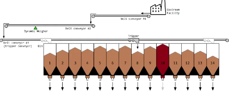
The Secondary Screening facility [1,2] is the major processing unit of the Carajás Iron Ore Processing Plant. It has a large storage bin with 14 cells, each of which feeds a specific processing line, as shown in Fig. 1. At the top of the bin, there is a tripper, which receives ore through a belt conveyor circuit from the upstream facility. The tripper can travel forward or backward along the entire extension of the bin, to spread the ore inside along the bin. The input mass flowrate (in t/h) of ore fed by the tripper to the bin is measured by a dynamic weigher (belt scale) [7] assembled on an upstream belt conveyor. The feeders located at the bottom side of the bin work reclaiming and discharging the ore in the downstream processing lines.
Sidney A. A. Viana
____________________________________________________________________________
Autonomous Positioning Advisor for Trippers in
Mineral Processing Facilities
T
______________________________________________________________ Sidney A. A. Viana is a Senior Member of the IEEE – The Institute of Electrical and Electronics Engineers (USA). He is currently with VALE’s Centre of Excellence, Nova Lima, MG, Brazil. (e-mail: [email protected]).
DOI: ISSN: 2318-4531 Each feeder at the bottom of the bin cells is driven by an
induction motor powered by a variable frequency driver (VFD) [11], which allows to change the feeder speed and hence the feeding flowrate for the processing line. By design, the maximum feeding flowrate of each feeder is about 1300 t/h. Therefore, the facility can attain a maximum processing flowrate of about 14 × 1300 = 18200 t/h of ore. The tripper spreads the feeding ore into the bin by means of forth and back positioning movements controlled by the SCADA plant control system under two operating modes: manual or automatic.
In manual mode, the tripper position control is performed by a local operator using a lever, from the tripper operation cabin, as shown in Fig. 3. With the lever at its unstrained position, the tripper stands at its current position, with translation motors stopped and translation brakes [12] locked. When the lever is strained, either forward or backward, the translation brakes are released and the translation motors are driven by the variable frequency driver (VFD) [11], according
to the direction the lever is strained. The operator decides the tripper positioning with the support of a human-machine interface (HMI) [14] at the cabin, which shows all relevant operational variables related to the ore storage process, specially the feeding flowrate to the tripper, the level of ore in each cell of the bin, and the current position of the tripper. The movement commands provided by the operator using the lever are sent to a dedicated programmable logic controller (PLC) [13] responsible for the machine-level control of the tripper.
In automatic mode, the tripper positioning is performed exclusively by the PLC, based on the same relevant variables of the storage process (tripper position, level of ore in the cells of the bin, feeding flowrate to the bin). However, the decisions about the next cells to be filled by the tripper must also be defined autonomously, not by a local operator. Therefore, the basis for the tripper operation in automatic mode is a computational strategy to set reliable autonomous decisions on the tripper positioning.
Fig. 1. Layout of the storage process for the Secondary Screening facility of the Carajás Iron Ore Processing Plant I.
Fig. 2. Tripper of the Secondary Screening facility of the Carajás Iron Ore Processing Plant.
Fig. 3. Operation cabin of the tripper, with a local operator controlling the machine position in manual mode.
DOI: ISSN: 2318-4531 III. THE TRIPPER POSITIONING PROBLEM
The positioning control of a tripper must consider the operational conditions of the storage process (feeding flowrate, material level in the bin, tripper position, etc), the required performance (uniformization of material level in the bin, avoiding frequent direction reversals in tripper traveling, etc), and the available implementation resources (field instruments and actuators, PLC capabilities, etc).
All the machine-level control of the tripper was performed by a dedicated PLC, and implemented using ladder language [13]. The original positioning control strategy to operate the tripper in automatic mode was very ineffective because only the material levels of the bin cells were considered to define the further positions of the tripper. The tripper was always moved to the cell having the lowest material level, with no concerns to other relevant operational variables. As an example, suppose the tripper had been filling the 4th cell of the bin and the two
cells with lowest ore levels were the 7th (with a level of 45%)
and the 12th (with a level of 43%). The original positioning
control would move the tripper from the 4th cell directly towards
the 12th cell (passing across the 7th cell), only because this last
cell has the lowest level of ore, although the level of the closer 7th cell was just a tiny higher. After the tripper had filled the 12th
cell, it would then be moved back towards the 7th cell, supposing
no other cell had gotten the lowest level. Clearly, this filling sequence has excessive excursions and unnecessary traveling reversals of the tripper to spread the ore into the bin. A more efficient way to perform this operation would be to move the tripper from the 4th cell to the 7th cell, fill this one, and then
move the tripper forward to the 12th cell, thus performing a
shorter excursion with no traveling reversal to fill both those cells. Avoiding excessive excursions and unnecessary traveling reversals of the tripper is extremely important to prevent premature deterioration of its translation system, with the associated maintenance downtimes and costs.
Furthermore, in the event of stoppage of a production line and the corresponding feeder at the bottom of the bin, the level
conveyor belts, and the upstream facility, with consequent loss of production. To prevent such abnormal situation, a temporary suppression of ore feeding to the tripper should be done at the upstream facility, synchronized with the travel of the tripper over the stopped cell(s) of the bin. In the Secondary Screening facility, the production lines downstream the feeders at the bottom of the bin have several processing equipments with only reasonable operational reliability, resulting in a good chance that a line stops by equipment failures, leading the material level in its corresponding bin cell to gradually increase, until preventing the tripper to travel over the cell.
For years, the operational constraints described above had been the major difficulties to operate the tripper in automatic mode by the original positioning strategy. Consequently, the tripper had been operated almost always in manual mode by a local operator. The tripper was rarely left operating in automatic mode, except in unusual soft operating conditions of low average level of ore in the bin, and low feeding flowrate. Therefore, it was necessary to develop a new strategy for tripper positioning, to allow its full autonomous operation.
IV. STRATEGY FOR AUTONOMOUS TRIPPER POSITIONING The development of a new strategy for autonomous positioning of the tripper started with a set of meetings involving people from the Automation and Operation departments, specially the tripper operators. The purpose of those meetings was to discuss what should be a better and efficient way to operate the tripper in automatic mode, what performance requirements should be achieved, and what were the major operational constraints to deal with.
The overall performance requirement was defined as “fill the bin in such way to make the material level more uniform across the cells, prevent excessive excursions of the tripper, and perform synchronized feed cuttings when the tripper needs to travel over a fully filled cell”. By attending this requirement, it was expected to drastically reduce – and perhaps eliminate – the need for manual control of the tripper by a local operator.
The overall requirement was divided into three operational requirements: positioning of the tripper, filling of the bin, and feed cuttings, described in the following. All these requirements were modelled using simple mathematical formulations, so that they could be easily implemented in ladder language, to run in the native PLC of the tripper.
A. Positioning of the tripper
The decision on the tripper positioning is the choice of the “best cell to be filled” by the tripper after it finishes filling the current cell. This choice can be done in many ways, according to the needs of the process. In this work, the choice of the “best cell to be filled” was based on the requirement for uniformization of material level in the bin. Based on practical Material Level
(cm)
14 Ultrasonic Level Sensors
Assembled at the top of each cell of the bin.
Tripper Position, continuous (cm)
1 Absolute Encoder
Assembled to a specific wheel of the tripper. Tripper Position, discrete (cm) 4 Magnetic Proximity Switches Assembled at 4 equally spaced positions along the bin extension, to provide position resetting. Tripper Translation
Speed (cm/s)
1 Variable Frequency Driver
Installed at the power house of the tripper. It drives all the 4 translation motors. Tripper Translation
Lock (on/off)
6 Electromagnetic Disc Brakes
Assembled to each tripper wheel.
DOI: ISSN: 2318-4531 knowledge provided by the tripper operators, the choice of the
“best cell” was defined as a balance between the level of ore in the cell and its distance to the current position of the tripper. The following process variables were considered to define the “best cell”:
1) Level of ore in the bin cells
Each cell of the bin had an ultrasonic level sensor to measure the degree of filling (level of ore) of the cell, in a percent scale ranging from 0% to 100%, where 0% means an empty cell, and 100% means a fully filled cell. Those level measurements were used to prioritize the filling of cells with lower levels of ore. Denoting the number of cells in the bin by NC = 14, for a given cell j with level Lj, where 1 ≤ j ≤ NC and 0 ≤ Lj ≤ 100, the Priority for Positioning by Level, PLj, for each cell j was defined as:
100 100 j L j L PL (1)
where L is a scale factor. Since Lj varies between 0 and 100, PLj will vary between 0 and L. For convenience, the scale factor was chosen as L = 5000. Equation (1) means
that the emptier a cell is, the higher is its priority index PLj. Fig. 4 shows that PLj is a linear function of the continuous variable Lj. As an example, suppose that at a certain moment the level of ore into the 7th cell of the bin is 89% (L7 = 89),
and the level of the 11th is 61% (L
11 = 61). Then, the Priority
for Positioning by Level for these cells will be: PL7 =
5000(100–89)/100 = 550, and PL11 = 5000(100–61)/100 =
1950. Since PL11 > PL7, the 11th cell has more priority to be
filled than the 7th cell. By calculating PL
j for the all cells of the bin, it’s possible to prioritize their filling according to their level, just as the tripper operators do when controlling it in manual mode. In other words, equation (1) is a way to represent the operational knowledge of the tripper operators about how to prioritize the bin cells to be filled according to their level of ore.
2) Relative distance between the tripper and the cells The tripper position is measured by an absolute encoder installed in one of the tripper wheels (see Table I). Since the minimum and the maximum curse positions for the tripper
along the bin extension are known, the relative distance between the tripper and the cells of the bin can be computed from the measured position of the tripper, provided by the encoder. Those distances were used to prioritize the further positioning of the tripper at closer cells, relatively to the cell that the tripper is currently filling. This rule intends to prevent excessive excursions of the tripper. Denoting by p the current cell on which the tripper is (1 ≤ p ≤ NC), the
Priority for Positioning by Distance, PDj, for each other cell j≠p was defined as:
14 ; ; 1 1 C C D j j p N N p j PD (2)
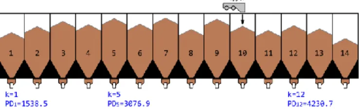
where D = 5416.67 is a scale factor to adjust PDj to the same range of PLj in (1). Since the tripper can be at either a forward (p > k) or a backward (p < k) position relatively to a possible next cell j to which it could be moved to, only the absolute distance |k – p| matters. Fig. 5 shows that PDj is a linear function of the discrete variables j and p. As an example, Fig. 5 illustrates the value of the priority index PDj for the 1st, 5th, and 12th cell of the bin (j = 1, 5, 12) when the
tripper is currently filling the 10th cell (p = 10). Clearly, PD
j acts to prioritize the positioning of the tripper at closer cells to the tripper. By calculating PDj for the all cells of the bin, it’s possible to prioritize their filling according to their relative distance to the tripper, just as the tripper operators do when controlling it in manual mode.
3) Free regions within the bin
It is very common for a production line to stop operating due to unexpected equipment failures, as well as being intentionally put out of operation for maintenance. The bin cell of a stopped line is referred as a “stopped cell”. The
Fig. 4. Priority index PLj × level Lj.
Fig. 5. Priority index PDj × absolute distance |j – p|.
DOI: ISSN: 2318-4531 eventually reaching a maximum safe level limit LS. If this
limit is reached, the cell is regarded as a “blocked cell”, a safety protection interlock is activated by the PLC, and the tripper is no more allowed to transit over the blocked cell, unless its material flowrate provided by the upstream facility is ceased.
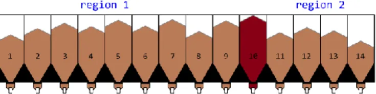
Fig. 7 and Fig. 8 shows two common occurrences of blocked cells. In Fig. 7, the 10th cell is blocked, creating two
“free regions” for the tripper operation within the bin. Different combinations of blocked cells generate different occurrences of free regions within the bin. The largest free region possible is obviously the entire bin with no blocked cells. When a cell is blocked, the tripper excursions become restricted to the free region where the tripper is. Consequently, the cells in other(s) region(s) of the bin become empty faster, since they are not attended by the tripper. Fig. 8 illustrates an additional example where two adjacent cells are blocked, creating a very short region with only three valid cells (12, 13, and 14) which tends to empty faster than the larger region. Clearly, the effect of blocked cell(s) is to restrict the extension of the bin along with the tripper can operate, leading to a faster filling of the region on which the tripper is confined, at the risk of an overload, and causing a lack of ore in the other region(s) no more fed with ore by the tripper, leading to losses of productivity of their corresponding production lines.
From practical knowledge on the manual operation of the tripper, in the event of a stopped but not yet blocked cell, the tripper should operate, by default, in the largest free region of the bin, to reduce the need to transit over the stopped cell. The tripper should move to a smaller free region when the level of ore in its cells become so much low. In other words, the tripper must operate primarily on the largest free region, and any decision to move the tripper to shorter free regions with low level of ore can be conveniently driven by the
discharging ore into it. Otherwise, the level of ore in the stopped cell will quickly increase as the tripper transits over it. The feed cutting must last be synchronized with the transit of the tripper over the blocked cell. The feed cutting duration can be easily calculated from cell width and the fixed translational speed of the tripper.
In order to establish operational safety references for cell filling, the following level limits were defined:
Critical Level: LC = 100 % Safe Level: LS = 95 % High Level: LS ≤ Lj ≤ LC
where LC is the maximum physical level; LS is the maximum safe level for normal operation; and the High Level condition for Lj is simply a warning level range. Any cell with level Lj in the High Level condition is regarded as “blocked cell”.
For a cell j laying in a free region comprising NF cells, the
Priority for Free Region PRj was defined as:
1 1 C F R N j N N PR F (3)
where R = 5000 is a scale factor to adjust PRj to the same range of PLj in (1) and PDj in (2), and NF is the length (number of cells) of the region containing the cell j. Notice that all the cells in the same region will have identical values for PRj. As an example, the two regions in Fig. 7 have NF = N1 = 9 (region 1)
and NF = N2 = 4 (region 2). Any cell in the first region (j=1, …,
9) has PRN1j = R(N1–1)/(NC–1) = 5000(9–1)/(14–1) = 3076.92. Similarly, any cell in the second region (j=11, …, 14) has PRN2j = R(N2–1)/(NC–1) = 5000(4–1)/(14–1) = 1153.85. Since PRN1j > PRN2
j, the first region has more priority to be filled than the second region, just as the tripper operators do when controlling it in manual mode.
Fig. 7. Example of free regions delimited by one blocked cell.
DOI: ISSN: 2318-4531 4) Operational Utilization
Depending on the production plan of the Carajás Iron Ore Plant, there are situations when some production lines of the Secondary Screening facility should be operated (utilized) at either a higher or lower production rate with regards to other lines. To meet this requirement, three levels of operational utilization (U) for the production lines were defined: 1 (low), 2 (normal), and 3 (high). The higher the utilization of a line, the higher its production flowrate. Since each production line corresponds to a specific bin cell, the
Priority for Filling by Operational Utilization, PUj, for each cell j was defined as:
1
; {1 ,2 ,3} U j j
j U U
PU
(4)where U = 2500 is a scale factor to adjust PUj to the same range of PLj in (1), PDj in (2), and PRj in (3).
Equations (1) to (4) define priorities for the tripper positioning regarding to specific operational aspects. Since all those aspects need to be considered together in the positioning of the tripper, the overall Positioning Priority, PPj, for each cell j was defined as a weighted average of all its specific priorities: 4 3 2 1 4 3 2 1 w w w w PU w PR w PD w PL w PP j j j j j (5)
where the parameters wi are weighting factors to define the relative importance for material level, distance to the tripper, free region, and line utilization on the tripper positioning. Since all the priorities PLj, PDj, PRj, and PUj, have exactly the same range due to their specific scale factors, the weighting factors in (5) can be chosen between 0 and 1, so that:
1
0
w
i
(6)1
wi (7)When the tripper is filling a specific cell of the bin, the values of PPj for all the valid (not stopped and not blocked) cells are computed. The cell j* with the highest priority PPj is
the one to which the tripper must go after finishing to fill the current cell, that is:
PPjj* arg.max (8)
Notice that when the tripper remains filling a specific cell, the priorities for distance (PDj), free region (PRj), and utilization (PUj) usually do not change, but the priority for level (PLj) changes continuously due to the reclaiming of ore by the feeders at the bottom of each cell.
The Positioning Priority in (5) is an efficient yet simple quantitative representation of the heuristic decisions on tripper positioning performed by the operators during manual control of the tripper, and allows a great flexibility to adjust the relative importance of the operational aspects (level, distance, region, and utilization) which are relevant for the tripper positioning. Notice that new aspects can be easily taken into account in the tripper positioning, by simply defining a new specific priority and then including it in the overall Positioning Priority (5).
B. Filling of the Bin
When the tripper reaches a cell to be filled, defined previously by the Positioning Priority in (5), the next decision is “how much should the cell be filled?”. Since the goal is to fill the bin uniformly, and considering that the tripper transits less often over the cells located at the extreme sides of the bin, a set of reference levels Lrj for each cell j of the bin were defined so that Lrj is higher for cells located at the extreme sides of the bin, as shown in Table II and Fig. 11. When the actual level of ore Lj in the cell j currently being filled by the tripper reaches its respective reference level (Lj = Lrj), the tripper starts traveling to the next cell to be filled, j*, according (8). The reference levels Lmj chosen for the cells are shown in Table II and Fig. 11.
Notice that the expected time duration for which the tripper remains positioned over a cell j to fill it is the time to reach its respective reference level Lmj. This time depends on the initial level in the cell and on the difference between the input ore flowrate supplied by the tripper to the cell and the output ore flowrate reclaimed by the feeder from the cell. Therefore, the tripper will usually last longer times filling cells with low initial levels, low feeder flowrates, and higher reference levels Lmj, just as the tripper operators do when controlling it in manual mode.
C. Feed Cuttings
Recall from Fig.1 that the feeding ore supplied by the tripper to the bin of the Secondary Screening facility is produced by the upstream facility. As explained early, it is necessary to suppress or “cut” the feeding when the tripper needs to travel over a blocked cell, so that it can safely move from its current free region to another free region, as illustrated in Fig. 7 and Fig. 8. The control program in the PLC must check continuously if the tripper will need to travel over a blocked cell, in order to suppress temporarily the output flowrate of the upstream facility that feeds ore to the tripper. By knowing the travel time Fig. 10. Priority index PUj × utilization Uj.
DOI: ISSN: 2318-4531 of the ore from the upstream facility to the position of the
blocked cell in the bin of the Secondary Screening facility, the starting and ending time of the feed cutting can be synchronized with the traveling duration of the tripper over the blocked cell. Since the transportation speed of the conveyor belts and the translation speed of the tripper are fixed, the implementation of synchronized feed cuttings depends only on the travel time of the ore from the upstream facility to the blocked cell in the Secondary Screening facility.
V. IMPLEMENTATION OF THE AUTONOMOUS POSITIONING STRATEGY
The tripper positioning strategy described in Section IV was implemented with the existing control system infrastructure of the tripper. The only necessary investment was to contract system integration services to write, test, deploy, and tune the new ladder program for autonomous operation of the tripper, according to the strategy developed by VALE and hereby presented. The implementation resulted in a truly PLC-based expert system for tripper positioning.
There was also necessary to implement some safety interlocks for proper protection of the equipments against the possible occurrence of known unsafe operational conditions. However, the description of those aspects is beyond the scope of this article.
A. Hardware and Software Aspects
The autonomous positioning strategy for the tripper was implemented in ladder language using the software RS-LogixTM
Software RS-ViewTM 32 supervision software, for use at the
Plant Control Room.
The supervisory interface is shown in Figure 12. The 5th and
12th cells of the bin were blocked, resulting in three regions in
the bin for tripper operation. The light brown bars indicate the actual level of ore into the cells, measured by their respective ultrasonic level sensors. The narrow blue bars indicate the reference levels Lmj of the cells (compare with Fig. 11). The position of the tripper in the interface is updated according to its actual position signal provided by the tripper translation encoder. The tripper had just finished to fill the 10th cell (its
level reached the corresponding reference level) and was traveling to the 11th cell (the next “best cell” to be filled). The
5×14 numeric frame at the bottom of the interface shows the values for all the priority indexes computed by the positioning system, so that the operators could assess the system performance. All variable values in the interface are updated in real time, allowing a full supervision of the autonomous positioning system.
B. Human Aspects
In the early stages of the project, many multidisciplinary meetings were done with people from the Automation and Operation departments, to clearly understand the conditions and constraints for autonomous operation of the tripper, as well as to define suitable performance requirements. After the implementation of the autonomous positioning strategy, new meetings were done to present the strategy for the operators, and to assess the achieved performance of the system, so that it could be continually tuned and refined, with the goal to discontinue the manual operation of the tripper.
VI. RESULTS
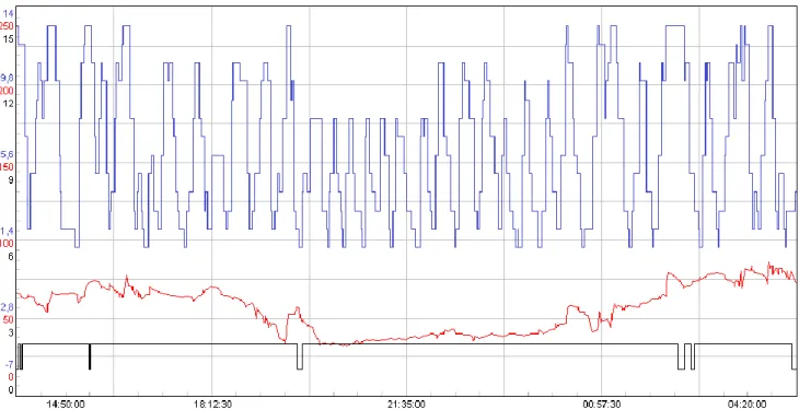
The tripper performance under operation in automatic mode by the autonomous positioning system is shown in Fig. 13. The black line is the operating mode of the tripper (0 = Manual, 1 = Automatic); the red curve is the average level of ore in the bin (the mean value of ore level for all bin cells); and the blue line indicates the cell over which the tripper was along the time. In other words, the blue line shows the excursions of the tripper over the bin. From the time axis, the tripper operated in automatic mode for over 13.5 hours, with a few short periods in manual mode to overcome some constrained operational conditions. This was an unprecedent performance result provided by the autonomous positioning system. Notice that when the average level of ore in the bin was low (for instance, bellow 50%), the tripper operated, as expected, mostly in the central part of the bin and with shorter excursions, as indicated by the green rectangle in the figure, since the Priority for Positioning by Distance (2) prevented excessive excursions. On the other hand, when the average level of ore in the bin was high Fig. 11. Reference levels for filling the bin cells, according to Table II.
4 55 5 50 6 48 7 45 8 48 9 50 10 55 11 60 12 65 13 75 14 80
DOI: ISSN: 2318-4531 (for instance, above 50%), the tripper operated with longer
excursions, as expected, since the Priority for Positioning by Distance (2) turned less significant
The weighting factors wi in equations (5), (6), and (7) were initially chosen all equal to 0.25. Besides the result example shown in Fig. 13, further performance assessments indicate that the tipper would perform really well under autonomous
operation when the average level of the bin would be below 80% and there would be few blocked cells. As the average level in the bin and/or the number of blocked cells increase, the tripper performance became more constrained, turning its autonomous operation more difficult, yet not impossible. Only in such cases, a local operator would be assigned to control the tripper locally in manual mode.
Fig. 12. Supervisory screen of the autonomous positioning system.
DOI: ISSN: 2318-4531 cells and the relative distance of the tripper to the cells. Other
variables, like the existence of free regions in the bin, and the operational utilization were considered to improve the autonomous positioning decisions.
This work can be used as a guideline for the development of similar applications in other mineral processing plants. However, for potential new applications, a preliminary assessment of the operational conditions of the storage process and the machines involved must be performed to identify the relevant variables to be considered.
The positioning strategy developed in this work used priority rules based on simple algebraic equations to represent the relevant operational aspects for positioning of the tripper. The major motivation for the use of simple algebraic rules was the need to implement the strategy in a SCADA control system, resulting in a PLC-based expert system.
As a suggestion for further works, an optimization method may be used to compute the weighting factors wi in equation (5). In this work, those weights were all set to a fixed value chosen from practical and something subjective knowledge about the storage process and the tripper operation. A better way to obtain those weights would be using an optimization method that minimizes a given cost function related to the performance of the storage process. This will require the prior development of a mathematical model of the storage process and the tripper positioning, to be used by the optimization method. An optimization method could also be used to determine best values for the reference levels Lmj shown in Table II and Fig. 11.
Another suggestion for further works, is the use of fuzzy rules to model the priority indexes (1), (2), (3), (4), and maybe (5). This will result in a “fuzzy expert system” for tripper positioning. However, such system cannot be implemented in a PLC, and will require additional industrial hardware to implement fuzzy computations, and with the ability to communicate with the native control system of the plant.
ACKNOWLEDGMENT
The author would like to thank the Automation Department of the Carajás Iron Ore Processing Plant for the support to this project. He also thankfully acknowledges all Tripper Operators and Control Room Operators involved in the project, for their valuable discussions about the technical requirements for the autonomous positioning system, as well as for their support during the deployment of the system.
[3] VALE – Projeto Ferro Carajás, “Repotenciamento 70 MTPA, Tripper TR-131K-01: Folha de Dados, DF-131K-42-3262-0004 Revisão 1”, VALE, Parauapebas, PA, Brasil, 2004.
[4] VALE – Projeto Ferro Carajás, “Repotenciamento 70 MTPA, Tripper TR-131K-01: Conjunto, 131K-02-3271 Revisão 5”, VALE, Parauapebas, PA, Brasil, 2003.
[5] VALE – Projeto Ferro Carajás, “Repotenciamento 70 MTPA, Tripper TR-131K-01: Arranjo Geral, DF-131K-02-3262-0100 Revisão 3”, VALE, Parauapebas, PA, Brasil, 2004.
[6] VALE – Projeto Ferro Carajás, “Repotenciamento 52 MTPA, TR-131K-01 Tripper: Acionamento – Conjunto, 131K-42-9417 Revisão 1”, VALE, Parauapebas, PA, Brasil, 1998.
[7] SCHENCK Process. “MULTIBELT Multi-Idler Belt Weighers”. Brochure BV-D2050GB.
[8] MILLTRONICS. “XPS/XCT Series Transducers: Instruction Manual”. Publication 7ML19981AK01.3. May 2002.
[9] Electronic GmbH. “Absolute Encoder C__-65 User Manual”. TR-ECE-BA-DGB-0067-05. February 2016.
[10] ELMEC. “Sensor Magnético SMGS-A50”. Brochura.
[11] Allen-Bradley. “PowerFlex 750-Series AC Drives: Reference Manual”. Publication 750-RM002B-EN-P. September 2013.
[12] SIME do Brasil. “Freios Eletromagnéticos a Disco”. Catálogo 004-I. Março de 2006.
[13] Allen-Bradley. “SLC 500 Instruction Set Reference Manual”. Publication 1747-RM001G-EN-P. November 2008.
[14] Allen-Bradley. “PanelView Standard Operator Terminals: User Manual”. Publication 2711-6.1. March 2000.
[15] Rockwell Software. “PanelBuilder Software: User Manual”. Publication 2711–6.0. December 1998.
[16] Rockwell Automation. “Controlador Lógico Programável PLC-5: Curso Avançado de Programação e Operação”. 1992.
[17] A. Alleyne, S. Brennan, B. Rasmussen, R. Zhang & Y. Zhang. Controls and Experiments: Lessons Learned. IEEE Control Systems Magazine, vol. 23, no. 5, pp. 20–34. Oct 2003.
[18] D. S. Bernstein. What Makes Some Control Problems Hard? IEEE
Control Systems Magazine, vol. 22, no. 4, pp. 8–19, Aug 2002.
[19] M. K. Masten. An Industrial Perspective of Control Engineering. IEEE
Control Systems Magazine, vol. 19, no. 6, pp. 8–10, Dec. 1999.
Received: March 31, 2017; Accepted: February 22, 2019; Published: February 22, 2019
© 2018 by the author. Submitted for possible open access publication under the terms and conditions of the Creative
Commons Attribution (CC-BY) license
JOURNAL OF APPLIED INSTRUMENTATION AND CONTROL 29 ‘
DOI: ISSN: 2318-4531
Sistema Autônomo de Posicionamento de Trippers em
Instalações de Processamento Mineral
Resumo — Usinas de processamento mineral geralmente possuem silos de estocagem destinados ao armazenamento transitório de minério para suas linhas de produção. Instalações com grandes silos retangulares frequentemente contam com um tripper destinado a espalhar o fluxo de alimentação de minério ao longo de toda a extensão do silo, através de excursões de ida e volta do tripper. O controle de posicionamento de trippers tem impacto significativo na produtividade de instalações minerais, porém ainda recebe pouca atenção, sendo a ineficiência desse controle uma fonte real de gargalos de produtividade. Neste contexto, o presente trabalho aborda o desenvolvimento e implementação de uma estratégia de posicionamento autônomo de um tripper em uma instalação de processamento de minério, com o objetivo de eliminar a necessidade operadores humanos para comandar manualmente o posicionamento do tripper. O “supervisor autônomo” desenvolvido atua como um sistema especialista para determinar a melhor posição (célula do silo) em que o tripper deve se posicionar para descarregar minério no silo,
obedecendo a certos requisitos operacionais: (1) uniformizar o nível de minério no silo, ao longo de todas as suas células; (2) evitar excursões excessivas e mudanças frequentes no sentido de movimento do tripper; (3) cessar temporariamente a descarga de minério do tripper no silo quando o tripper precisar transpor células totalmente cheias de material para alcançar uma célula de destino. A estratégia de controle de posicionamento foi desenvolvida com base em procedimentos operacionais existentes e em conhecimentos práticos dos operadores de tripper responsáveis pela operação manual do equipamento. Os resultados obtidos com o sistema de posicionamento autônomo permitiram a operação consistente do tripper em modo automático, com consequente melhoria em seu desempenho.
Palavras-chave — Automação industrial, controle de processos, controle sequencial, equipamentos autônomos, processamento mineral, sistemas especialistas.