An Integrated Framework for
Multi-Paradigm Traffic Simulation
José Luís Pereira Macedo
Mestrado Integrado em Engenharia Informática e Computação Supervisor: Rosaldo J. F. Rossetti, PhD (Assistant Professor)
Second Supervisor: Zafeiris Kokkinogenis
Simulation
José Luís Pereira Macedo
Mestrado Integrado em Engenharia Informática e Computação
Approved in oral examination by the committee:
Chair: Doctor António Augusto de Sousa
External Examiner: Doctor Paulo Jorge Pinto Leitão Supervisor: Zafeiris Kokkinogenis
The increase of traffic and transport demand witnessed in the last decades is intimately connected with the main problems that we face today. Traffic congestion affects not only the economic activity of cities but is also responsible for air quality and global warming problems. In fact, vehicles emissions are one of the major causes of the green house effect.
In this sense, incentives and investments on public transports as well as research on more eco-sustainable solutions, have been performed on attempt to minimize both the air pollution and congestions problems. One of the approaches currently investigated and implemented to provide an eco-sustainable solution is related to the employment of electric buses powertrain in metropoli-tan transportation as an alternative to internal combustion engine buses.
However, there are still open issues related to the consumption of energy and other perfor-mance measures for considering the adoption of electric buses in urban scenarios as a cost-effective solution. An important aspect in evaluating the performance and adequateness of such vehicles is the fact of being immersed into an urban environment context. That is, a route having many posi-tive elevations or a traffic congestion situation will affect directly the autonomy and performance of the vehicle. Albeit there are different tools and models to assess the behaviour of electric buses, such evaluations often lack the aforementioned integration with the traffic dynamics.
This work presents a distributed architecture for electric bus powertrain simulation within a realistic urban mobility context. Such a platform wants to offer a valid tool to traffic managers and practitioners for analysing how traffic flow and its dynamics affect the performance of the electric bus when there are obstructions or intense traffic conditions. The proposed simulation framework can be multi-faceted. As a matter of fact it can be used, not only as electric vehicle evaluation tool, but also as a planner for charging point distribution.
For the implementation of the integrated platform the SUMO (Simulation of Urban MObility) microscopic traffic simulator has been coupled with a model of an electric bus powertrain designed in MatLab/Simulink environment. SUMO is an open source simulator with multi-modal traffic feature capabilities that allows the simulation of various types of vehicles.
The integration follows one first approach with the adaptation of the TraSMAPI (Traffic Sim-ulation Management Application Programming Interface) framework to comprise two different simulators at once.Then it is followed the (HLA) High Level Architecture approach for distributed simulation. The electric bus engine and both integration approaches has been validated using field test experimental data. Both the electric bus engine and the integration has been validated using field test experimental data.
O aumento do fluxo de tráfego verificado nos últimos anos está diretamente relacionado com os principais problemas com que nos deparamos nos dias de hoje. O congestionamento de tráfego afecta não só a atividade económica das cidades, como é também responsável por problemas relacionados com a qualidade do ar e com o aquecimento global. De fato, as emissões prove-nientes dos veículos são uma das maiores causas do efeito estufa. Com o objetivo de minimizar a poluição atmosférica e o congestionamento urbano, têm sido realizados investimentos que passam por investigação e incentivos, na pesquisa de transportes públicos que sejam mais económicos, eficientes e sustentáveis. Uma das aplicações actualmente existente para fornecer uma solução eco-sustentável está relacionada com inserção de autocarros eléctricos nas redes rodoviárias dos grandes centros metropolitanos, em alternativa aos autocarros de motor de combustão actualmente utilizados.
No entanto, ainda existem questões relacionadas com o consumo de energia e outras medidas de desempenho, o que coloca em causa a adoção do autocarro elétrico como sendo uma solução rentável. Um aspeto importante na avaliação do desempenho destes veículos é o fato de estarem, ou não, inseridos num ambiente de tráfego urbano. Certamente, uma topologia bastante acentuada vai influenciar directamente a autonomia e a performance do autocarro. Contudo, apesar de exis-tirem diversas ferramentas que modelam o comportamento de um autocarro eléctrico, as análises por si efetuadas não contemplam algumas das características intrínsecas do ambiente de tráfego urbano.
Neste trabalho é apresentada uma arquitetura distribuída para a simulação de um autocarro elétrico num contexto urbano de transporte realista. Esta ferramenta é importante para a análise da influência do tráfego urbano no desempenho do autocarro elétrico em situações de acidente ou de tráfego intenso.
A plataforma de simulação proposta é multi-facetada, já que pode ser usada não só como uma ferramenta de avaliação de autocarros elétricos, mas também como um ferramenta de planeamento para a distribuição de postos de carregamento. Para a implementação desta aplicação integrada, foi utilizado o simulador microscópico de tráfego SUMO (Simulation of Urban Mobility), um simu-lador de código aberto que suporta a simulação de vários tipos de veículos, ao qual foi anexado um modelo de um autocarro elétrico implementado no ambiente modular do MatLab/Simulink.
A integração cumpre os requisitos definidos pelo conceito da High Level Architecture (HLA) para simulação distribuída. Tanto o modelo do autocarro elétrico como a ferramenta de integração foram validados usando dados de teste recolhidos num ambiente real.
First of all, I would like to thank to my family and friends for their encouragement and support that contributed to this important achievement which is the conclusion of a Master’s Dissertation. I would like to thank to my supervisor Professor Rosaldo Rossetti, who has believed in my potential from the first day, for his professionalism, advices and friendship.
Many thanks to my co-supervisor Zafeiris Kokkinogenis, for his assistance and companionship all over the period of preparation of this work, and for his wonderful tiramisu that helped sweeten up difficult and stressed moments.
I would like to thank to the Faculty of Engineering - University of Porto (FEUP) and the Artificial Intelligence and Computer Science Laboratory (LIACC), for the reception, support and encouragement given; In particular to Professor Eugénio Oliveira, the heart of the laboratory, and Professor Augusto Sousa, the director of the course, for the opportunity to accomplish this Master’s dissertation.
Last but not least, the most special thanks go to my girlfriend, who have motivated me over the last years with her kindness and charm. Thank you for all your concerns and advices that have helped me to end up with this Dissertation.
1 Introduction 1
1.1 Motivation and Objectives . . . 3
1.2 Thesis structure . . . 4
2 Literature Review 5 2.1 Modelling and Simulation Overview . . . 5
2.2 Distributed Simulation . . . 9
2.2.1 Overview . . . 9
2.2.2 HLA Concepts . . . 9
2.3 Simulation in Traffic and Transportation Domain . . . 10
2.3.1 Macroscopic Models . . . 11
2.3.2 Mesoscopic Models . . . 12
2.3.3 Microscopic Models . . . 12
2.3.4 Nanoscopic Models . . . 12
2.3.5 Distributed Simulation and integrated models in Traffic and Transporta-tion Domain . . . 13
2.4 Summary . . . 15
3 Methodological Approach 17 3.1 Problem Statement . . . 17
3.2 Integration Requirements Analysis . . . 17
3.3 Proposed Solution . . . 18
3.3.1 Simulation Package Selection . . . 19
3.3.2 Proposed Architecture . . . 20
3.3.3 Prototype Development Planning . . . 21
3.4 Summary . . . 23
4 Development Software Overview 25 4.1 SUMO Microscopic Traffic Simulator . . . 25
4.2 EBPS - MATLAB/Simulink . . . 27 4.3 TraSMAPI . . . 30 4.4 Pitch pRTI . . . 31 5 Implementation 35 5.1 Communication Modules . . . 35 5.1.1 MatLab/Simulink Module . . . 35 5.1.2 SUMO Module . . . 39
5.2.1 TraSMAPI Integration . . . 41
5.2.2 Performed Testes . . . 42
5.3 HLA based Integration . . . 43
5.3.1 Federation Object Model (FOM) Specification . . . 43
5.3.2 Federates Specification . . . 45
6 Preliminary Results and Discussion 51 6.1 Functional Tests . . . 51
6.1.1 Connect both federates to the RTI, create a federation and join them to it . 51 6.1.2 Perform an interaction between federates . . . 52
6.1.3 Exchange data between federates . . . 52
6.1.4 Validate integrated simulation results . . . 54
6.2 Experimental Set-up . . . 55
6.3 Functionality Tests . . . 59
6.4 Summary . . . 60
7 Conclusions and Future Work 61 7.1 Overview . . . 62
7.2 Main Contributions . . . 63
7.3 Future Work . . . 63
References 65 A S-Functions Implementation 71 A.1 S-Function ModelInput . . . 71
A.2 S-Function ModelOutput . . . 77
B Field Experiments Results 83
C Federation Object Model (FOM) Specification for Electric Bus in Traffic Simulation
2.1 Ways of systems analysis . . . 9
2.2 HLA’s Functional Architecture . . . 11
2.3 The different simulation granularities . . . 12
2.4 Interactive 3D visualization of urban traffic . . . 14
3.1 System Architecture . . . 20
4.1 Example of the Simulation of Urban Mobility (SUMO) traffic simulator interface 26 4.2 Simulink Graphical User Interface . . . 28
4.3 Main subsystem of EBPS model . . . 29
4.4 Modular structure of TraSMAPI and overall architecture of MAS . . . 31
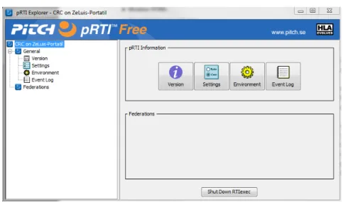
4.5 Pitch pRTI Graphical Interface . . . 33
4.6 Sample Federation Execution . . . 33
5.1 Simple Simulink Model . . . 38
5.2 Interaction diagram of the test example . . . 40
5.3 Integrated architecture within TraSMAPI . . . 42
5.4 Interaction diagram of the test example . . . 43
5.5 HLA Implementation Architecture . . . 46
5.6 Diagram flux of federation execution . . . 49
6.1 Pitch pRTI GUI with connected federates . . . 52
6.2 Simulation execution in both simulation tools . . . 53
6.3 Data information exchanged between federates . . . 54
6.4 Aliados network for test-bed experiments. . . 55
6.5 Total Power average (in KW) . . . 56
6.6 Necessary Energy to perform the trip (in KWh) . . . 56
6.7 Total Battery Charging energy during the trip (in KWh) . . . 57
6.8 Total Braking Kinect Energy dissipated during the trip (in KWh) . . . 57
6.9 Total Super Capacitor Charging Energy during the trip (in KWh) . . . 57
6.10 Total Acceleration average (in m/s2) . . . 58
6.11 Necessary Energy to perform the trip (in KWh) . . . 58
6.12 Overall Simulation performance with one electric bus . . . 60
B.1 Field Experiment Results from EBPS . . . 83
B.2 Field Experiment Results from EBPS (continuation) . . . 84
2.1 Perception of M&S from different perspectives . . . 7
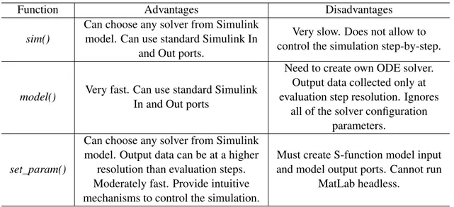
5.1 A comparison between different functions for execute Simulink models simulation 37 5.2 Bus Object Class Representation . . . 44
5.3 Interaction Classes . . . 45
5.4 Interaction Class Parameter . . . 45
5.5 Public and subscribe entities by SUMO and EBPS federates . . . 48
API Application Programming Interface EBPS Electric Bus Powertrain Subsystem FOM Federation Object Model
GUI Graphical User Interface HLA High Level Architecture
IEEE Institute of Electrical and Electronics Engineers ITS Intelligent Transportation Systems
MATLAB MATrix LABoratory M&S Modelling and Simulation OMT Object Model Template RTI Run-Time Infrastructure SOM Simulation Object Model SUMO Simulation of Urban MObility TraCI Traffic Control Interface
TraSMAPI Traffic Simulation Management Application Programming Interface XML Extensible Markup Language
Introduction
In the last decades it has been witnessed a large increase in traffic and transport demand that has created and aggravated capacity problems in the infrastructure causing traffic congestions and delays. Problems in the traffic system have a large impact on almost all areas of economic activity since the flow of people and goods between cities is directly related to the road network [ARS07]. Furthermore, traffic congestion affects not only the welfare of the citizens from the economic point of view but is also related to their health status both psychological, due to stress accumulated during their travels, and physical due to high air pollution levels. In fact, a problem associated with the increasing use of personal vehicles is the emissions. According to the 2009 Urban Mobility Report [SL09] the congestion led urban Americans to travel 4.2 billion hours more, which resulted on 2.8 billion gallons of extra fuel, an increase of more than 50% over the previous decade.
The green house effect, also known as global warming, is a serious issue that we have to face. There has been increased tensions in part of the world due to the energy crisis. Government agencies and organizations try to develop more stringent standards for the fuel consumption and gas emissions through reduction of the congestion on network infrastructures [Sov10]. However, this is no longer regarded as a problem confined only to large metropolitan areas. Currently, the traffic problems typical to densely developed urban areas began to spread to the suburbs as the people move away from the traditional centre city work pattern [Dow04]. In addition, advances in automotive technology have allowed more people to drive which has led to traffic congestion even in small towns.
There is, of course, a diversity of different solutions trying to tackle congestion problems. As congestion begins to occur when the amount of traffic within a road network is approaching its maximum capacity, the most obvious solution is to increase the network capacity [ZY04]. This can be done in several ways, such as building new roads, extending the existing ones and adjusting the speed limit of roads to increase their capacity. However, creating new roads or adding additional capacity to the existing ones can be expensive, time consuming, can cause environmental and social impacts and is not guaranteed that it solves the problem, as demonstrated by Braess’ paradox [Bra68, Mur70]. Moreover, road traffic is growing faster than capacity and is expected to continue to do so if no measures are imposed to limit traffic growth.
Various policy-based methods to reduce road traffic have been attempted, like, for instance, introduced a congestion charge, a system which works by charging motorists who travel into and out of a designated area within certain hours. But these options are not always entirely viable; numerous criticisms including an increased risk of crashes due to speed differences and violation of principles of equality have been levied against this idea [Ye12]. Another attempted solution used for various countries was through the layout of road-networks. The introduction of one-way systems and ring-roads, and the use of road systems that curve and merge into each other rather than perpendicular junctions (roundabouts are a good illustration) are some examples of these attempted [Ty10].
However, the increase in traffic volumes combined with often short distances between intersec-tions requires the adoption of a systems analysis approach to properly address traffic congestion. Often traffic congestion is not the result of excessive traffic, but the result of overlapping bot-tleneck locations. The spillover effect of traffic congestion from one location to another makes inefficient conventional engineering methods [MM01].
In this sense, incentives and investments on public transports as well as research on more eco-sustainable solutions have been performed as attempts to minimize both the air pollution and congestion problems. One of the approaches currently investigated and implemented to provide an eco-sustainable solution for the public transport is related to the employment of electric bus powertrains in metropolitan transportation as an alternative to internal combustion engine buses [UBW+10]. However, there are still open issues related to the consumption of energy and other performance measures for considering the adoption of electric buses in urban scenarios as a cost-effective solution [Mac].
An important aspect in evaluating the performance and adequateness of such vehicles is the fact they are to be in immersed into an urban environment context. That is, a route having many positive elevations or a traffic congestion situation will directly affect the autonomy and perfor-mance of the vehicle.
Alongside ITS (Intelligent Transportation Systems), other concept that has been gaining a great importance in traffic and transportation domain is the simulation concept. The use of com-puter simulations has proved to be a crucial assistance to traditional traffic engineering analysis methods in fully understanding the dynamics of traffic movement and control processes [WS06]. In fact, it allows the prediction of the impact of new solutions before being applied in real sce-narios and also enables the execution of experiments which may be impossible, either due to their excessive cost or consequences [Pur99]. For example, traffic simulation can be used to estimate the impacts at network level of ITS candidate solutions. In this way, one can easily experiment with penetration rates or system settings to create hypothetical future scenarios.
Traffic simulation uses different computational models to represent different domain abstrac-tions. Each of these models characterizes a level of granularity of the real system, depending on the perspective and the type of analysis one intends to perform [IL02]. These models serve for different purposes, and each of them has its own advantages and disadvantages over the others. For example, microscopic models which provide a detailed representation of the traffic process
can simulate to the granularity of a single vehicle but cannot simulate efficiently large-scale traffic networks.
In complex networks, requiring a large amount of input data, the use of a microscopic model results on a tremendous computational cost. In contrast a macroscopic model captures traffic dynamics in lower detail being most suitable for modelling large networks, but failing to capture the behaviour of vehicles at junction level e.g. traffic signal control of an intersection [MSLZ11]. Thus, no model can be completely replaced by another one as each of it bears information for a specific level of resolution.
Traditionally, the various types of simulation tools such as traffic simulators use a specific type of model and, moreover, are used as standalone tools. This leads experts to work separately on different tools and models when the problem is often complex and therefore requires an integrated analysis as well. There are some traffic simulators capable of combining different simulation models (e.g. AIMSUN [Tra] , TransModeler [Cal]). However, most of them are commercial and mainly focus on macroscopic/microscopic integration as they claim. None of them embodies a nanoscopic aspect of the system.
The option of creating a new simulator, or extending an open-source one in order to integrate different types of traffic simulation models could not be a good approach. On one hand, such approach requires an enormous and complex work that would need a very detailed validation without quarantining flexibility and interoperability. On the other hand, there are many simulators each one designed for a specific simulation model which have been used in a great amount of studies and so they are already validated and well accepted.
An interesting way to work around the lack of this kind of integration would be to get simula-tors that implement traffic models of different resolution working together allowing data exchange and thus allowing different types of analyses. In fact, there are some interesting works using com-binations of different simulators for integrating different types of models [YLBO07, CPD+00, DRE02, CH09]. However, none of the applications developed to date are sufficiently generic to being able to easily add new simulation tools without the risk of losing consistency.
1.1
Motivation and Objectives
In order to analyse the adoption of electric buses as a cost-effective solution, it is needed an evaluation of the performance and adequateness of such vehicles while immersed into an urban environment context. Albeit there are different tools and models to assess the behaviour of electric buses, such evaluations often lack the aforementioned integration with the traffic dynamics [Mac]. This work will present a distributed architecture for electric bus powertrain simulation within a realistic urban mobility context. Such a platform will be important for analysing how traffic flow and its dynamics affect the performance of the electric bus when there are obstructions or intense traffic conditions.
Thus, the main objective of this thesis is to study the possibility of integrating microscopic and nanoscopic traffic simulation models and evaluate the advantages that can be achieved on in-tegrated studies. More specifically, it is an intention of this work the integration of two different simulators: the Matlab/Simulink model of an electric bus subsystem (for simulating the consump-tions of an electric vehicle) and SUMO [BBEK11] a microscopic traffic simulator (for simulate the urban traffic conditions under which the electric vehicle should be evaluated).
It is also an aim of this work to study the concepts and the potential of using High Level Architecture (HLA) to interconnect different simulation systems. For last, it will be analysed the influence of drivers’ behaviour in the electric engine consumptions.
1.2
Thesis structure
The report is structured as follows:In this chapter, an introduction to the subject of work and most important goals to achieve are presented.
Chapter 2, will cover some background to the subject of modelling and simulation as well as distributed simulation where the HLA concepts are introduced. Furthermore it will present a deeper overview on traffic simulation and its different simulation models, and some related works related with the integration of the different types of these models.
Chapter 3, starts with a recall of the problem definition and objectives of the project. After this, is presented the architectural solution, within HLA concepts, along with its fundamental issues to be addressed. Also, a methodological approach is established;
Chapter 4 introduces the software package used on the development of the proposed solution. In Chapter 5 is presented the main implementation steps of the solution for the encountered problems and aforementioned requirements.
In Chapter 6 some functionality and performance tests to the integration implementation are performed, and its results are discussed. Furthermore, a test-bed is presented to highlight the potential of the developed framework for integrated studies.
Chapter 7 concludes the document depicting the main contributions, final remarks and future work.
Literature Review
This chapter will explore the background concepts needed for a better understanding of the project and its position respect to other similar works in the field. It starts presenting some concepts about simulation in general before moving to a more specific scope such as traffic domain simulation. Afterwards, related work on the integration of different models in traffic domain is presented. Finally, background concepts of distributed simulation using the High Level Architecture approach and its application in civil domain are presented.
2.1
Modelling and Simulation Overview
First of all, it is important to introduce the concept of system in the M&S context. According to Schmidt and Taylor [ST70], a system is a collection of entities, e.g. people or machines that act and interact together toward the accomplishment of some logical end. In practice, the components of a system depend on the scope and objectives of a particular study.
The "definition" of the collection of entities in a system is a matter of perspective. That is, such collection that composes the system in a given study might be only a subset of the overall system for another one. For example, if one wants to study the number of employees that a restaurant needs, to provide an adequate service to its customers, the system can be defined by the employees and the customers that are being served. On the other hand, if one wants to include, the logistics of the restaurant, the necessary entities have to be added to the system [LK91].
A first overview to the whole concept of Modelling & Simulation (M&S) is provided in order to start justifying the motivation behind this work.
In the literature there is not a unique definition for M&S. Rather, since the very first definition, each domain area and scientific field, within or related to the M&S discipline, tends to define with its own perspective the general framework that covers this discipline. The Merriam-Webster On-Line Dictionary defines simulation as "the imitative representation of the functioning of one system or process by the functioning of another". Maybe, in a more methodological way, one
could say that simulation is the imitation of some real entity, object, state of output, or process over time that represents certain features or behaviours of the selected physical or abstract system. This means that to determine how an actual system function and perform, we would build a model of the system and observe how the model operates [Mar97].
Since decades, the development, analysis and experimentation with models are the basic tools of science and applied systems in economy and industry. Modelling is essentially the development of a model as a representative of a system, or better, the process of producing a model of it. A model is a representation of the structure and operation of some system of interest. It is similar to, but simpler than the system it represents [Rob07]. One purpose of a model’s usage is for helping the modeller to predict the effects that changes in the system can provoke. On the one hand, a model should be a close approximation to the real system and incorporate most of its relevant features. On the other hand, it should not be so complex that makes it impossible to understand and experiment with it. A good model is a judicious trade-off between realism and simplicity [Sar05]. An important issue in modelling is model validity. Model validation techniques include simulating the model under known input conditions and comparing model output with system output.
A simulation of a system is mainly the execution of a model of the system, but not only. As a matter of fact simulation is rather an engineering process in which the model operation is one of the steps. A well-specified working process that guides model development and usage should define which steps have to be performed, which documents and results have to be delivered in what phase of the study. Having a definitive approach for conducting a simulation study is critical to the study success in general and to developing a valid model in particular [Car04]. The model can be reconfigured and experimented with; usually when it is impossible, expensive or impractical to do in the system it represents. The operation of the model can be analysed, and thus, properties concerning the behaviour of the actual system or its subsystem can be inferred. In its broadest sense, simulation is a tool to evaluate the performance of a system, existing or proposed, under different configurations of interest and over long periods of time.
Thus, simulation is used before an existing system is altered or a new system built, to reduce the chances of failure to meet specifications, to eliminate unpredicted tie-up, to prevent under or over-utilization of resources, and to optimize system performance. For instance, simulation can be used as what-if scenarios generator to answer questions like: What is the best design for a new transportation network? What are the associated resource/costs requirements? How will a transportation network perform when the traffic load increases by 50%? How will a new traffic control algorithm affect its performance? What will be the impact of link congestion over the performance of an electric motor operation [ZPK00]?
According to practitioners and researchers, simulation modelling and analysis is one of the most frequently used operations research techniques. When correctly used, simulation modelling and analysis makes it possible to:
• Obtain a better understanding of the system by developing a mathematical model of a system of interest, and observing the system’s operation in detail over long periods of time.
• Test hypotheses about the system’s feasibility.
• Compress time to observe certain phenomena over long periods or expand time to observe a complex phenomenon in detail.
• Study the effects of certain informational, organizational, environmental and policy changes on the operation of a system by altering the system’s model; this can be done without disrupting the real system and significantly reduces the risk of experimenting with the real system.
• Experiment with new or unknown situations about which only weak information is available.
• Identify the "driving" variables - ones that performance measures are most sen-sitive to - and the interrelationships among them.
• Identify bottlenecks in the flow of entities (material, people, etc.) or information. • Use multiple performance metrics for analysing system configurations.
• Employ a systems approach to problem solving.
• Develop well-designed and robust systems and reduce system development time. Applications of simulation abound in the areas of administration, military, computer and com-munication systems, manufacturing, transportation, health care, ecology and environment, soci-ological and behavioural studies, biosciences, epidemiology, services, economics and business analysis. Each of these application areas can perceive simulation under different perspective. The following Table 2.1 presents the perspectives under of which M&S can be perceived: purpose of use, problem to be solved, connectivity of operations, types of knowledge processing, and philos-ophy of science [Ö09].
Perception with respect to Perceptions of simulation
Purpose of use Perform experiments for: Decision support, Understanding, Education, Training, Entertainment
Problem to be solved Black box perception (M&S is an infrastructure to support real-world activities)
Connectivity of operations Standalone simulation; Integrated simulation (symbiotic simulation)
Types of knowledge processing
Computational activity; Systemic activity; Model-based activity; Knowledge generation activity; Knowledge
processing activity
Philosophy of science Simulation supports and enriches modern scientific thinking Table 2.1: Perception of M&S from different perspectives adapted from [Ö09]
A model construction can be intended to solve a specific problem within a domain. Thus, there may be a number of different models for the same domain, each model complying with the characteristics of a particular problem. A. Law and D. Kelton [LK91] divide simulation models in three classes:
• Static vs. Dynamic Models - Static models are either models of time-independent systems or models of a system at a particular time. Dynamic models are those that represent a system as it evolves over time.
• Deterministic vs. Stochastic Models - Stochastic means random, determined by chance. Models that rely on the generation of random variables in deciding how to change state are stochastic. Every time such a model is executed a dif-ferent result is yield. If the execution of the model continues for many times it will give a measure of variability in the process as predicted by the model. With a deterministic one the assumptions and equations selected define the results. A deterministic model is one in which every set of variable states is exclusively determined by parameters in the model and by sets of previous states of these variables. Consequently, deterministic models perform the same way for a given set of initial conditions. Deterministic models can describe behaviours on the basis of some physical law. For example, the planets move around the sun ac-cording to Newton’s laws and their position can be predicted with great accuracy into the future [Nel].
• Continuous vs. Discrete Models - Discrete models are ones in which the state variables change instantaneously at separated points in time while continuous models are ones in which the state variables change continuously over time. Some authors [ZPK00] make distinction between discrete-event models and discrete-time models. The later are a sub category of the discrete-event models in which all time steps are considered for all elements of the model. Discrete-event models that are not discrete-time models consider only those time steps at which state changes occur. An example of a discrete system is the supermarket system, since state variables, such as the number of clients at the supermarket, only change when he arrives or departs. The movement of a car within a city is an example of a continuous system since state variables such as position and velocity can change continuously over time.
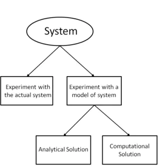
Some set of relationships that compose a model are simple enough to be possible to use math-ematical methods such as algebra or probability theory, to obtain the exact information. However, most real-world systems are too complex to allow realistic models to be evaluated by analytic methods. For these complex systems, the simulation is performed using computational means, in order to evaluate the model numerically and estimate realistic model characteristics. Figure 2.1 illustrates the different ways of studying a system.
Figure 2.1: Ways of systems analysis
2.2
Distributed Simulation
2.2.1 Overview
With the rapid advances being made in computer and software, several new branches appeared in the computer simulation domain. One of these branches is distributed simulation. Distributed sim-ulation refers to technologies "that enable a simsim-ulation program to execute on a computing system containing multiple processors, such as personal computers, interconnected by a communication network" [Fuj01]. The goal for distributed simulation is to provide and facilitate interoperability and reusability of heterogeneous simulation systems. This objective is supported by the arrival of the High Level Architecture concept. HLA provides for the first time a real industry standard which aims interoperability for a wide range of simulation systems and applications.
2.2.2 HLA Concepts
The HLA is an IEEE (Institute of Electrical and Electronics Engineers) standard software de-veloped to provide a common architecture for distributed modelling and simulation (M&S). It is a component-based software architecture that addresses the interoperability and reusability of different models and units of simulations, and offers time management interoperability as well [KDW00]. In order to facilitate interoperability and reusability, HLA differentiates between the simulation functionality provided by the members of the distributed simulation and a set of basic services for data exchange, communication and synchronization.
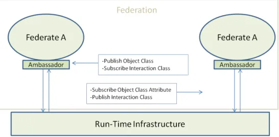
Architecture and Components
In HLA, every participating application is called federate, and these entities can interact with each other within a federation. A federation can be seen as a set of federates acting together
in a distributed simulation to achieve a certain objective.There are three main components that comprise HLA:
• Federate Interface Specification • Framework and Rules
• Object Model Template Specification
The HLA Framework and Rules is the set of rules that must be obeyed to ensure the proper interaction of federates within a federation. These rules must be unchanged across all the simula-tion units as they define the overall architecture. They also define the responsibilities of federates and federation. There are five rules for federates and other five to federations.The definition and description of each rule is available in [IEE10b].
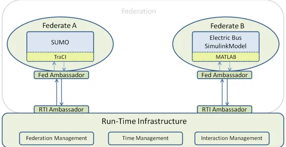
The HLA Federate Interface Specification describes the services which federates have to use for communicating with others. This communication is always made through a middle-ware struc-ture, known as Run-Time Infrastrucstruc-ture, which provides the essential building ground for the soft-ware developers. The interface specification describes which services a federate can use and which services it has to provide [IEE10a]. In order to establish the interaction between federates and the Run-Time Infrastructure (RTI), the concept of ambassador is used. Ambassadors are objects that have the methods needed by the participants for performing communication. So, federates com-municate with the RTI using its ambassador as an interface. Figure 2.2 illustrate the described concepts.
The HLA Object Model Template Specification describes the format and syntax of the data transferred between federates. This data exchange is represented in the form of object class and the two types of object exchange are Object Class and Interaction Class. The first one contains the shared information within federation that persists during the run time. The second one, contains the sent and received information between federates. This component defines the object template data that all simulation unit needs to use in order to exchange data with each other [IEE10c].
2.3
Simulation in Traffic and Transportation Domain
One of the major problems facing transportation engineers and urban planners is that of predicting the impact of given transportation scenarios. For decades, the use of simulation methodologies in Transportation Systems field is widely acclaimed. If one looks for current transportation state in urban scenarios, high traffic saturation levels due to the increasing demand and a not-optimized transportation planning is evident [YCC10]. Thus, computer models are widely used in traffic and transportation system analysis, with a variety of applications from scientific research to planning, training and demonstration.
Traffic simulation tools aim not only to deal with undesired events as mentioned above, but also to generate scenarios, optimize control, and predict network behaviour at the operational
Figure 2.2: HLA’s Functional Architecture
level. However, for the same domain there are a great variety of models, each one representing a different abstraction of it.
In fact, each person has its own way of seeing things, its own point of view over a particular scenario. Thus, each analyst has his own perspective over a specific problem and needs to see through that point of view to be capable of analyse that problem. So, each simulation model is an abstraction of the domain that tries to represent a specific perspective for any specific kind of experts.
After some years of research in traffic flow and the application of its findings to the planning and management of traffic, the discipline has developed a wide variety of methods and tools it can use. For an overview of the state of the art in traffic flow research, see [May90], [Dag97] or [GRM97]. There exist a large number of models, and they are usually characterised by the level of detail in which they describe the traffic processes. As said before, models are classified into different categories depending on the level of detail that represents. Macroscopic, mesoscopic, microscopic and nanoscopic are these categories. Figure 2.1 illustrate the different granularities.
2.3.1 Macroscopic Models
Macroscopic models describe traffic at a high level of aggregation such as flows or densities. These flows are the number of vehicles that pass through a certain road per hour. However these kinds of models do not consider the constituent parts of that flow such as the vehicles. Macroscopic mod-els such as the LWR model [LW55] use differential equations to formulate relationships among traffic flow density. These equations describe traffic flow density like flows in fluids or gases, and therefore, its solution can be obtained through simulation.
In short, macroscopic models only deal with the flow of traffic which made them good for a large and complexes networks analyses. It is useful for route planning and has a lower compu-tational cost compared with the other models, but fails to capture the individual behaviours and
Figure 2.3: The different simulation granularities; from left to right: macroscopic, microscopic, nanoscopic (within the circle: mesoscopic) [KHWR02]
detailed situations of traffic [Bur04].
2.3.2 Mesoscopic Models
Mesoscopic models fill the gap between macro and micro models, they normally describe traffic entities at a high level of detail, but their behaviour and interaction are in a lower level of detail. In mesoscopic model, vehicles can be grouped in packets, which are routed through the network and are treated as one entity. Other paradigm is that of individual vehicles that are grouped into cells to control their behaviour. The cells traverse the link and vehicles can enter and leave cells when needed, but not overtake [Bur04].
2.3.3 Microscopic Models
Microscopic models have a more detailed representation of the traffic than macroscopic ones. These models describe the behaviour of the entities that make up the traffic stream as well as their interactions. In microscopic models, the level of detail goes till the individual behaviour of vehicles, their interaction with each other and with the road network. For that, these models are capable of perceiving some rules of the vehicles’ behaviour such as when a vehicle accelerates, decelerates, changes its lane and chooses or changes their routes to their destinations. Among other some well-known model in the literature are the car-following model [OT04], lane-change model [BACT06], and the route-choice model [Pra09] are the main methods used to determine that vehicle’s behaviour.
These types of models are widely used in analyses of detailed traffic situations such as traffic lights control. However, using these types of models on large and complex roads networks could be an impossible task due to the high computational cost that it requires [Bur04].
2.3.4 Nanoscopic Models
A new trend of traffic simulation is the nanoscopic model which extends the capabilities of three basic components of microscopic simulation: vehicle modelling; vehicle movement modelling; and driver behaviour modelling [DP08].
It is mostly used in autonomous driving and a strictly relationship with automated robotic, be-cause needs to simulate sensors and vehicles constitutes parts. Controls and great improves already has been done on this field. In this paper [FRBR09] is observed great potential in using robotic simulators on autonomous driving field, motivating an information exchange among robotic and traffic study groups.
2.3.5 Distributed Simulation and integrated models in Traffic and Transportation Domain
As has been said before, distributed simulation allows dividing computational efforts to improve simulation performance. Over the past few years, distributed simulation in traffic domain has been widely used in studies of most varied fields.
In fact, with the emergence of the Intelligent Transportation Systems (ITS) more and more studies needs to be made with a great level of detail, leading planners and analysts to use mi-croscopic models rather than mami-croscopic ones. However, mimi-croscopic simulations results in a greater computational effort, being almost impossible to be performed in large urban networks without distributing that effort.
In the literature there are two main focus of distribution in simulating the traffic and transporta-tion domain. The first, is when one want to distribute mechanisms, with decision making capabil-ities, within simulation, (e.g. traffic light agents or driver agents) [WUW+12, FCD12, VO11].
The second one applies when one want to distribute the models among different simulation [LMJR04]. The integration of simulation models, viewed as the coordination and data exchange between different simulators, is a problem to which some approaches have been suggested with diverse motivations and application domains. The main difficulties presented on literature are the data conversion between the different simulation models due to the different paradigm they represent.
As it has been repeatedly mentioned, the necessity of having an integrated tool to represent a system rises from the need for multifaceted analysis of it.
In [SC05] authors consider the integration of macro and microscopic models for the analysis of urban transportation systems. Their concern is based on the advantages of using a macroscopic model for the representation of large-scale networks, and, contemporary, the high resolution in details that can be yield by a microscopic model. They have applied this approach in the analysis of sub-areas that are part of a large macroscopic network, in order to represent detailed design changes as well as traffic management schemes that cannot be treated explicitly by the macro-scopic model. In [SWL11] authors present a real-time algorithm for modelling large-scale traffic using both continuum (macroscopic model) and agent-based (microscopic model) methods. It
is presented some techniques for dynamic coupling of discrete vehicle simulation with the vehi-cle aggregated behaviour of continuum model. Figure 2.4 shows the interface of the integration framework of these models. However, the focus of this work is in terms of visualization perfor-mance rather as analysis tool. On this purpose [MCBB98] present a macro-microscopic approach for the evaluation of the traffic assignment models in transportation planning. [ZDHB09] describe a traffic control framework for emissions by integrating macroscopic traffic flow models with a microscopic emission and fuel consumption model.
Figure 2.4: (a) Interactive 3D visualization of urban traffic; (b) Augmenting a satellite earth map of a metropolitan region with real-time moving traffic consisting of tens of thousands of vehicles using our method [SWL11].
Also in [MSLZ11] a simple transformation methods are analysed to translate the variables parameters between both models. Furthermore, requirements and design principles for specifying and realizing multi-resolution, are introduced in [YLBO07]. Here, a multi-model specification formalism based on graph of models is suggested along with design precepts to enable flexible dynamic model updating. The notion of multi-simulation is also introduced to enable exploratory simulation using various types of multi-models.
Concerning the integration of a microscopic and mesoscopic models, Burghout [Bur04] presents a mesoscopic traffic simulation model, particularly suited for the development of integrated meso-micro traffic simulation models. More related work to integration of this two simulation models are presented by the Shi and Ziliaskopoulos [SZ06] as well as Yang and Morgan [YM06].
With the advent of the vehicular networks, transportation community had to face the require-ment of integrating ad-hoc wireless communication models to the traffic microscopic simulators in order to emulate the network infrastructure for testing the new-type ITS solutions. Among the proposed solutions in the literature are the iTetris framework [GTL+09] and the Veins project [SD08]. Both of the frameworks use SUMO [BBEK11] as traffic simulator.
Another good work concerning microscopic and nanoscopic models, is the one proposed by Martin Adelantado et al [AOC]. It is shown the combining of X-Plane flight simulator, Google Earth browser and the High Level Architecture for evaluating environmental impact of innovative air transport concepts around airports. In [KSSM98] is presented a distributed HLA-based traffic simulation of a nanoscopic model of driver’s behaviour and a microscopic simulator. The authors provide a proof-of-concept prototype of a driver simulator with a microscopic traffic simulator and
a visualization module. An integrated framework that aims coupling robotics and a traffic simu-lator is presented in [PR12]. This work developed an integrated framework enabling autonomous vehicles to be deployed in a rather realistic traffic flow at the same time it simulates all its sensors and actuators. To do so, some modifications were performed on both traffic simulation and 3D simulation environment for robot sensors simulation. The application is distributed, as one com-puter is used to simulating a large traffic environment whereas other comcom-puters simulate single autonomous vehicles that integrates the simulation. In [MSAN11] the model of an electric vehicle engine is embedded into the vehicle model of a microscopic simulator. This study is, to the best of our knowledge, the first attempt to integrate electric vehicle model into a traffic simulation. Although it is a forerunner application, the integration was achieved by performing modifications on the core of the simulators. Thus, this integration is not flexible, and do not allow easy coupling of new simulators or other simulation tools. Also, it doesn’t account for the powertrain as a whole.
2.4
Summary
In this chapter was presented some background concepts that are essential to a better understanding of the motivation and context of this thesis. It was emphasized the importance of modelling and simulation in studies of many different domains, allowing analysis that are impossible to perform in real-world systems. It was also presented the concept of distributed simulation and its historical evolution, which is important to understand the emergence of the High Level Architecture.
Furthermore, the literature review has shown that combination of different models of simula-tion play an important role in traffic and transportasimula-tion domain. It allows planners and analysts to address complex problems while combining the advantages of each simulation model. However, the existing proposals of integration are often application specific. Given this, the interoperability and reusability notions provided by HLA standards are becoming widely studied in civil applica-tions and proved to be an interesting approach for urban traffic domain.
Methodological Approach
3.1
Problem Statement
The necessity for greener public transport has found in the electric bus powertrain a potential solution. However, such vehicles are still far from being cost-effective. For example, as in all of the actual electric vehicle solution, the electric bus powertrain’s driving range is still low respect to the traditional internal combustion vehicle’s autonomy. There are still open issues related to the consumption of energy and other performance measures for considering the adoption of electric buses in urban scenarios as a gainful solution. An important aspect in evaluating the performance and adequateness of such vehicles is the fact of being immersed into an urban environment context. That is, a route having many positive elevations or a traffic congestion situation will directly affect the autonomy and performance of the vehicle.
This thesis’s main objective is to study the viability of combining both, an electric bus engine model and a microscopic traffic simulator. Thus, an integrated tool for analysts to test different set-ups of the electric bus within a controlled environment, and observe its dynamics in urban traffic will be discussed. The following chapter gathers the requirements regarding the combination of different simulation models and describes the application that implements them.
3.2
Integration Requirements Analysis
For the development of a simulation platform that can be used to analyse how the traffic dynamics and the network topology affect the performance of an electric bus a study of the features that the application needs to include, is necessary. Here, the representation of two different systems having different aspects and resolutions is imposed. On one hand, there is the traffic system, that is the road network (expressing the physical infrastructure and the topology) and the vehicle-entities that move on it. On the other hand, the electric bus system is defined in terms of its powertrain subsystem such as the set of battery and traction motor among others.
To address the issues of the traffic system a microscopic modelling approach is required. In these models the level of resolution goes till the individual behaviour of vehicles, the interaction
with each other and with the road network. Instead, for the electric bus system a nanoscopic model is more proper to describe the operations of specific parts and processes of the vehicle.
The integration among them is achieved by associating the electric bus powertrain subsys-tem to a vehicle entity (corresponding to a vehicle of class bus) of the microscopic traffic model. Thus, important criteria for the selection of the simulators (implementing the microscopic and nanoscopic models) are the ease of access to the respective model variables, the application pro-gramming interfaces (API) and communication protocols. For example, a simulator that already implements a communication protocol, providing a good API, allows an easier data exchange.
The satisfaction of the aforementioned requirements will provide a flexible distribution allow-ing a networked access to the simulators core level and thus high-speed data interconnection and exchange between them.
The presented integrated platform might need to support bidirectional communication capa-bilities. Certainly, the traffic simulator has to provide speed variables to the electric bus powertrain subsystem (EBPS) simulator. Albeit, it is not strictly necessary to have the outputs generated from the EBPS simulator sent to the traffic simulator, this could be important in case of a real-time parameters adjustments of the simulated scenario. However, all of these transactions should occur in the same time step.
Another critical issue that must be properly tackled to achieve the desired goal is the syn-chronization of simulators. Although traffic simulators are not implemented with hard real-time constraints, the processing power of today’s computers allow us to consider that this is quite ac-ceptable.
Therefore, given that most acceptable traffic simulators are prepared to support thousands of individual vehicles in real time, at least a frame rate of 10Hz should be achievable to ensure an efficient data exchanging between simulators. If one wants to perform a simulation with more than one electric bus vehicle, then a larger data flow should be expected between the two simulators. Moreover, all step calculations need to be inferior to the overall frame rate of the simulation for a correct user experience.
It must be noted, that the issues cited above are the most obvious concerning the integration of a traffic simulator with an electric bus engine simulator. However, implementation issues may also arise depending on the architecture and the software chosen.
In the following section an architecture towards the integration of the simulators is proposed.
3.3
Proposed Solution
In this section it will be provided a technical design and solution for the integration of a traffic and an EBPS simulation. Taken into account all issues and requirements stated on the former section, a practical solution is proposed below. Firstly, it is presented the chosen software according to the requirements discussed in 3.2 then, the system architecture is explained as well as the methodology used for its development.
3.3.1 Simulation Package Selection
As pointed out previously, the use of two different simulators may be a feasible approach when simulating electric bus powertrain in an urban context.
In order to implement the physical road infrastructure and the traffic dynamics through vehic-ular movements in microscopic level resolution, the SUMO software suite has been considered. SUMO is a highly portable, microscopic road traffic simulation package designed to handle large road networks and has a strong commitment with the academia and research community [SUM].
SUMO is not only just a traffic simulation, but rather a suite of applications which help to pre-pare and to perform the simulation of traffic. As the traffic simulation involves the representation of road networks and traffic demand to simulate in an own format, both have to be imported or generated using different sources [BBEK11]. Although SUMO’s network model is quite coarse respect to similar commercial applications, it still provides a fast execution time and its "remote control" interface (TraCI API) for interaction with external applications raises SUMO to be a good candidate for appraising new traffic control algorithms and for net-wide investigations. By implementing different vehicle types, SUMO also allows the simulation of public transport or emergency vehicle prioritization at intersections [KHRW02].
For the simulation of electric bus operations and driving cycle a mathematical model of an EBPS model implemented in MATLAB Simulink framework [PRRA12] has been considered.
This particular model of the EBPS has been chosen due to the fact that is a FEUP’s project and thus access to the model’s code and data could be achieved. The proposed integrated platform can result in value-added to the R&D project as the relatively new EBPS model can profit by the more accurate analysis in realistic traffic conditions the proposed platform can provide.
As has been mentioned previously, for having a distributed framework is necessary a mech-anism that "puts" the different models implemented in different environment communicating be-tween them. That is, is necessary a middle-ware layer that synchronizes the operations among the models and maps the corresponding variables and services of each of them.
One of the goals of this thesis project is to devise a generic framework allowing not only an easy interoperability of different tools but also the reusability of legacy models. Two approaches have been considered in designing the models’ communication and integration, one based on an in-house developed solution and the other based on the IEEE HLA standards.
The first approach uses the TraSMAPI layer, which provides an abstraction over the micro-scopic traffic simulators allowing real-time communication with them.
The second approach follows the IEEE 1516-2010e HLA standards. The main idea behind the implementation of the HLA guidelines is the promotion of the system interoperability and the reuse of legacy software. While in the first case the synchronization of the models is embedded to simulators, with the HLA approach the synchronization is relied on the use of an HLA/RTI middle-ware (following the HLA standards) and it becomes transparent to the user. For the purpose of the thesis was considered the use of the commercial package Pitch pRTI that implements the above mentioned standards. The advantages of the pRTI over other commercial and free open-source
implementations are the extensive documentation and the user friendly interface that the package provides.
3.3.2 Proposed Architecture
In this section an overview of the proposed system based on the HLA architecture (depicted in Figure 3.1) is provided.
Figure 3.1: System Architecture
This architecture is similar to a simple High Level Architecture one, where four main modules can be identified:
• Run-Time Infrastructure: The middle-ware responsible for the management of all simulation process. The RTI supplies services required by distributed executions, it routes messages exchanged and data exchange between the SUMO and the EBPS federates.
• Federates: The module corresponding to the HLA compliant simulation enti-ties. For the proposed architecture these are SUMO and EBPS model
• RTI Ambassador: Is as specific interface for communication with the RTI. Therefore, it is used whenever one wants to perform calls to the RTI. This inter-face is already implemented by the chosen RTI, which in this case is the Pitch pRTI.
• FED Ambassador: Is a specific interface allowing RTI to communicate with the federate. Unlike the RTI ambassador, this interface shall be implemented by the federate developer and it is code language specific. The RTI will deliver interactions to federate by performing calls to its Federate Ambassador.
Each federate represents an HLA compliant simulation entity. The compliance is achieved using the federate ambassador interface to exchange data between the RTI and the simulation tool. In this way, the RTI can communicate with the simulation tool through the federate ambassador methods.
Internally each federate comprises a simulation tool, and should ensure the communication between federate ambassador and its tool.
As can be seen in Figure 3.1, the communication between "Federate A" ambassador and SUMO is performed through SUMO’s API. In this sense, whenever simulation data are required, the RTI ambassador performs calls to federate ambassador that communicate with SUMO through TraCI.
In a similar way the communication between "Federate B" ambassador and Simulink model is performed through MatLab, the Simulink’s API.
3.3.3 Prototype Development Planning
In this section it will be presented the methodology for prototype’s development describing the proposed framework. Here, it will be identified the main tasks and described the objectives and methods of each one. The work development was divided into twelve main tasks, each one with its specific objectives described below.
Task 1: Build communication between a Java external application and Matlab
Create a simple Java application that communicates with Matlab, sending it two numbers and get the sum of them as return.
Simple development description: Create sockets to establish the communication between the two applications. Implemented sockets on both Java and Matlab applications as a client-server architecture.
Task 2: Control the Simulink model by an external application through Matlab
Creating a simple Simulink model and control its simulation by an external application using Matlab’s methods as API for Simulink.
Simple development description: Create in Simulink model a simple model that receives a number as input and returns twice that number as output. Study what Matlab’s methods could be used to control the Simulink model, and run the model step-by-step while introducing news inputs.
Task 3: Design a simple scenario for SUMO
Create a simple scenario for simulation, with one bus vehicle;
Simple development description: Create the necessary files for the road network implementa-tion in SUMO. Also include some bus stops as well as the bus vehicle itself.
Task 4: Build communication between a Java external application and SUMO
Create a simple Java application that communicates with TraCI, to obtain the speed of a car at each time step.
Simple development description: Use Java sockets to establish the communication with TraCI. Then use the necessary methods, provided by this API, to get the speed of a specific vehicle in SUMO simulation.
Task 5: Install the Pitch pRTI
Download and install Pitch pRTI and run the provided example.
Simple development description: This task aims the installation of the RTI and the execution of an example. The Pitch pRTI package download provide set of examples useful to understand the concepts and architectures of federates an its communication methods with the RTI.
Task 6: Create FOM for the federation intended
Create the FOM file needed to the execution of the federation.
Simple development description: Create the Federation Object Model file in order to execute the federation. In this file the Interaction Classes, the Object Classes, the attributes of each class and the variables types should be defined.
Task 7: Create Federate Ambassador for SUMO
Create the Federate Ambassador for SUMO in order to communicate with RTI.
Simple development description: Implement all the needed methods of federate ambassador standards for SUMO’s federate.
Task 8: Create Federate Ambassador for MATLAB/Simulink
Create the Federate Ambassador for MATLAB/Simulink in order to communicate with RTI. Simple development description: Implement all the needed methods of federate ambassador standards for MATLAB/Simulink’s federate.
Task 9: Integrate Simulink with SUMO through RTI
Create the federation and run the both, SUMO and MATLAB/Simulink federates.
Simple development description: Execute the RTI, create the federation, execute both feder-ates to join the federation. Execute the simulation and destroy the federation at the end.
Task 10: Execute Simulink model under TraSMAPI control
Simple development description: Implement in TraSMPI the API methods for Simulink as done to other simulators (SUMO, ITSUMO [TARO12] and AIMSUN).
Task 11: Integrate Simulink with SUMO through TraSMAPI
Run both SUMO (with a simple road network) and Simulink model from TraSMAPI
Simple development description: Create the simulation management to control and coordinate both simulations. Run both simulators from TraSMAPI and execute the integrated simulation. Task 12: Test and validation
Perform tests to validate de integrated framework.
Simple development description: Perform both under TraSMPAI and HLA simulations and compare the obtained results for HLA integration validation. Run the HLA integration with two different driver behaviour to evaluate the performance of the electric engine in different situations.
3.4
Summary
Correctly defining the requirements was fundamental for identifying the required steps to develop a solution for the integration of a microscopic traffic simulator with an electric bus subsystem simulator. In this chapter, was presented these requirements as well as the proposed solution architecture. Furthermore, a brief explanation of the identified tasks, in order to fully develop the aforementioned architecture, was presented. In the following chapter a more technical overview of the prototype model will be detailed.
Development Software Overview
In the former chapter, a comprehensive overview of current issues for the integration of simulators was presented along with the requirements for the solution to address them. This chapter describes the chosen software for development the aforementioned solution. First, the SUMO traffic simu-lator and EBPS are introduced as the main simulation tools. Finally, TraSMAPI and Pitch pRTI are presented as middle-ware solutions for the integration of both simulators.
4.1
SUMO Microscopic Traffic Simulator
SUMO (Simulation of Urban MObility) is a well-known open-traffic microscopic traffic simula-tion package that appears for the first time in 2001. Today SUMO is already in its 0.16 version and is one of the most commonly used microscopic traffic simulator in the research community. In this chapter, a brief description of SUMO is presented as well as an brief overview of its architecture. Furthermore, it is made a description of necessary SUMO’s network files in order to perform a traffic simulation.
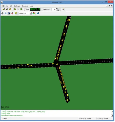
SUMO became an important tool in many researches within urban traffic and transportation domain. It have gained its place among the academic community with many of scientific papers referring to it. Today, SUMO is not just a traffic simulation, but rather a suite of applications which help to prepare and to perform the simulation of traffic. In fact SUMO has been used in several research topics such as route choice [DPW10], traffic light algorithm [MSTR12, GNAO12, KBM+05] or simulating vehicular communication [LC08, DSN08, LTV+06], among others. Fig-ure 4.1 illustrates a typical simulation scenario on SUMO.
SUMO is a pure microscopic traffic simulation. At each vehicle is associated an identifier, the departure time, and the vehicle’s route through the network. It is also possible to describe each vehicle in more detail. For example, it is possible to define arrival properties of the vehicle, which lane it could use, its velocity and its position. Also, each vehicle can be assigned to a vehicle-type which describes its physical properties and variables of the used movement model. This is an important feature for this work since it allows us to make an one to one association between the vehicle bus in SUMO and the EBPS of the electric bus. Sumo follows time-discrete simulation
Figure 4.1: Example of the Simulation of Urban Mobility (SUMO) traffic simulator interface
having a simulation step of 1 second by default. It is also space-continuous and internally, each vehicle’s position is described by the lane the vehicle is on and the distance from the beginning of this lane.
As the traffic simulation SUMO requires the representation of road networks and traffic de-mand to simulate in an own format, both have to be imported or generated using different sources. Regarding the network, there are different ways for creating road networks for SUMO. It can be either generated using an application named netgen or generated by importing a digital road map. The road network importer netconvert allows to read networks from other traffic simulators as VISUM, Vissim, or MATsim. It also reads other common formats, as shape-files or Open Street Map [KHRW02].
With respect to the traffic demand, there are some applications for SUMO that allow the gen-eration of traffic flux over the networks. jtrrouter is a route computation application that uses definitions of turn percentages at intersection for computing routes through the network. Such an approach can be used to set up the demand within a part of a city’s road network consisting of up to ten nodes. A further application, dfrouter, computes routes by using information from loop detectors. This approach is quite successful when applied to highway scenarios where the road network does not contain rings and the highway entries and exits are completely covered by detectors [BBEK11].
![Figure 2.3: The different simulation granularities; from left to right: macroscopic, microscopic, nanoscopic (within the circle: mesoscopic) [KHWR02]](https://thumb-eu.123doks.com/thumbv2/123dok_br/19175924.943175/32.892.265.582.136.353/figure-different-simulation-granularities-macroscopic-microscopic-nanoscopic-mesoscopic.webp)
![Figure 4.4: Modular structure of TraSMAPI and overall architecture of MAS (from [TARO12])](https://thumb-eu.123doks.com/thumbv2/123dok_br/19175924.943175/51.892.244.691.138.570/figure-modular-structure-trasmapi-overall-architecture-mas-taro.webp)