UNIVERSIDADE DA BEIRA INTERIOR
Faculty of EngineeringPerformance Assessment of
Aggregation and Deaggregation
Algorithms in Vehicular
Delay-Tolerant Networks
João Nuno Gabriel Isento
Submitted to the University of Beira Interior in candidature for the Degree of Master of Science in Informatics Engineering
Supervised by Prof. Doutor Joel José Puga Coelho Rodrigues
Department of Informatics University of Beira Interior
Covilhã, Portugal http://www.di.ubi.pt
Acknowledgements
First of all, I would like to thank to Professor Joel José Puga Coelho Ro-drigues for all the support, for the constant words of encouragement and for supervising my Master’s Thesis. I also would like to thank for the opportunity to belong to his research group, Next Generation Networks and Applications Group (NetGNA).
I am most grateful to the University of Beira Interior, the Instituto de Tele-comunicações, Next Generation Networks and Applications Group (NetGNA), Covilhã Delegation, Portugal in the framework of the Project VDTN@Lab, and by the Euro-NF Network of Excellence from the Seventh Framework Programme of EU in the framework of the Specific Joint Research Project VDTN, for many kinds of all the support that was given to me. Additionally, I’d like to thank to all members of the VDTN team, but especially to my colleagues Bruno Silva, João Alfredo, and Vasco Soares for all the daily support and help.
My highest gratitude to all my family, especially to my parents and sis-ter, for being a constant source of support, love, and inspiration. I am forever indebted to them.
Abstract
Vehicular Delay-Tolerant Networks (VDTNs) are a new approach for vehic-ular communications where vehicles cooperate with each other, acting as the communication infrastructure, to provide low-cost asynchronous opportunistic communications. These communication technologies assume variable delays and bandwidth constraints characterized by a non-transmission control proto-col/internet protocol architecture but interacting with it at the edge of the network.
VDTNs are based on the principle of asynchronous communications, bundle-oriented communication from the DTN architecture, employing a store-carry-and-forward routing paradigm. In this sense, VDTNs should use the tight network resources optimizing each opportunistic contact among nodes.
At the ingress edge nodes, incoming IP Packets (datagrams) are assembled into large data packets, called bundles. The bundle aggregation process plays an important role on the performance of VDTN applications. Then, this paper presents three aggregation algorithms based on time, bundle size, and a hybrid solution with combination of both. Furthermore, the following four aggregation schemes with quality of service (QoS) support are proposed: 1) single-class bun-dle with N = M , 2) composite-class bunbun-dle with N = M , 3) single-class bunbun-dle with N > M , and 4) composite-class bundle with N > M , where N is the num-ber of classes of incoming packets and M is the numnum-ber of priorities supported by the VDTN core network. The proposed mechanisms were evaluated through a laboratory testbed, called VDTN@Lab. The adaptive hybrid approach and the composite-class schemes present the best performance for different types of traffic load and best priorities distribution, respectively.
Keywords
Delay-Tolerant Networks, Fragmentation, Performance Assessment, Rout-ing, Vehicular Ad Hoc Networks, Vehicular Delay-Tolerant Networks, Testbed.
Contents
Acknowledgements iii Abstract v Keywords vii Contents ix List of Figures xi Acronyms xiii 1 Introduction 1 1.1 Focus . . . 1 1.2 Objectives . . . 3 1.3 Main Contributions . . . 3 1.4 Dissertation Structure . . . 3 2 Related Work 7 2.1 Introduction . . . 7 2.2 Delay-Tolerant Networks . . . 72.3 Vehicular Delay-Tolerant Networks . . . 8
2.4 Available Aggregation approaches . . . 11
2.5 Proposed Aggregation Solutions . . . 13
2.5.1 Traffic Modeling . . . 14
2.5.2 Aggregation Mechanisms . . . 15
2.5.3 Generalized Bundle Assembly Framework for QoS Support . 18 2.5.4 De-aggregation method . . . 20 2.6 Summary . . . 20 3 Research Methodology 23 3.1 Introduction . . . 23 3.2 Vehicular Testbeds . . . 23 3.3 VDTN@Lab Testbed . . . 25 3.4 Summary . . . 29
4 Performance Evaluation and Demonstration 33
4.1 Introduction . . . 33
4.2 Network Scenario . . . 33
4.3 Performance Evaluation of Aggregation and Deaggregation Mech-anisms . . . 34
4.3.1 Aggregation Algorithms . . . 34
4.3.2 QoS Support Schemes . . . 35
4.3.3 Network Performance Analysis . . . 36
4.4 Summary . . . 38
5 Conclusion and Future work 41 5.1 Conclusion . . . 41
5.2 Future work . . . 42
List of Figures
1.1 Illustration of a typical vehicular network. . . 2
2.1 Illustration of the DTN store-carry-and-forward paradigm. . . 9
2.2 Comparison of TCP/IP, DTN, and VDTN architectures . . . 10
2.3 Control information and data bundles exchange. . . 11
2.4 Illustration of incoming traffic models: a) Poison; b) Self-Similar Traffic. . . 14
2.5 Illustration of the bundle assembly process. . . 16
2.6 Proposed aggregation algorithms with QoS support: (a) Single-class bundle with N = M = 4; (b) Composite-Single-class bundle with N = M = 4.;(c) Single-class bundle with N = 4 and M = 2; (d) Composite-class bundle with N = 4 and M = 2. . . . 20
3.1 UML activity diagram of a mobile node, describing the control plane and data plane interaction, coordinated by decision module 27 3.2 A mobile node created with a Lego MINDSTORMS NXT robot and a coupled netbook. . . 28
3.3 Illustration of VDTN nodes interaction: (a) a mobile and a ter-minal node establishing contact, (b) a mobile and a relay node establishing contact and (c) two mobile nodes establishing contact. 28 3.4 UML class diagram illustrating the main classes andimportant re-lationships in VDTN testbed . . . 29
4.1 VDTN@Lab laboratory testbed scenario. . . 34
4.2 Performance evaluation of proposed algorithms: Average aggre-gation delay as function of traffic load for different traffic loads (low , medium, and high). . . 35
4.3 Performance evaluation of proposed algorithms: Distribution of bundle priorities after aggregation algorithms. . . 36
4.4 Bundle average delay as function of traffic load for timer-based algorithm. . . 37
4.5 Bundle average delay as function of traffic load for threshold-based algorithm. . . 37 4.6 Bundle average delay as function of traffic load forhybrid algorithm. 37
Acronyms
BAD Bundle Aggregation and De-aggregation BSC Bundle Signaling Control
DTN Delay-Tolerant Network
DTNRG Delay-Tolerant Network Research Group UBI Universidade da Beira Interior
FIFO First-In-First-Out
GPS Global Positioning System
IEEE Institute of Electrical and Electronics Engineers IP Internet Protocol
LIFO Last-in-First-Out
LTP Licklider Transmission Protocol MAC Media Access Control
MANET Mobile Ad hoc Network MTU Maximum Transmission Unit
QoS Quality of Service
RLSMP Region-based Location Service Management Protocol TCP Transmission Control Protocol
TTL Time-To-Live
UML Unified Modeling Language UDP User Datagram Protocol VANET Vehicular Ad hoc Network
Introduction
Chapter 1
Introduction
1.1
Focus
Vehicular networking has attracted growing research attention in the last years and it has shown a great potential for application to a wide range of real-world scenarios. Examples include networks to disseminate information advertisements or safety related information [?, ?, ?], networks to distribute multimedia content [?, ?], and monitoring networks for data collection [?]. Ve-hicular networks can also be employed to provide connectivity to remote rural communities and regions [?, ?, ?, ?, ?, ?], or to assist communication between rescue teams and other emergency services in catastrophe hit areas lacking a conventional communication infrastructure [?]. Figure 1.1 illustrates a typical vehicular network scenario. However, the establishment of network connec-tivity among vehicles and between vehicles and roadside infrastructure faces challenging connectivity issues. Most of them arise from the high mobility of vehicles, which is responsible for a highly dynamic network topology, and to short contact durations [?, 33]. Limited transmission ranges, physical obstacles, and interferences lead to disruption and intermittent connectivity [?]. Further-more, the large distances usually involved and low node densities contribute to network partition. Therefore, a contemporaneous end-to-end path from source-to-destination often does not exist.
The related literature offers several available approaches to solve the problem of providing communication in vehicular networks. Vehicle ad hoc net-works (VANETs) [?, ?] were proposed as a special type of ad hoc netnet-works for inter-vehicular communications. However, conventional routing schemes for VANETs assume end-to-end connectivity. Thus, they are not able to deal with network disconnection, partitions, or long-time delays [?,?,?]. These limitations were overcome by applying the store-carry-and-forward paradigm of the delay-tolerant network (DTN) architecture [8], creating the concept of “DTN-enabled VANETs” [?, ?]. In a DTN-based network, data delivery is increased by allowing nodes to store data when there is no contact with other nodes, to carry it until meeting other nodes, and forwarding it based on a routing scheme.
More recently, vehicular delay-tolerant networks (VDTNs) were proposed as an alternative network architecture for sparse vehicular networks [7]. VDTN
Introduction
Figure 1.1: Illustration of a typical vehicular network.
architecture also adopts a store-carry-and-forward paradigm from DTNs. Nonethe-less, it distinguishes itself from the DTN architecture by positioning the bundle layer between the network and data link layers, introducing a clear separation between control and data planes using out-of-band signaling.
Designing protocols for VDTNs poses a number of technical challenges due to the nature of vehicular environments and to a variety of factors including node heterogeneity, node interactions, node cooperation, and limited network resources. Usually, researchers propose and evaluate new services and pro-tocols using simulation and theoretical analysis techniques. However, these techniques typically abstract many details of the real-world, and these sim-plifications tend to impair performance in reworld environments. Thus, al-though simulation and theoretical analysis are helpful in a preliminary evalu-ation of new protocols and algorithms, it is essential to implement, test, and evaluate them in a testbed (prototype) network for performance assessing under real-world conditions. In this sense, this work also addresses the performance evaluation of aggregation and de-aggregation algorithms for VDTNs through a testbed, called VDTN@Lab. The motivation for this prototype is to provide a framework for demonstration and validation of the VDTN architecture, allowing the development, performance evaluation, and validation of new services and protocols, as well as VDTN applications. The proposed testbed features (i) an emulation capability allowing live experiments with prototyped hardware and software embedded into robotic cars, computers/laptops, and netbooks; (ii) an integrated environment capable to emulate VDTN protocol stacks, services, and
Introduction
applications; and (iii) operation under emulated realistic operating conditions.
1.2
Objectives
The main objective of this dissertation is the presentation of a detailed study about the available aggregation and deaggregation approaches for vehic-ular networks, and their impact on the performance of VDTN networks. To ac-complish this main objective, the following partial objective were identified and performed: a detailed review of the state-of-the-art in aggregation approaches for vehicular networks and their application to VDTNs; Design and creation of modules for VDTN@Lab to support the studied aggregation algorithms; Perfor-mance evaluation of the studied aggregation mechanisms for VDTNs; Finally, dissertation writing summarizes all the above-mentioned partial objectives.
1.3
Main Contributions
This section is devoted to the scientific contributions of this dissertation to the state-of-the-art on VDTNs, more precisely about aggregation algorithms. The first contribution of this dissertation is the presentation of an overview about all the main aspects and features of VDTN networks, which was published in IEEE Intelligent Transportation Systems Magazine, 2013 [?].
The first contribution of this dissertation is the construction, validation and deployment of a VDTN testbed, called VDTN@Lab, which was published in EURASIP Journal on Wireless Communications and Networking, 2012, with an impact factor of 0.54 [?].
The second contribution elaborates an initial study about aggregation algo-rithms on VDTNs, which was presented at 8th IEEE International Conference on Mobile Ad-hoc and Sensor Systems (IEEE MASS 2011), Valencia, Spain, October 17-22, 2011 [?].
The third contribution of this dissertation is a detailed research about ag-gregation algorithms with QoS support, which was presented in 13th Interna-tional Conference, ADHOC-NOW 2014, Benidorm, Spain [?].
1.4
Dissertation Structure
This dissertation is organized in 5 chapters. This chapter, the first, presents the context of the dissertation, focusing on the topic under study, the
objec-Introduction
tives, main contributions and dissertation structure.
Chapter 2 elaborates on the related work about the topic, focusing on ag-gregation and deagag-gregation solutions for the different kinds of above-presented vehicular networks.
Chapter 3 presents the VDTN@Lab testbed used for performance evalua-tion. It also describes the conceptual design and used technologies.
Chapter 4 focuses on the performance evaluation study of the implemented aggregation and deaggregation mechanisms. The performance metrics and net-work scenarios are also described in this chapter .
Finally, Chapter 5 concludes the dissertation and points some directions for future research works.
Related Work
Chapter 2
Related Work
2.1
Introduction
Vehicular networks have emerged as a new wireless network solution due to the advances of wireless technologies and the automotive industry. Vehicu-lar networks can be applied to a wide range of real-world scenarios. For exam-ple, they can be used to provide connectivity to remote rural regions [1, 2] or being used as the communication infrastructure in case of emergency scenar-ios [3]. However, these networks face several problems when considering the establishment of network connectivity among vehicles and between vehicles and roadside infrastructure. Most of the connectivity issues arise from the high mobility of vehicles, which leads to constant changes in the network topology and short contact durations. Another issue that these networks should over-come is the intermittent connectivity and disruption, which is cause by phys-ical obstacles and limited transmission ranges. Moreover, the large distances and low node densities contribute to network partition. Consequently, a con-temporaneous end-to-end path from source to destination often does not ex-ist. In order to overcome the above-presented issues, several approaches were proposed, including VANETs (Vehicular Ad-hoc Networks), DTNs (Delay Tolerant Networks), and VDTNs (Vehicular Delay-Tolerant Networks), that are considered in this work. Afterwards, the state of art about aggregation and deaggregation solutions is presented. It includes aggregation approaches used on optical burst switching networks and vehicular communications.
2.2
Delay-Tolerant Networks
Delay-/disruption-tolerant networking (DTNs) focuses on the design, im-plementation, evaluation, and application of architectures and protocols that intend to enable data communication among heterogeneous networks in ex-treme environments. Examples include interplanetary networks, underwater networks, wildlife tracking networks, sparse wireless sensor networks, people networks, military tactical networks, transient networks, disaster recovery net-works, and vehicular networks.
Related Work
DTNs experience any combination of the following aspects: sparse connec-tivity, frequent partitioning, intermittent connecconnec-tivity, large or variable delays, asymmetric data rates, and low transmission reliability. More importantly, end-to-end connection cannot be assumed to be available. In order to answer to these challenges the DTN Research Group (DTNRG), proposed an architecture (RFC 4838) [4] and a communication protocol (RFC 5050) [5] for DTNs. The DTN architecture [4] introduces a store-carry-and-forward paradigm by over-laying a protocol layer, called bundle layer, above the transport layer, which provides internetworking on heterogeneous networks (regions) operating on dif-ferent transmission media. The bundle protocol [5] is end-to-end, strongly asyn-chronous, message (bundle) oriented.
Application data units are aggregated into one or more protocol data units called ”bundles” by the bundle layer. The idea is to �bundle� together all the in-formation required for a transaction (entire blocks of application-program data and metadata). This minimizes the number of round-trip exchanges, which is useful when the round-trip time is very large. To help routing and scheduling decisions, bundles contain an originating timestamp, a useful life indicator, a class of service assignment, and a length indicator. The bundle protocol also offers an optional hop-by-hop transfer of reliable delivery responsibility, called bundle custody transfer, and an optional end-to-end acknowledgement func-tionality (i.e., �return receipt�). When nodes accept custody of a bundle, they commit to retain a copy of the bundle until such responsibility is transferred to another node.
The store-carry-and-forward paradigm avoids the need for constant con-nectivity. It is used to move bundles across a region, exploiting node mobility. This paradigm, which is illustrated in Figure 2.1, can be described as follows. A source node originates a bundle and stores it using some form of persistent stor-age, until an appropriate communication opportunity becomes available. The bundle will be forwarded when the source node is in contact with an interme-diate node that will be more close to the destination node. Afterwards, the intermediate node stores the bundle and carries it until a suitable contact op-portunity occurs. This process is repeated and the bundle will be relayed hop by hop until (eventually) reaching its destination.
2.3
Vehicular Delay-Tolerant Networks
VDTNs are complex systems where a variety of mobile and fixed nodes can freely interact with each other. Terminal nodes represent the access points to the VDTN network and may be both fixed and mobile (e.g., vehicles that also act
Related Work T+t0 T+t1 T+t2 T+t3 Mobile Node Mobile Node Mobile Node Source Node Destination Node
Figure 2.1: Illustration of the DTN store-carry-and-forward paradigm.
as end points of a communication). Mobile nodes are opportunistically exploited to collect and disseminate data bundles through the VDTN network. They move along roads and carry data that must be delivered to the terminal nodes. Sta-tionary relay nodes are fixed devices with store-and-forward capabilities that are located at road intersections. Mobile nodes interact with them to deposit and pickup data. Relay nodes increase contact opportunities in scenarios with low node density. Hence, they contribute to increase the data bundles delivery ratio, and decrease their delivery delay [6].
In order to support communication in sparse and disconnected vehicular network scenarios, VDTN presents a network architecture based on the follow-ing based design principles [7]: (i) Internet protocol (IP) over VDTN approach; (ii) end-to-end, asynchronous, and variable-length bundle oriented communi-cation; and (iii) separation between control and data planes using out-of-band signaling. Different to DTN architecture proposal that introduces a bundle layer between the transport and application layer to allow the interconnection of highly heterogeneous networks [5], VDTN architecture places the bundle layer over the data link layer introducing an IP over VDTN approach [7]. The protocol data unit at the VDTN bundle layer is called a bundle, wish aggregates several IP packets with several common properties, like the same destination node.
VDTN uses the principle of store-carry-and-forward routing proposed for DTNs [8]. This paradigm solves the problems caused by intermittency, discon-nection and long delays, and can be described as follows. A network node stores
Related Work
a bundle using some form of persistent storage while waiting for a future oppor-tunistic connection. When a communication opportunity arises, the bundle is forwarded to an intermediate node, according to a hop-by-hop routing scheme. This process is repeated and the bundle will be relayed hop-by-hop until even-tually reaches its destination.
VDTN architecture identifies two logical planes (using out-of-band signal-ing), i.e., the control plane and the data plane [7], which are illustrated in Figure 2.2. These planes are logically divided into two layers, the bundle sig-naling control (BSC) layer and the bundle aggregation and de-aggregation (BAD) layer. BSC is responsible for executing the control plane functions such as sig-naling messages exchange, resources reservation (at the data plane), and rout-ing. The data plane functions that deal with data bundles are executed in BAD. These functions include data bundles aggregation/de-aggregation, queuing and scheduling, and traffic classification.
Application Transport Network Link Bundle Link Bundle Link Bundle Signaling Control Transport Transport Application Application Network Network Bundle Aggregation and De-aggregation MAC MAC Physical Physical
Control Plane Data Plane
Figure 2.2: Comparison of TCP/IP, DTN, and VDTN architectures
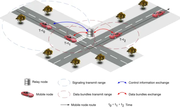
Control plane uses a low-power, low bandwidth, and long-range link, and it is always active to allow node discovery. The data plane uses high-power, high bandwidth, and short-range link, and it is only active during the estimated con-tact duration time, and if there are data bundles to be exchanged between the network nodes according to the routing protocol [7, 9]. Otherwise, the data plane connection is not activated. This approach is considered impor-tant because it not only ensures the optimization of the available data plane resources (e.g., storage and bandwidth), but also allows to save power, which is very important for energy-constrained network nodes such as stationary re-lay nodes [7, 10]. These nodes are usually power-limited since they may run on solar panels or batteries. Figure 2.3 illustrates this concept. At the time t + t0, a mobile node and a relay node detect each other and start exchanging
sig-Related Work
naling messages through the control plane connection. Both nodes use routing information to determine which bundles should be forwarded. Then, the data plane connection is configured and activated on both nodes at the time t + t1. The bundles are exchanged until the time t + t2. The data plane connection is deactivated after that time instant, since the nodes are no longer in the data plane link range of each other.
T+t0
T+t1 T+t2
Relay node
Mobile node
Signaling transmit range Data bundles transmit range
Control information exchange Data bundles exchange Mobile node route t0 < t1 < t2 Time
Figure 2.3: Control information and data bundles exchange.
2.4
Available Aggregation approaches
In this section, several aggregation solutions to real problems in vehicular communications are addressed. These problems show how important the aggre-gation algorithms are to improve the performance of protocols, services, and applications in vehicular networks.
Mobile ad-hoc networks face security risks and energy consumptions issues due to limits resources and its infrastractureless network environment. To per-form a monitoring and detection in a MANET the authors in [11] develop both lossless and lossy aggregation mechanisms to reduce the energy cost and band-width consumption while preserving the detection accuracy. Lossless aggrega-tion intent to reinforce the detecaggrega-tion informaaggrega-tion, in which the de-aggregated information contains the same data as the original one. In the lossy mechanism, the decompressed data contains most of the original information accepting some loss of fidelity. Real-world experiments and simulations are conducted to assess
Related Work
the effectiveness of this solution.
VoIP traffic over mobile ad-hoc networks faces several issues related to the mobility of the nodes and routing protocols introducing latency and packet loss rate. Authors in [12] present several solutions to improve the quality of VoIP calls in MANET environment. One of these solutions relates to aggregate several VoIP frames within a single packet. Due to this feature, and depending on the voice codec used, the performance of the VoIP traffic was improved. Several simulations were performed using the NS-2 simulator with the NS2Voip++ extension and each simulation had the duration of 4000 seconds.
K-hop bandwidth aggregation [13, 14] is proposed for enhance cooperative video streaming over hybrid vehicular ad-hoc networks and 3G/3.5G cellular network. In this approach each member (vehicle) in the same group is known to each other and share the same path and the same destination. The video requests are sent over 3G/3.5G network. However, the bandwidth in this net-work is very limited and not support higher quality video. In order to improve the quality of video playback the requester can ask to other members, called helpers, to cooperatively download the requested video through their cellular network. Then, all video ”fragments” are sent to the requester over ad hoc network. k-hop aggregation solves the problem of discovering the best helpers and how the data is sent to the requester. This approach can get better quality video that cooperative video streaming without the K-hop aggregation scheme. In a vehicular ad hoc network, one of the main issues is the problem of the message routing, where the location of the destination node is unkown due to the high node mobility. One of the best solution for this problem is to use location service protocols. However, these protocols require large vol-ume of signaling overhead which can result in network traffic congestion and high resource consumption. Region-based Location Service Management Proto-col (RLSMP) [15] uses message aggregation enhanced by geographical clustering to minimize the volume of the signaling overhead. In this protocol, each vehicle frequently check its geographical cluster while moving, without any additional communication or delay. RLSMP uses message aggregation to bypass the draw-backs of independent updating and querying messages. The messages are aggre-gated so that data is grouped, resulting in more efficient bandwidth usage and minimal communication overhead. This protocol guarantees scalability with the increase of the number of nodes in the network.
In [16], authors propose an adaptive packet aggregation for header com-pression. Aggregation packets in a vehicular environment can cause redundant information and, therefore, high volume of traffic. This algorithm, first, per-form static header compression, and then aggregate a dynamic number of
pack-Related Work
ets according to the delay constraints. Using the adaptive procedure, the system will adaptively change the number of aggregated packets according to the cur-rent end-to-end delay. Simulation results, using the NS-2 simulator, showed that the proposed aggregation algorithm outperforms the existing schemes in terms of end-to-end delay and packet delivery rate.
In [17–19], the authors intent to study the effect of aggregation of DTN bundles on space communications. This work tries to find if aggregation of mul-tiple DTN bundles has advantages over the default approach of ”one bundle per block”. In space communications, bundles are passed as ”service data units” to Licklider Transmission Protocol (LTP) for transmission. LTP is an end-to-end protocol for deep space communications. These service data unites are encap-sulated in LTP blocks. Then, each LTP block is divide into LTP data segments, according the maximum transmission unit (MTU) size. To reduce the amount of ACK traffic, multiple DTN bundles are aggregated into a single LTP block. The aggregation of multiple bundles has significant advantages over the default approach.
The complete failure of telecommunications infrastructures is a common characteristic when a disaster occurs. A DTN-based solution is presented in [20] in order to aggregate as much information as possible from an area of interest (AoI) within a disaster zone. Users using mobile phones generate messages with disaster-related information and aggregate them with their respective coverage areas into a new message to minimize the overall message collection delay. To prevent duplicate message from users, this system a filter is constructed to drop possible duplicated messages. Through simulation, using a real geographical map, this solution achieved a smaller delay in message delivery.
All of these abovementioned solutions have contributed to the conception and design of the proposed VDTN aggregation algorithms. All of these aggrega-tion schemes show the influence that the packet aggregaaggrega-tion has in vehicular communications.
2.5
Proposed Aggregation Solutions
This section will present a study of traffic modeling and its importance to evaluate the proposed aggregation algorithms for VDTNs. These algorithms will be described and analized. Lastly, some mechanism to QoS support for VDTN networks will be presented.
Related Work
2.5.1 Traffic Modeling
Understanding network traffic behavior is essential for all aspects of net-work design and operation, e.g., component design, protocol design, and re-source provisioning. The bundle assembly mechanisms search the best way to aggregate incoming data packets to bundles in order to minimize the delay time and size of created bundles. To study the performance of these algorithms is necessary to find a viable model that reproduces the real internet traffic to a laboratory environment. Then, exists two main models to traffic modeling.
Data traffic such as Internet traffic is traditionally modeled as a Poisson process with exponentially distributed time between individual packet genera-tions. The accuracy of this model for simulating data traffic is, however, being questioned in the literature [21]. The first is a Poisson generator with exponen-tially distributed time between individual packet generations (see Figure 2.4 a)). This is a traditional and commonly used model, which developed from early modeling of call arrivals at telephone exchanges. The parameters to this model is shown in (2.1).
P (inter-arrival time = t) = λe−λt (2.1)
Mean inter-arrival time = 1/λ
T1 T2 T3
time T4 T5
OFF Time ON Time OFF Time
Pr(Tx= t) = ↵k↵t ↵ 1 T1 T2 T3 T4 time Pr(Tx= t) = e t a) b)
Figure 2.4: Illustration of incoming traffic models: a) Poison; b) Self-Similar Traffic.
The second model is a self-similar traffic generator, modeled as an ON/OFF source where the time spent in each state fits a Pareto distribution (Figure2.4 b)) with parameters a = 1.2 and k = 1. Packets are generated during the ON
Related Work
periods only, at regular intervals at a rate determined by the specified source activity level. The drawback of the Pareto distribution is that it exhibits infinite variance, so there is a non-trivial probability that the ON time may be longer than the simulation runtime. In (2.2) is shown the parameters to this model.
P (inter-arrival time = t) = αkαt−α−1 (2.2)
Mean inter-arrival time = (α/(α− 1))k 2.5.2 Aggregation Mechanisms
The bundle assembly process can be modeled as a queuing system and is illustrated in Figure 2.5. In this model, the routing module (RM) organize incom-ing packets in buffers accordincom-ing to their destination and QoS requirement. The terminal node assembles these packets into bundles according to a pre-select assembly algorithm. The notations q1, q2, ..., qN are the queues for packets
having the same destination and QoS requirement. Ti is the assembly time of
queue i. Li is the data length of queue i (i is a positive integer and 1 ≤ i ≤ N).
For convenient analysis, some parameters are defined as follows.
Tth : Threshold of the time-based assembly algorithm.
∆t : Incremental value change of the time threshold.
Lth : Threshold of the bundle length algorithm.
∆l : Incremental value change of length threshold.
ξ : Encapsulate coefficient (for QoS class, etc.).
The bundle assembly process can be described as the following five steps. Step 1- Assembly: all incoming packets are sorted and stored in queues q1,
q2, ..., qN;
Step 2 -Judgment: when a packet arrive at queue i, judge whether the threshold is reached or not.
Step 3 -Encapsulation: if the threshold of queue i is reached, then encap-sulate all packets into a bundle;
Step 4 -Buffering: store the bundle in the node buffer according to a first-in first-out prfirst-inciple; and
Step 5 -Transmission: transmit the bundle when a contact opportunity occurs.
Related Work
Figure 2.5: Illustration of the bundle assembly process.
Timer-based Algorithms
Usually, a bundle is created and injected into VDTN network at periodic time intervals in time-based algorithms. These algorithms use a timer to indi-cate an assembly cycle of each queue. There is a fixed threshold Tththat acts as
the primary criterion to create a bundle. Thereby, they provide almost uniform gaps between successive bundles from the same queue into VDTN network. How-ever, the bundle length varies with the offered load. To avoid injecting small bundle or even vacant bundle, the assembly time threshold algorithm can be described cursorily as follows.
1. Initialize: Ti = 0.
2. Waiting: when a packet with length pk_size arrives at i, insert the packet into queue i (if queue i is empty, then start its timer).
3. From i = 0 to N :
if Ti ≥ ξ × Tth then
Encapsulate all packets of queue i into a bundle and store the bundle in the buffer.
Reset Ti = 0 and return to step 2.
else
return to step 2.
Time-based algorithms only consider the encapsulation coefficient and the assembly time. The assembly delay (TaT) of time-based algorithms is equal to
product of ξ and Tth. At a given encapsulation coefficient ξ, TaT is only relating
Related Work
Threshold-based Algorithms
In threshold-based algorithms, a bundle is created and injected into VDTN network once the assembly data length reaches or exceeds the given threshold
Lth. Threshold-based algorithms generate bundles at non-periodic time
inter-vals. A length threshold is used as the primary criterion to create a bundle. The threshold is placed as a limiting parameter on the minimal length or the number of packets contained. In these algorithms, once the threshold is reached, all packets in queue i are assembled into a bundle. The algorithm can simply be described as follows.
1. Initialize: Li = 0.
2. Waiting: when a packet with length pk_size arrives at queue i, insert the packet into queue i and queue renews the assembling data length queue Li =
Li + pk_size
3. From i = 0 to N :
if Li ≥ ξ × Lth then
Encapsulate all packets of queue i into a bundle and store the bundle in the buffer.
Reset Li = 0 and return to step 2.
else
return to step 2.
If we assume that traffic is distributed uniformly for destinations, the ar-rival rate for queue i is equal to Vi/N at a given real-time data arrival rate
Vi from access networks. The assembly data length can be given by (2.3) in
length-based algorithms, Vo is the average date rate from the access networks
to an edge node. The assembly delay (TaL) of length-based algorithms is given
by (2.4). Li = ( Vi N)× Ti = ( Vo× ρn N )× Ti (2.3) TaL = ξ× Lth× N Vi = ξ× Lth× N Vo× ρn (2.4)
Adaptive Hybrid Algorithms
The above two types has some shortcomings under certain conditions. For example, the threshold-based algorithms may will experience a long assembly
Related Work
waiting time when the input traffic is low. Timer-based algorithms solve this problem, however, under high traffic conditions, it will have a larger variance of bundle length. Both types of algorithms are too rigid and not adapt their parameters according to input traffic conditions. Then, some hybrid solution have been proposed. These algorithms can dynamic adjust the time, threshold, or both values, according to the real-time input traffic situation. A general adaptive hybrid algorithm can be depicted as follows.
1. Initialize: Ti Li = 0.
2. Waiting: when a packet with length pk_size arrives at queue i, insert the packet into queue i and queue renews the assembling data length queue Li =
Li + pk_size, (if queue i is empty, then start its timer).
3. From i = 0 to N , calculate Bi = ξ × Ti× Li.
if Li ≥ ξ × Lth or Ti ≥ ξ × Tth then
Encapsulate all packets of queue i into a bundle and store the bundle in the buffer.
Reset Ti = 0, Li = 0 and return to step 2.
if Ti ≥ ξ × Tth or Li ≤ ξ × Lth then Tth = Tth+ ∆tor Lth= Lth− ∆l if Ti ≤ ξ × Tth or Li ≥ ξ × Lth then Tth = Tth− ∆t or Lth= Lth+ ∆l else return to step 2.
2.5.3 Generalized Bundle Assembly Framework for QoS Support
In this section a generalized framework for bundle assembly, based on [22], will be presented. The primary issues are which class of packets and how many of packets of each class to put into a same bundle. To provide QoS support, the bundle assembly policies should take into account the number of packet classes as well as the number of bundle priorities supported in the VDTN core.
Let N be the number of input packet classes at the edge and let M be the number of bundle priorities supported in the VDTN core. Given packet classes and bundle priorities, the objective is to meet the QoS requirements by defin-ing a set of bundle types, which specify how packets are aggregated, and by assigning an appropriate bundle priority to each bundle type. In this model, we define the length of the bundle by the number of packets in the bundle. Let K be the number of bundle types, where M ≤ K ≤ (2N − 1). A bundle type of
type K is characterized by the following parameters, among others: • RM IN
Related Work
• RM AX
jk : maximum number of packets of Class j in a bundle of type k;
• Sk ={j | RM AXjk > 0}: the set of packet classes which may be included in
a bundle of type k;
• Pk: priority of bundle of type k;
• Ck : Ck ⊆ Sk:
Basically, two main approaches exists with two variants each one, as shown in Figure 2.6.
Single-Class Bundle with N = M
In this case (Figure 2.6 (a)), N = M , we can create bundle types such that each bundle contains a single class of packets, i. e., Sk = {k} and , then,
Pk = k. The priority of a bundle will directly correspond to a specific class of
packets contained in the bundle.
Composite-Class Bundle with N = M
In this approach (Figure 2.6 (b)), packets are placed in the bundle in de-creasing order of class, such that the higher class packets are at the head of the bundle. A bundle of type is generated if the number of packets of Class k is equal to the threshold Lthor if the timeout Tthexpires, depending of aggregation
algorithm.
Single-Class Bundle with N > M
In this approach (Figure 2.6 (c)), we have K = N types of bundles, where each bundle consists of packets of a single class (Sk = {k}). However, several
bundle types will have the same bundle priority. Each bundle is assigned one of the two bundle priorities. Bundles containing either Class 0 or Class 1 packets have Priority 0, while bundles containing either Class 2 or Class 3 packets have Priority 1.
Composite-Class Bundle with N > M
We now consider composite-class bundles for the case N > M . A bundle of type k is created when the sum of incoming packets of classes in Ck is equal
to threshold Lth. Once the threshold or timer values is reached, a bundle of
Related Work ... ... ... ... BA 0 1 2 3 S 0 1 2 3 ... ... ... ... BA 1 1 2 3 S 0 1 2 3 0 2 2 ... ... ... ... BA S 0 0 1 1 0 1 2 3 ... ... ... ... BA S 0 1 1 2 0 3 c) d)
BA Bundle Aggregation Unit S Bundle Scheduler 0 1 2 3 0 1 2 3 0 1 2 3 0 1 2 3 Packet Class
Input Packet Queues
a)
b)
Figure 2.6: Proposed aggregation algorithms with QoS support: (a) Single-class bundle with N = M = 4; (b) Composite-class bundle with N = M = 4.;(c) Single-class bundle with N = 4 and M = 2; (d)
Composite-class bundle with N = 4 and M = 2.
class packets into the bundle such that the highest class packet in that bundle type is at the head of the bundle.
2.5.4 De-aggregation method
As above-mentioned, the aggregation process takes place at the source terminal nodes that generate bundles for VDTN network. Then, when these bundles arrive at the destination node, each one will be de-aggregated into their original datagrams. These disassembled datagrams are delivered to the upper layers till the Application Layer or forwarded to the external network (e.g. Internet) till their final destination user. The de-aggregation process is common for all the aggregation mechanisms.
2.6
Summary
This chapter reviewed the state of the art concerning the vehicular net-works paradigm and presented them in detail taking into account its most rele-vant aspects. It is also presented, a reviewed about aggregation approaches.
After a brief introduction, Section 2.2 described DTN architecture and all its features. The Section 2.3 revealed the VDTN architecture, a new approach for vehicular networks. Then, in Section 2.4, some related work about the aggregation problematic were presented. Finally, Section 2.5 presents the ag-gregation and de-agag-gregation solutions to VDTN networks.
Research Methodology
Chapter 3
Research Methodology
3.1
Introduction
Designing protocols for VDTNs poses a number of technical challenges due to the nature of vehicular environments and to a variety of factors including node heterogeneity, node interactions, node cooperation, and limited network resources. Usually, researchers propose and evaluate new services and pro-tocols using simulation and theoretical analysis techniques. However, these techniques typically abstract many details of the real- world, and these sim-plifications tend to impair performance in reworld environments. Thus, al-though simulation and theoretical analysis are helpful in a preliminary evalu-ation of new protocols and algorithms, it is essential to implement, test, and evaluate them in a testbed (prototype) network for performance assessing un-der real-world conditions. In this sense, this article focuses on the performance evaluation of IP over VDTNs through a prototype, presenting the design, and con-struction of a laboratory testbed for VDTNs, called VDTN@Lab. The motivation for this prototype is to provide a framework for demonstration and validation of the VDTN architecture, allowing the development, performance evaluation, and validation of new services and protocols, as well as VDTN applications. The proposed testbed features (i) an emulation capability allowing live experiments with prototyped hardware and software embedded into robotic cars, comput-ers/laptops, and netbooks; (ii) an integrated environment capable to emulate VDTN protocol stacks, services, and applications; and (iii) operation under em-ulated realistic operating conditions.
3.2
Vehicular Testbeds
Over the last years, several testbeds have been developed to support the development and evaluation of architectures and protocols for vehicular net-works. The most part of them are developed for a particular topic of research, ranging from physical layer aspects to applications demonstration and valida-tion. This section surveys the most relevant related literature, describing rele-vant available vehicular network testbeds and highlights important aspects con-sidered on the design and construction of the proposed VDTN@Lab.
Research Methodology
VanLAN [23, 24] is a testbed composed of 11 base-stations and 2 vehicles, which was developed to investigate the characteristics of WiFi-based connectiv-ity in urban settings. It was used to evaluate how the raw connectivconnectiv-ity varies as the vehicle moves and whether it is stable across traversals of the same location. In [25], the authors were interested in assessing the possibility of explor-ing open Wi-Fi networks in urban and suburban areas to allow data uploads from cars to Internet servers. A measurement study was conducted over a vehicu-lar testbed. Nine distinct cars collected data about open APs deployed in and around the Boston metropolitan area, during a period of 290 h of driving.
A large-scale VANET testbed running over 4000 taxis in Shanghai is pre-sented in [26]. The information about GPS data collected from the taxis was used to construct a realistic, large-scale mobility model, which was named Shanghai urban vehicular network.
Cabernet [27] is a system developed for improving open WiFi data de-livery to moving vehicles based on two components: QuickWiFi for improving connection establishment time, and Cabernet Transport Protocol for improving throughput over opportunistic WiFi networks. This system was evaluated under real-world conditions on a 10-taxi testbed in the Boston area.
In [28], a real vehicular ad hoc testbed composed of two vehicles and an access point was used to test the feasibility of a peer-to-peer file sharing ap-plication named CarTorrent. Another example of a VANET testbed composed of two cars is presented in [29]. The main objective of this testbed was to conduct experimental measurements of vehicle-to-vehicle communication, in order to study the critical factors that affect the quality of a video transmission over a VANET in different scenarios.
Demonstrator for Intelligent Vehicular Environments [30] is a modular, flexible (i.e., easily adapted and updated), reconfigurable testbed demonstra-tor that allows studying network-layer aspects of vehicular communications (e.g., intra-vehicular, inter-vehicular, and vehicle to infrastructure communication), and advanced services for vehicular users. UMass DieselNet [31, 32], CarTel [33, 34], and Drive-Thru [35, 36]are examples of real-world testbeds that were developed for supporting research and development of delay-tolerant network-ing techniques in vehicular communications.
The UMass DieselNet [31,32] is a bus-based DTN testbed running on 40 buses operated by the UMass Amherst (USA). This testbed has been used to study rout-ing protocols for DTN networks, mobility models of bus-to-bus connectivity, and to investigate the use of throwboxes (i.e., stationary relay nodes) to increase contact opportunities and throughput.
Research Methodology
[33, 34] embedded platform which interfaces with a variety of sensors in a car, processes the collected data, and delivers it to an Internet server, providing services to users. CarTel uses wireless networks opportunistically, and shields applications from the underlying details and network disruptions.
The Drive-thru Internet project [35, 36] investigated the problematic of providing Internet access to mobile users in moving vehicles (cars, trains, etc.), based on WLAN hot spots deployed along the roads, in rest areas, or at gas sta-tions. The project proposed an architecture that allows applications to deal with intermittent connectivity, and evaluated the communication characteris-tics when UDP or TCP standard transport protocols were used.
Deploying and operating a real-world testbed to increase knowledge about vehicular communications and to evaluate the behavior/performance of proto-cols, services, and applications under a large-scale network supposes a great effort and has a high associated cost. Moreover, such a testbed has limited flexibility and its use is limited to those who have access to it. These insights motivated the proposal, design, and creation of a versatile laboratory testbed for VDTN networks, the VDTN@Lab.
This testbed gathered contributions and insights from the above-described projects. The communication between nodes is based on Bluetooth and IEEE 802.11 technologies, for example, considered in [30, 33]. One of the devel-oped vehicular mobility models available in VDTN@Lab was inspired by Diesel-Net [31,32]. The proposal and construction of the different node types also col-lects contributions from all the above-described projects. The proposed testbed will be used for performance evaluation and analysis of disconnected vehicular networks. It will implement the VDTN architecture and demonstrate the appli-cability of VDTNs in a variety of application scenarios.
3.3
VDTN@Lab Testbed
This section describes VDTN@Lab, a testbed created for demonstrating the VDTN architecture and its protocols, services, and applications in a laboratory environment. VDTN@Lab aims to provide a framework for the validation of the VDTN architecture. The next two sections present the VDTN@Lab requirements analysis and discuss hardware and software technologies used to create the pro-totype.
Unified modeling language (UML) [38] was used for the requirement analy-sis and high-level design of the VDTN testbed. Due to space constraints, it is not possible to present all UML diagrams in this article.All network nodes execute the same actions in the control plane and in the data plane. However,
termi-Research Methodology
nal nodes perform additional functions, since they represent the traffic sources and the traffic sinks in a VDTN network. Network nodes use their control plane link connection to detect contact opportunities. When two nodes are within the range of each other, both nodes exchange the control information. Then, this information is processed and it is used for deciding if the contact should be accepted or rejected. A contact is accepted if at least one of the nodes stores a bundle that should forwarded to the other node (according to a routing pro-tocol). Additional criteria can also be employed in this decision process, like buffer congestion or energy constraints, which are announced in signaling (i.e., control) messages. If the contact is accepted, both nodes reserve resources at the data plane. Hence, they activate and configure their data plane link connection, where operations related to data bundles are performed.
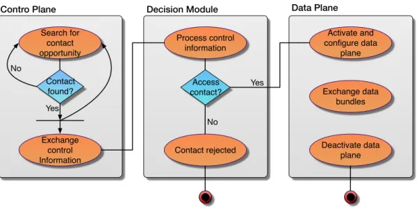
Figure 3.1 illustrates an activity diagram of a mobile node, which repre-sents a workflow of stepwise activities and actions describing control plane and data plane interaction, coordinated by the decision module. This activity dia-gram is equal for all network nodes, and represents the concept of control plane and data plane separation with out-of-band signaling. Each network node au-tonomously manages its control plane and data plane link connections. Nodes are always searching for new contact opportunities, using their control plane link connection (low-power, low bandwidth, long-range), which is always ac-tive. A decision module is responsible for processing the control information exchanged at a new contact opportunity to decide whether to accept the con-tact, and for determining the amount of time that lasts the contact [27]. Then, the data plane link connection (high-power, high bandwidth, short-range) is ac-tivated, and remains in this state only during the estimated period of time that lasts the contact. Nodes use their data plane link to exchange data bundles. The BSC layer executes the control plane functions, such as signaling messages exchange, resources reservation (at the data plane), and routing. The BAD layer executes the data plane functions that deal with data bundles. These functions include storage management, queuing and scheduling, and traffic classification, among others.
The presented testbed was created for a laboratory environment. Its de-sign is modular with well-defined interfaces between the hardware and software components. This enables updating different hardware/software components with minimal impacts on the others. Another important aspect is that inter-ested researchers can easily reproduce this testbed, as the needed hardware to perform it is not expensive, it is easily available, and easy to set up. Further-more, the software is hardware device independent as much as possible and it has been developed in such a way as to adapt itself to a future deployment in a
Research Methodology Contro Plane Search for contact opportunity Contact found? Exchange control Information Decision Module Process control information Access contact? Contact rejected Data Plane Activate and configure data plane Deactivate data plane Exchange data bundles Yes No Yes No
Figure 3.1: UML activity diagram of a mobile node, describing the control plane and data plane interaction, coordinated by decision module
real-world testbed with minimum efforts.
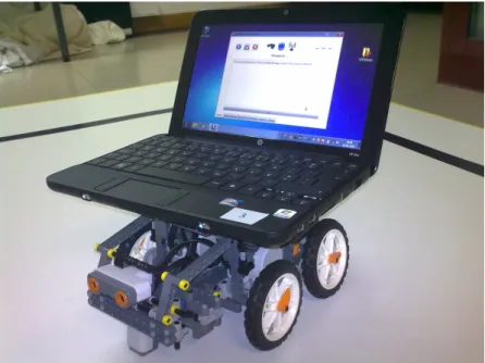
The testbed considers three types of network nodes previously described. Desktop and laptop computers are used to emulate terminal nodes and relay nodes. Mobile nodes (e.g., vehicles) are emulated through LEGO MINDSTORMS NXT robotic cars [39] and a netbook computer. A mobile node is shown in Figure 3.2. As may be seen, each robotic car carries a netbook for having processing, networking, and storage capabilities. LEGO NXT robots are programmed with several mobility models (e.g., random movement across roads or bus move-ment), allowing performance evaluation studies under different movement pat-terns. All network nodes support Bluetooth [40] and IEEE 802.11 b/g [41] tech-nologies. These technologies are used to support the VDTN out-of-band signaling with the separation between control and data planes. Bluetooth connection is used to exchange signaling information (control plane), whereas IEEE 802.11 b/g is used for data bundles exchange (data plane). Figure 3.3 shows some interac-tions between mobile nodes, terminal nodes, and relay nodes.
Several software modules were created in C# programming language and deployed in the network nodes. They were developed using the. NET Framework for running in the desktops, laptops, and netbooks with Windows 7 operating system. The software modules implement the above-described VDTN architec-ture principles. They also provide functionalities to emulate network resource constraints (e.g., energy, storage, bandwidth, range), to emulate different op-eration conditions, and to emulate network applications with different traffic characteristics and different ”quality of service” requirements. In addition, the software modules provide management tools and advanced statistics reports.
Research Methodology
Figure 3.2: A mobile node created with a Lego MINDSTORMS NXT robot and a coupled netbook.
Figure 3.3: Illustration of VDTN nodes interaction: (a) a mobile and a terminal node establishing contact, (b) a mobile and a relay node establishing contact and (c) two mobile nodes establishing contact.
For example, it is possible to collect statistical data about the delivery ratio and average delay, the bundles drop ratio, the number of contacts per hour, the average contact time, and the historic of nodes that have stored-carried-and-forwarded each delivered bundle.
The class diagram shown in Figure 3.4 details the main classes of the software developed for the testbed. This comprehensive diagram provides an overview of the virtualization of the VDTN network model. Class attributes
Research Methodology
and methods were omitted to improve the diagram readability. The main class application, called VDTNHost, interacts with the classes responsible for data exchange, which is the ControlPlaneLink that is used for signaling messages ex-change, and the DataPlaneLink that is used for data bundles exchange. VDTNHost class also interacts with the classes that implement control plane (BSC) and data plane (BAD) separation. As expected, both Signaling and Routing classes are con-nected to BSC class. The Signaling class is responsible for generating and pro-cessing signaling messages. The Routing class generates and processes routing protocols information, and selects which bundles should be exchanged, based on the routing protocol under use. The BAD class interacts with the BufferManage-ment class that is responsible for applying a drop policy when buffer congestion occurs, and with the Scheduling class that applies a scheduling policy to de-termine the order by which bundles should be sent at a contact opportunity. The BAD class also is connected with the Classification class that implements the functions for traffic differentiation [42], and with the De/ Aggregation class that is responsible for forming data bundles by aggregating IP packets, according to a bundle assembly algorithm.
VDNTHost Buffer BSC BAD Signaling Routing Epidemic Spray and Wait … Buffer Management Forwarding De/Aggregation Classification Scheduling … DropTail DropHead … LIFO FIFO ControlPlane Link DataPlane Link 1 1 1 1 1 1 1 1 1 1 1 1 1 1 1 1 1 1 1
Figure 3.4: UML class diagram illustrating the main classes andimportant relationships in VDTN testbed
3.4
Summary
In this chapter, the design, construction of aggregation and de-aggregation mechanisms for VDTNs was discussed. These mechanisms are deployed on a laboratory testbed, called VDTN@Lab. In the literature several testbeds are used as a research method and have been developed to support the deployment and evaluation of architectures and protocols in vehicular networks. These
Research Methodology
testbeds were presented in Section 3.2. The Section 3.3 described the labo-ratory testbed, called VDTN@Lab where the designed aggregation approaches were deployed.
Performance Evaluation and demonstration
Chapter 4
Performance Evaluation and Demonstration
4.1
Introduction
This chapter focuses on the performance evaluation of VDTN aggregation mechanisms described in Chapter 2. The study was conducted through exper-imentation, using VDTN@Lab laboratory testbed that was described in Chapter 3. In the related literature there are several studies about DTNs and VDTNs net-works, namely, in [43] . Thi study may be considered as a basis for setting up network scenarios for performance assessment and comparison purposes.
The remainder of this chapter is organized as follows. Section 4.2 shows the networks scenarios used for the testbed experiments, and The impact of ag-gregation schems on the performance of VDTN networks is presented in Section 4.3.
4.2
Network Scenario
The scenario that was set up to conduct experiments on the VDTN testbed has a dimension of 36,5m2 and is shown in Figure 4.1. It consists in three fixed terminal nodes, four mobile nodes, and two relay nodes. Terminal nodes are placed at different points (edges) of the laboratory. Parallel with a study based on a testbed composed by real vehicles [44], and assuming a scale of 1:50 (1 min the laboratory testbed represents 50 min a real scenario), Mobile node 1 moves at 48 km/h, mobile node 2 at 40 km/h, mobile 3 at 36 km/h, and mobile node 4 at 24 km/h. Relay nodes are placed on roads intersections. Figure 7 shows photos of the VDTN laboratory testbed and some of the above-presented nodes. At the very beginning, all nodes have their buffers empty and are ready to receive and transfer bundles. Bundles have random source and destination terminal nodes and are generated assuming different aggregation mechanisms. When a bundle reaches its final destination it is marked as delivered. For testbed experiments, the bundle’s TTL changes between 5, 10, 15, and 20 min. It is assumed a fully cooperative opportunistic environment and each experiment has a duration of 1 h.
Performance Evaluation and demonstration
Figure 4.1: VDTN@Lab laboratory testbed scenario.
4.3
Performance Evaluation of Aggregation and Deaggregation
Mechanisms
4.3.1 Aggregation Algorithms
The aggregation algorithms have been evaluated over different input traf-fic conditions. Input traftraf-fic (datagrams) is created in the same application of terminal nodes and this application generates different types of traffic load (considering low, medium, and high). In such a case of a low traffic load, data-grams are created in a time interval of 1 up to 3 seconds; medium traffic load in the time interval of the 0.5 up to 1.5 seconds, and the high traffic load in the time interval of the 0.25 up to 0.75 seconds. These datagrams have random des-tination terminal nodes and its size is uniformly distributed and average length is 1250 Bytes. Data bundles have a time- to-live (TTL) fixed on 10 minutes. The timer and threshold values changes among different testbed experiments in order to evaluate the performance of bundle assembly.
For the timer-base algorithm the timer value is fixed on 120 seconds. Threshold-based algorithm threshold value is equal to 150 datagrams. Hybrid algorithm has both the timer and threshold values.
Every result show that every algorithm performance had better results with a proper network traffic algorithm. This because it was proved in the literature as good simulators of real network traffic and real internet usage.
Performance Evaluation and demonstration 0 50 100 150 200 250 300 350
Low Medium High
Avergage Aggrega(on Delay (sec) Traffic Load Time-‐Based Threshold-‐ Based Hybrid
Figure 4.2: Performance evaluation of proposed algorithms: Average aggregation delay as function of traffic load for different traffic loads (low , medium, and high).
(easy, medium, and high). For this study is used all aggregation algorithms above described. As may be seen, the Hybrid Algorithm presents the best results and gains of approximately 14, 20, and 225 (for low, medium, and high traffic loads) when compared to the Timer-based Algorithm. Comparing Hybrid Algorithm with the Threshold-based Algorithm, it presents gains of approximately 216, 6, and 7 seconds. Figure 4.2 confirms the theoretical behavior of these algorithms. Under low traffic load, timer-based algorithms are the best technique for bun-dle generation and, under high traffic level, threshold-based algorithms have a better behavior for improvement of VDTN bundle aggregation. Thus, it is nat-ural that Hybrid Algorithm, based on the two approaches, is the most efficient aggregation algorithm.
4.3.2 QoS Support Schemes
For the QoS schemes, we intent to prove that the QoS requirements of in-coming packets not change with bundle assembly. For this, a uniform distribu-tion of classes number was calculated. Equadistribu-tion (4.1) one possible distribudistribu-tion. Value p(i) represent the percentage of packets with class i. p(j) represent the percentages of previous classes that i≥ j ≤ n − 2.
p(i) = (100− (
∑n−1
j p(j))
i + 2 )× 2 (4.1)
prior-Performance Evaluation and demonstration 0" 10" 20" 30" 40" 50" 60" 70" 80"
Single"4:4" Composite"4:4" Sigle"4:2" Composite"4:2"
%"
Priority"0" Priority"1" Priority"2" Priority"3"
Figure 4.3: Performance evaluation of proposed algorithms: Distribution of bundle priorities after aggregation algorithms.
ity), Class 1, Class 2, and Class 3 (less priority). By (4.1), the distribution is 40%, 30%, 20%, and 10% respectively. We assumed that incoming packets arrival at the terminal node according to a Poisson process and average packet length is 1250Bytes. The four schemes above described has been tested: Single-Class Bundle with N = M = 4 (Single 4:4), Composite-Class Bundle with N = M = 4 (Composite 4:4), Single-Class Bundle with N = 4 and M = 2 (Single 4:2), and Composite-Class Bundle with N = 4 and M = 2 (Composite 4:2).
Figure 4.3 shown the distribution, in percentage, of priorities applied in VDTN network core. The gray lines represent the optimal values of these per-centages given by (4.1). In general, four schemes produces an acceptable dis-tribution of priorities, with the Composite schemes having better results. This because the aggregation of different classes in a single bundle.
4.3.3 Network Performance Analysis
The network performance of routing protocols using the proposed aggre-gation algorithms is analyzed in this subsection. This sub-section studies the performance evaluation of the above-presented VDTN testbed using Epidemic, Spray and Wait, and PRoPHET routing protocols. Based on previous results, three aggregations algorithms are considered to perform this analysis. Figure 4.4 shows the bundle average delay when pure timer-based aggregation algo-rithms are used. In average, bundle delay shown in Figure 4.5 is used threshold-based algorithms. In the last figure (Figure 4.6)), the evaluation is performed for the hybrid aggregation approach.
As shown, the network performance is very similar with different aggre-gation algorithms because the aggreaggre-gation algorithms not influence the
perfor-Performance Evaluation and demonstration 100 200 300 400 500 600 700
Low Medium High
Bu n d le A ve rage D el ay (s ec ) Traffic Load Epidemic Spray and Wait PRoPHET
Figure 4.4: Bundle average delay as function of traffic load for timer-based algorithm.
100 200 300 400 500 600 700
Low Medium High
Bu n d le A ve rage D el ay (s ec ) Traffic Load Epidemic Spray and Wait PRoPHET
Figure 4.5: Bundle average delay as function of traffic load for threshold-based algorithm.
Performance Evaluation and demonstration
mance of routing protocols. However, small differences can be observed on the overall network performance. Comparing the three figures, one can ob-serve that timer-based algorithms perform better under low traffic load and the threshold- based approach perform better under high traffic load. The Hy-brid Algorithm combines the advantages of both. In terms of routing protocols, Spray and Wait performs better along all the studies and PRoPHET presents the worst network performance. When traffic load increases, this different behavior is more significant.
4.4
Summary
A performance analysis of aggregation mechanisms for VDTNs was pre-sented. The networks scenarios were described in Section 4.2, presenting it main features, such as, mobile nodes mobility patterns, datagrams creation in-terval, bundle TTL. Section 4.3 was focused on the performance of aggregation protocols when enforced on the VDTN@Lab testbed. This study was conducted following several approaches. First, a performance assessment of aggregation protocols is presented. With different traffic loads, the proposed aggregation approaches were evaluated. Then, different classes of datagrams were created to evaluate the performance of the QoS support framework. Finally, a gener-alized experiment using all nodes of VDTN testbed was created to evaluate de impact of aggregation in network performance.