RADIATION SCIENCES
07-02B (2019) 01-15ISSN: 2319-0612 Accepted: 2019-02-19
BJRS
Simulation of Mechanical Behavior of Fuel Pellets With
Different Geometries
Amanda Abati Aguiar¹
¹Navy Technological Center
ABSTRACT
Typical Pressurized Water Reactors (PWR) fuel rods are manufactured using zirconium-based alloys as clad-ding and slightly enriched UO2 sintered pellets as fuel. However, in the last years efforts have been made to
de-velop Accident Tolerant Fuels (ATF) focusing mainly in new materials to replace the cladding in order to avoid the exothermic reaction with steam experienced by zirconium-based alloys under accident conditions as observed during the Fukushima Daiichi accident. In this sense, iron-based alloys appear as a possibility to replace conven-tional zirconium-based alloys, and the effect of the pellet geometry in the performance of iron-based alloys fuel rods shall be investigated. The fuel pellet geometry experiences changes due to irradiation can promote early gap closure, mechanical loadings to the cladding and/or bamboo effects due to the combination of loads and irradia-tion creep, and all these effects depend also on the cladding properties. The objective of this paper was to address the influence of geometric parameters in the fuel pellet behavior of a stainless steel fuel rod by means of struc-tural mechanical analysis using the well-known ANSYS software. The parameters evaluated in this paper con-sidered fuel pellet with and without chamfer and dish. The data related to the fuel pellet performance under ir-radiation were obtained using a modified version of the FRAPCON code considering stainless steel as cladding. Results obtained from mechanical evaluation considering the effects through the responses of the axial, radial, plastic deformations, and resulting tensions were evaluated.
1. INTRODUCTION
Nowadays, efforts to improve the fuel system under accident condition became main stream of research and development in the fuel design area, especially the use of new alloys to overcome some of well-known existing problem with zirconium-based alloys cladding. Under this context, this work address the fuel pellet geometric design using iron-based alloy as cladding material, specifically stainless steel 348. This material presents better properties compared to zirconium-based alloys, such as high thermal conductivity, and high thermal expansion. Those material properties combined to adequate fuel pellet geometry can improve the fuel system performance under normal and accident condition.
During the reactor operation, the geometry of the UO2 fuel pellet changes in relation to its original
shape due to the following main effects: thermal expansion that includes distortions in the original form, formation of cracks, and relocation of pellets fragments; and swelling and densification that is a phenomenon associated with burnup and the effect of restructuring in the pellet.
The effects of thermal expansion are proportional to the reactor power and act directly from the beginning of the reactor operation. When the reactor is gradually brought to full power, the cylindrically shaped pellets expand thermally, distorting in the shape of an "hourglass" with convex contact faces. For a relatively low power level, the thermal stresses in the tangential direction generate radial cracks which can expand and promote mechanical interactions with the inner surface of the cladding causing Pellet Cladding Mechanical Interaction (PCMI). During power variations (cycling conditions) occur the relocation of the fuel pellet fragments associated with the effects above described. Relocation also can contribute to reduce the gap between the fuel and the cladding.
Changes in the fuel morphology caused due to high temperature level thermal gradient are characteristic of the fuel "restructuring" phenomena subjected to high burnup. The “restructuring” phenomena involves the equiaxial growth of grains in the intermediate region of the fuel, pore migration, and fission gas bubbles leading to the appearance of columnar grains and voids. The direct result of these interactions is the "redistribution" of fuel to the periphery region.
At high burnup conditions, the swelling of the pellet may predominate over densification and in as-sociation with the "relocation" and "restructuring" effects can contribute to increase the fuel pellet diameter when compared to thermal expansion.
2. MATERIALS AND METHODS
2.1. Geometry of the Fuel PelletInitially, three different fuel pellet geometries were evaluated:
1- fuel pellet with flat contact faces (without dish, edges or chamfers); 2- fuel pellet with dish; and
3- fuel pellet with dish and chamfer.
The dimensions adopted to perform the evaluation were based on regular dimensions of standard western PWR.
2.2. Computacional Tools
The verification and analysis of the variation of the most suitable geometry for the fuel pellet were carried out considering basically two computational tools: a modified fuel performance code based on FRAPCON [1], and ANSYS [2] mechanical-structural analysis computational code.
FRAPCON is an analytical computational code for the calculation of nuclear fuel performance for Light Water Reactors (LWR) with cylindrical fuel rod. The FRAPCON computational code is recommended when power and operating conditions change slowly allowing the steady-state condition to be applied [1]. The code was initially developed in FORTRAN language in a modular way to consider only zirconium-based alloys as cladding material, however the modularity allows changing the subroutines associated with the cladding material, thus adapting the code to evaluate the performance of different cladding materials [3].
The changes in the original FRAPCON computational code subroutines were performed to consider the stainless steel 348 as cladding. The modified version of the FRAPCON computational code, called IPEN-CNEN/SS [4], was used to determine the spatial distribution of the temperature along of radial direction of the fuel pellet with different geometries considering a given reactor operating condition.
The ANSYS computational code is a widely known tool used to perform multi-physical simulations using finite element method and finite volume method. This code was used to establish the strain and
deformations resulting from the temperature distribution previously obtained using the IPEN-CNEN/SS code. The tensile and strain distribution calculations were obtained considering the three different geometries of the fuel pellet.
The fuel rod performance was evaluated considering typical enrichment degree and burnup level of standard western PWR.
The data related to the fuel pellet required to perform the calculations with the ANSYS code are:
a) radial discretization (obtained from IPEN-CNEN/SS simulation); b) temperature distribution (obtained from IPEN-CNEN/SS simulation); c) Poisson's coefficient;
d) thermal expansion;
e) coefficient of thermal expansion; f) elasticity modulus; g) thermal conductivity; h) specific heat; i) enthalpy; j) density; and k) fracture stress.
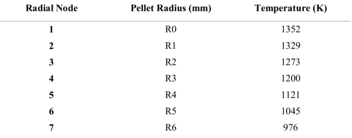
Table 1 shows the temperature distribution for 13 concentric rings (spatial intervals in the radial direction) obtained from IPEN-CNEN/SS code simulation.
Table 1: Fuel temperature input data provided to ANSYS code obtained by IPEN-CNEN/SS code.
Radial Node Pellet Radius (mm) Temperature (K)
1 R0 1352 2 R1 1329 3 R2 1273 4 R3 1200 5 R4 1121 6 R5 1045 7 R6 976
8 R7 917 9 R8 867 10 R9 828 11 R10 798 12 R11 777 13 R12 762 14 R13 754
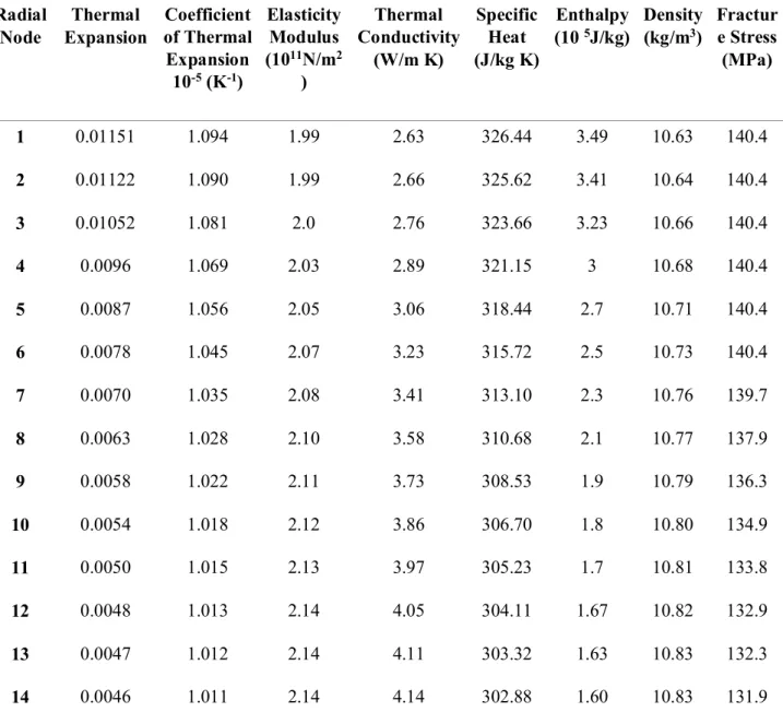
The thermal and mechanical properties of uranium dioxide pellets were extracted from references [5] and [6] and are shown in Table 2. The variables for the ANSYS code, such as thermal expansion, thermal expansion coefficient, modulus of elasticity, thermal conductivity, specific heat, enthalpy, density, and fracture stress were calculated as a function of the temperature distribution as shown in Table 1. The Poisson coefficient was taken as constant and equal to 0.316 [7].
The thermal conductivity, specific heat, enthalpy, and thermal expansion data obtained from literature [5] are presented below.
a) Thermal Conductivity:
(1)
K = thermal conductivity (W/m K); T = temperature (K);
Bu = burnup (2.535Gwd / MTU - output data from IPEN-CNEN/SS code); f (Bu) = effects of fission products in the matrix;
g (Bu) = irradiation defects = 0.038 * Bu0.28;
h (T) = annealing temperature dependent on irradiation defects (1/1 + 396 exp (-Q / T)); Q = temperature dependent parameters ("Q / R") = 6,380 K;
A = 0.0452 m K/W; B = 2.46 * 10-4 m K/W/K;
E = 3.5 * 109 WK/m; F = 16,361 K. b) Specific Heat: (2) c) Enthalpy: (3)
FCP = specific heat capacity (J/kg K); FENTHL = fuel enthalpy (J/kg); K1 constant = 296.7;
K2 constant = 2.43 * 10-2;
K3 constant = 8.745 * 107;
θ = Einstein temperature (K) = 535.285;
ED = activation energy for Frenkel defects (J / mol) = 1.577 * 105;
T = temperature (K);
R = universal constant of gases (8.3143 J/mol K); Y = oxygen / metal ratio.
(4)
ΔL / L0 = linear deformation caused by thermal expansion (0 with temperature of 300K), dimensionless;
T = temperature (K); K1 constant = 1 * 10-5;
K2 constant = 3 * 10-3;
K3 constant = 4 * 10-2;
ED = defect formation energy (J) = 6.9 * 10-20;
K = Boltzmann's constant = 1.38 * 10-23J / K;
The density, thermal expansion coefficient and modulus of elasticity were based on reference [6].
e) Density:
ρ = ρ0 (1- 3εUO2) (5)
ρ = theoretical density of UO2 (kg/m3);
ρ0 = density at room temperature of UO2 = 10.980 kg/m3;
εUO2 = linear deformation caused by thermal expansion (0 with temperature of 300 K).
f) Thermal Expansion Coefficient:
ΔL / L0 = linear deformation caused by thermal expansion; K1 = coefficient of linear expansion (K-1);
T0 = reference temperature (K); T = temperature (K). g) Modulus of Elasticity: E = 23.34 * 1010 (1-1.0915 * 10-4T) (1-2.752 P) (7) E = Young's modulus of UO2 (N / m2); T = temperature (K);
P = porosity (1-fuel density).
The fracture stress is based on the ffracs subroutine existing in the material data [6] used by the IPEN-CNEN/SS computer code, the equation adopted is:
σ f=a
(
1−b(
1−f)
)
0,5exp(
−q 1. 987•T)
(8)
σf = fracture stress of the UO2 pellet, as a function of temperature and fractional density (Pa);
a = 1.7 * 108;
b = 2.62; q = 380;
T = temperature (K);
f = fractional density of the UO2 pellet (ratio of current density to theoretical density);
Table 2: UO2 input data provided to ANSYS code obtained by IPEN-CNEN/SS code. Radial Node Thermal Expansion Coefficient of Thermal Expansion 10-5 (K-1) Elasticity Modulus (1011N/m2 ) Thermal Conductivity (W/m K) Specific Heat (J/kg K) Enthalpy (10 5J/kg) Density (kg/m3) Fractur e Stress (MPa) 1 0.01151 1.094 1.99 2.63 326.44 3.49 10.63 140.4 2 0.01122 1.090 1.99 2.66 325.62 3.41 10.64 140.4 3 0.01052 1.081 2.0 2.76 323.66 3.23 10.66 140.4 4 0.0096 1.069 2.03 2.89 321.15 3 10.68 140.4 5 0.0087 1.056 2.05 3.06 318.44 2.7 10.71 140.4 6 0.0078 1.045 2.07 3.23 315.72 2.5 10.73 140.4 7 0.0070 1.035 2.08 3.41 313.10 2.3 10.76 139.7 8 0.0063 1.028 2.10 3.58 310.68 2.1 10.77 137.9 9 0.0058 1.022 2.11 3.73 308.53 1.9 10.79 136.3 10 0.0054 1.018 2.12 3.86 306.70 1.8 10.80 134.9 11 0.0050 1.015 2.13 3.97 305.23 1.7 10.81 133.8 12 0.0048 1.013 2.14 4.05 304.11 1.67 10.82 132.9 13 0.0047 1.012 2.14 4.11 303.32 1.63 10.83 132.3 14 0.0046 1.011 2.14 4.14 302.88 1.60 10.83 131.9
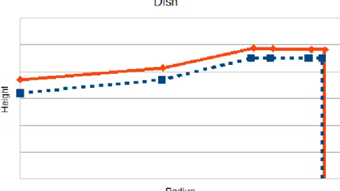
Figs. 1 to 3 show the axial and radial displacement (expansion) profiles of the three configurations of typical PWR fuel pellet estimated by the ANSYS code.
The greater axial expansion was obtained for the configuration of the pellet with flat faces. The axial expansions for the dish, and dish and chamfer configurations are similar.
For the radial expansion, the differences observed between the different geometries of the pellet are in the range of thousandths of millimeters.
Therefore, the axial and radial expansions are smaller for the pellet configuration containing the dish and chamfer.
Figs. 4 to 6 illustrate a 3D view with axial and radial expansions obtained by the ANSYS code for each studied pellet geometry. These illustrations corroborate with the graphics below.
The configuration of the fuel pellet with the flat surface has maximum axial expansion of 0.0513 mm and radial expansion at the end of the pellet of 0.0375 mm. For the pellet with dish, the maximum axial expansion is 0.0503 mm and the radial expansion is 0.0377 mm. For the fuel pellet with dish and chamfer configuration, the greatest axial expansion is 0.0503 mm, the radial expansion occurring at the chamfer of the pellet with 0.0362 mm. It is observed that this last pellet configuration is the one with the smallest radial deformation.
Figure 1: Profile of the fuel pellet with and without thermal gradient in the configuration with flat
Figure 2: Profile of the fuel pellet with and without thermal gradient in dish configuration
Figure 3: Profile of the fuel pellet with and without thermal gradient in configuration with
Figure 4: Illustration of the maximum deformations in the fuel pellet with configuration of
flat faces: a) axial, and b) radial
Figur e 5: Illustr ation of the maxi mum defor matio ns in the fuel pellet with configuration of dish: a) axial, and b) radial
Figur e 6: Illustr ation of the maxi mum defor matio ns in the fuel pellet with configuration of dish and chamfer: a) axial, and b) radial
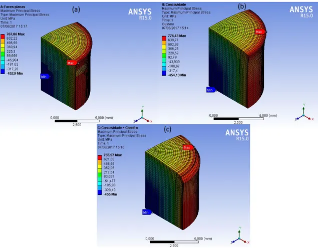
The strain s due to therm al expan sion obtained with the ANSYS code are shown in Fig. 7.
The maximum strain is located at the end (external parts) of the pellet, and for each configuration, the strain is distributed differently. When the pellet has a chamfer, the tension is distributed in the chamfer, increasing the specific surface area, decreasing the maximum tension in this configuration. The fracture stress of the fuel pellet at the temperature of 754 K is 131.9 MPa as shown in Table 1 and 2, and it can be seen from Fig. 7 that for all the configurations of the pellet, the tensions obtained from the ANSYS code exceed the fracture stress of the material, causing cracks.
Figure 7: Principal strain generated in the three configurations of the fuel pellet: (a) flat
faces, (b) dish, and (c) dish and chamfer.
4. CONCLUSION
According to the obtained results, considering stainless steel 348 as cladding and UO2 fuel pellet
and chamfer configuration. This pellet configuration contributes to the reduction of the occurrence of the circumferential ripples effect on the cladding ("bamboo") of the fuel rods and also prevents the formation of fragments (chips) in the pellet. The fuel pellet with appropriate size of dish and chamfer shall present a better performance during the irradiation and contribute to minimize the occurrence of PCMI effects during the irradiation even considering the higher thermal expansion experienced by stainless steel compared to zirconium-based alloys.
The maximum strain for the three geometries of the fuel pellet is located in the external parts, being superior to the fracture stress, about 131 MPa, promoting cracks in the three configurations of the pellet as expected.
5. ACKNOWLEDGMENT
The authors are grateful for the technical support provided by IPEN-CNEN/SP, CTMSP and USP.
REFERENCES
1. “FRAPCON-3.5: A Computer Code for the Calculation of Steady-State, Thermal-Mechanical Behavior of Oxide Fuel Rods for High Burnup, NUREG/CR-7022, Vol. 1, Rev. 1.
2. ANSYS, www.ansys.com/products, 2017.
3. STRASSE, A., et. al. An Evaluation of Stainless Steel Cladding for Use in Current Design LWRS. EPRI – NP--2642, Palo Alto, December, 1982.
4. ABE. A.; GIOVEDI, C., et.al. Revisiting Stainless Steel as PWR Fuel Rod Cladding after Fukushima Daiichi Accident. Journal of Energy and Power Engineering 8, p. 973-980, 2014.
5. LUSCHER. W. G., et.al. Material Property Correlations: Comparisons between FRAPCON -3.5, FRAPTRAN-1.5, and MATPRO. NUREG/CR-7024, Rev. 01, 2014.
6. ALLISON. C. M., et.al. SCDAP / RELAP5/ MOD 3.1. Code Manual Volume IV: MATPRO- A Library of Materials Properties for Light -Water -Reactor Accident Analysis. Nov.,1993.
7. DONALD. L. H., et. al. MATPRO - Version 11: A Handbook of Materials Properties for use in the Analysis of Light Water Reactor Fuel Rod Behavior. NUREG/CR-0497, 1979.