UNIVERSIDADE DA BEIRA INTERIOR
Engenharia
Energy Storage Systems and Grid Code
Requirements for Large-Scale Renewables
Integration in Insular Grids
Eduardo Manuel Godinho Rodrigues
Tese para obtenção do Grau de Doutor em
Engenharia Eletrotécnica e de Computadores
(3.º ciclo de estudos)
Orientador: Prof. Doutor João Paulo da Silva Catalão Coorientador: Prof. Doutor João Carlos de Oliveira Matias
iii
This thesis was supported by FEDER funds (European Union) through COMPETE and by Portuguese funds through FCT, under Projects FCOMP-01-0124-FEDER-020282 (Ref. PTDC/EEA-EEL/118519/2010) and UID/CEC/50021/2013. Also, the research leading to these results has received funding from the EU 7th Framework Programme FP7/2007-2013 under grant agreement no. 309048, project SiNGULAR.
v
Dedicatory
I dedicate this thesis to my family, who with love, dedication and effort, always believed in my capabilities, supporting me unconditionally. Without them, nothing of this would be possible. Thank you very much.
vii
Acknowledgement
It is not always easy to find the appropriate words to express how much we are thankful to all the persons that somehow contributed to this work. Nevertheless, I would like to express my thanks to all those people who made this thesis possible and an unforgettable experience for me.
The first words have to be directed to my supervisors, Prof. João Catalão and Prof. João Matias. I am deeply indebted to Prof. João Catalão for giving me a research direction and for all the help, ideas, comments and constant encouragement throughout this work. I also thank Prof. João Matias for his enthusiasm, inspiring to all of us.
I would like to thank to my colleagues at Sustainable Energy Systems laboratory of UBI, for their friendship, support and valuable discussions about the topics of this work. Many thanks to all of them, who were able to create a friendly atmosphere for the development of this work. I would like to thank also to my colleagues at ALSTOM, namely Roberto Bove, Gianfranco Guidati, Efthalia Skoufa and Vipluv Aga, to SMARTWATT, in the name of Prof. Cláudio Monteiro, to EDA, for Engº Filipe Mendonça, and to ITC, for Daniel and Salvador.
To all those who contributed directly or indirectly to the development this dissertation, I also wish to express my deepest thanks.
viii
Resumo
Esta tese aborda a temática dos sistemas de armazenamento de energia visando o aumento da penetração de energias renováveis em sistemas insulares. Uma visão geral é apresentada acerca da gestão do armazenamento de energia, ferramentas de previsão e soluções do lado da procura de energia, comparando a utilização estratégica do armazenamento e outras estratégias concorrentes. É dada ênfase aos sistemas de armazenamento de energia em ilhas, como uma nova contribuição no estado da arte, abordando as suas necessidades específicas, as tecnologias mais adequadas e os projetos existentes e em funcionamento a nível mundial. Vários casos de estudos reais são apresentados e discutidos em detalhe. Parâmetros de projeto de baterias de chumbo-ácido são avaliados para aplicações de armazenamento de energia em redes insulares, comparando diferentes modelos de baterias. O efeito de redução do potencial de desperdício de energia do vento, recorrendo ao armazenamento de energia, também é perscrutado. As especificidades subjacentes aos códigos de rede para a integração em larga escala de energias renováveis são discutidas em contexto insular, sendo outra nova contribuição no estado da arte. As tendências atuais na elaboração de códigos de rede, no sentido de uma melhor integração da geração distribuída renovável em sistemas insulares, são abordadas. Finalmente, é estudada a modelação e as estratégias de controlo com sistemas de armazenamento de energia. Uma metodologia de gestão de energia inovadora é apresentada para a exploração de curto prazo de sistemas insulares com baterias de fluxo Vanádio Redox.
Palavras-Chave
x
Abstract
This thesis addresses the topic of energy storage systems supporting increased penetration of renewables in insular systems. An overview of energy storage management, forecasting tools and demand side solutions is carried out, comparing the strategic utilization of storage and other competing strategies. Particular emphasis is given to energy storage systems on islands, as a new contribution to earlier studies, addressing their particular requirements, the most appropriate technologies and existing operating projects throughout the world. Several real-world case studies are presented and discussed in detail. Lead-acid battery design parameters are assessed for energy storage applications on insular grids, comparing different battery models. The wind curtailment mitigation effect by means of energy storage resources is also explored. Grid code requirements for large-scale integration of renewables are discussed in an island context, as another new contribution to earlier studies. The current trends on grid code formulation, towards an improved integration of distributed renewable resources in island systems, are addressed. Finally, modeling and control strategies with energy storage systems are addressed. An innovative energy management technique to be used in the day-ahead scheduling of insular systems with Vanadium Redox Flow battery is presented.
Keywords
xii
Table of Contents
Dedicatory... v Acknowledgement ... vii Resumo ... viii Palavras-Chave ... viii Abstract... x Keywords ... xTable of Contents ... xii
Figures List ...xvi
Tables List ... xx Acronyms ... xxii Nomenclature ... xxvi 1. Introduction ... 1 1.1. Framework ... 1 1.2. Motivation ... 4 1.3. Thesis Structure ... 7
2. Overview of Storage Management, Forecasting Tools and Demand Side Solutions ... 9
2.1. Energy Storage Systems and Management Methods ... 9
2.2. Tools for ESS Management ... 20
2.3. Forecasting Tools ... 25
2.3.1. Role in insular energy systems ... 25
2.3.2. Wind Power Forecasting ... 25
2.3.3. Load Forecasting ... 29
2.4. Demand Side Management: Economic Aspects and Management Options... 34
2.4.1. Description of Demand Side Management ... 34
2.4.2. The six levers of DSM ... 35
xiii
2.4.4. Role of DSM in a smart grid ... 38
2.4.5. Economic impact measures for DSM solutions ... 40
2.4.6. Generation management ... 44
2.4.7. Impacts of RES penetration ... 46
2.4.8. Grid reinforcement ... 47
2.5. EES and Other Competing Strategies ... 48
2.5.1. Concepts ... 48
2.5.2. Strategic utilization of storage ... 50
2.5.3. Strategic utilization of DSM ... 51
2.5.4. Pertinence of storage ... 52
2.5.5. System operation... 54
2.5.7. Storage opportunities for the residential sector ... 56
3. ESS Supporting Increased Penetration of Renewables in Insular Systems ... 57
3.1. Introduction ... 57
3.2. Description of Energy Storage ... 60
3.2.1. Basic ES principles ... 60
3.2.2. Benefits of using ES ... 61
3.3. ES technologies: main assets and research issues ... 64
3.4. Global Markets Data and Key Features of ES Technologies ... 72
3.5. ES Applications... 73
3.6. ES on Islands... 76
3.6.1. Island specific requirements / challenges ... 76
3.6.2. ES technologies best suited for island grids ... 79
3.6.3. Economic ranking of ES technologies for islands by size ... 80
3.7. El Hierro Island Sustainable Energy System ... 84
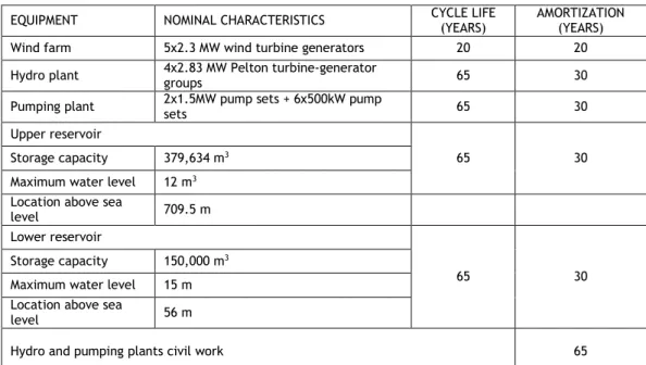
3.7.1. Hybrid hydro-wind electricity generation system ... 84
3.7.2. Investment analysis ... 85
3.7.3. Energy balance forecast during the economic life of the hydro-wind power plant 87 3.8. Conclusion ... 88
4. Insular Grid Case Studies ... 89
4.1. La Graciosa Island ... 89
4.2. Crete Island ... 96
4.3. Assessing Lead-Acid Battery Design Parameters for Energy Storage Applications on insular Grids: A Case Study of Crete and São Miguel Island ... 103
4.3.1. Introduction ... 103
xiv
4.3.3. Case study ... 108
4.3.4. Conclusion ... 114
4.4. Comparison of Battery Models for Energy Storage Applications on Insular Grids ... 114
4.4.1. Introduction ... 114
4.4.2. Battery modeling theory ... 115
4.4.3. Case study ... 123
4.4.4. Conclusion ... 127
5. Insular Grid Code Requirements for High RES Integration ... 129
5.1. Introduction ... 129
5.2. Current Status of Insular Energy Systems ... 131
5.3. Grid Code Requirements ... 133
5.3.1. Static requirements... 133
5.3.2. Dynamic grid support ... 142
5.4. Insular Smart Grid ... 147
5.4.1. Transmission/distribution system operators ... 149
5.4.2. Communication and supervisory control ... 150
5.5. Energy Storage as a Grid Code Requirement ... 150
5.6. Comparison of Island Grid Codes ... 152
5.7. Conclusions ... 154
6. Sizing and Control Strategy with Energy Storage Systems ... 155
6.1. Modelling and Sizing of NaS Battery Energy Storage System for Extending Wind Power Performance on Crete ... 155
6.1.1. Introduction ... 155
6.1.2. Crete power system ... 158
6.1.3. Modelling of electric energy storage system ... 162
6.1.4. Battery control ... 167
6.1.5. Simulation and Sizing of Battery Energy Storage System ... 169
6.1.6. Conclusions ... 177
6.2. Energy Storage System Management Based on Vanadium Redox Batteries ... 178
6.2.1. Introduction ... 178
6.2.2. Description of the power system ... 180
6.2.3. Day-ahead scheduling of power systems provided with storage devices ... 182
6.2.4. Case Study and results ... 185
6.2.5. Conclusions ... 188
6.3. New Schedule Management Approach of Energy Storage System in Insular Power System ... 188
xv
6.3.2. Insular power system modeling ... 191
6.3.3. Management of electrochemical energy storage systems ... 192
6.3.4. Case study and results ... 196
6.3.5. Conclusions ... 197
7. Conclusions ... 201
7.1. Energy Storage Systems Supporting Increased Penetration of Renewables in Insular Systems ... 201
7.2. Study of Lead-Acid Battery Design Parameters and Charging Sensibility Analysis ... 201
7.3. Characterization and comparison of four electrochemical battery types through performance indicators ... 202
7.4. Sizing of NaS Battery Energy Storage System ... 202
7.5. Energy Storage System Management Based on Vanadium Redox Batteries ... 203
7.6. Schedule Management Approach of Energy Storage System in Insular Power System . 203 7.7. Grid Code Compliance for High RES Integration ... 203
8. Guidelines for Future Contributions ... 205
9. Research Contributions Resulting from this Work ... 207
xvi
Figures List
Figure 1.1 World total primary energy supply from 1971 to 2012 by fuel [1]... ... 1
Figure 1.2 Installed wind and solar capacity by region: present and future [8] ... 3
Figure 2.1 A control hierarchy involving multiple ESS units ... 10
Figure 2.2 The structure of an insular network with RES integration [1] ... 11
Figure 2.3 ESS configurations [2] ... 12
Figure 2.4 Flowchart of operational strategy for a DG system [5] ... 15
Figure 2.5 Control scheme for BESS [6] ... 16
Figure 2.6 Block diagram of a basic smoothing control model [7] ... 16
Figure 2.7 Relation between the system target output and the SOC [7] ... 17
Figure 2.8 Regulation of the value of h(t) [7]... 18
Figure 2.9 General diagram of the calculation procedure for optimizing system management [11] ... 21
Figure 2.10 Time of use and dynamic price [105] ... 41
Figure 2.11 Abstraction of RES penetration level and degree of “smartness” ... 45
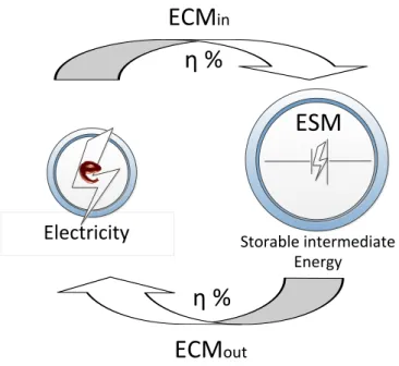
Figure 2.12 Cost versus flexibility comparison for energy metnods [110], [112], [113], [114] 49 Figure 3.1 Energy storage cycle – schematic representation ... 61
Figure 3.2 Thermal energy storage: simplified diagram ... 66
Figure 3.3 Regenerative hydrogen fuel cell ... 66
Figure 3.4 Energy storage using substitute natural gas: simplified diagram ... 69
Figure 3.5 Gravity power module energy storage (GPMES) working principle ... 71
Figure 3.6 Cryogenic energy storage: simplified diagram ... 71
Figure 3.7 Global ES capacity (MW) by technology (excluding PHES) ... 72
Figure 3.8 Electricity production comparison for islands by size [42] ... 81
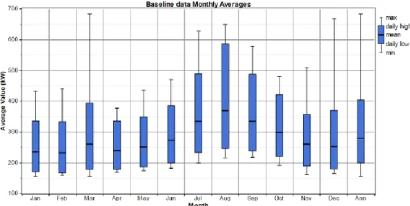
Figure 4.1 Mean, maximum and minimum power consumption per month in 2013 in La Graciosa. ... 90
Figure 4.2 Load profile during the period of maximum consumption in La Graciosa. ... 90
Figure 4.3 Power generation cost in Canary Islands in 2013. ... 91
Figure 4.4 Generation cost: daily profile in January 2013 (€/kWh). ... 91
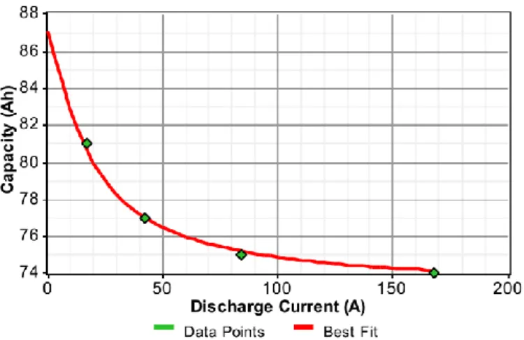
Figure 4.5 Experimental capacity curve of a Sinerion 24M battery cell. ... 92
Figure 4.6 Investment cost of PV system [2]. ... 93
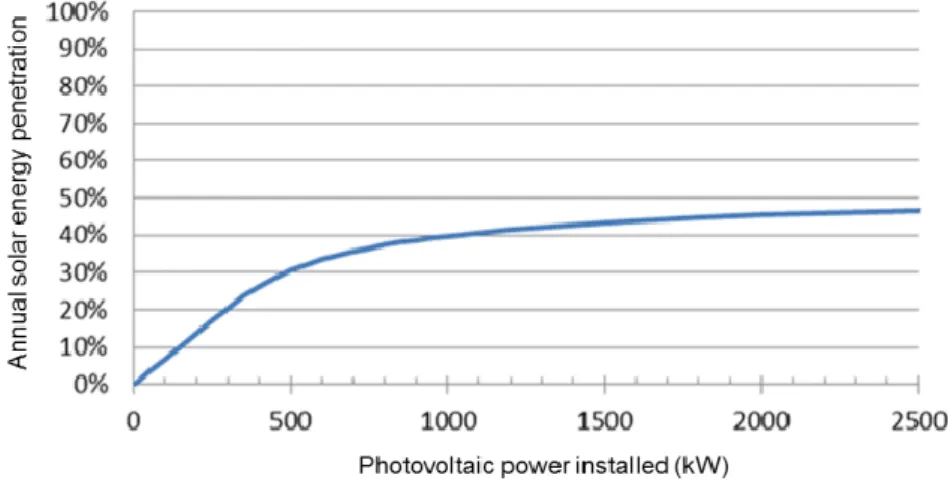
Figure 4.7 Annual solar energy penetration ratio in La Graciosa in function of PV power installed. ... 93
Figure 4.8 Hourly price for small consumers (<10 kW) for December 11, 2014 [3]. ... 94
xvii
Figure 4.10 Energy market price in Spain in 2013. ... 95
Figure 4.11 LCoE for different RES penetration with and without storage, comparing the optimal. ... 96
Figure 4.12 Schematic of the calculation process. ... 97
Figure 4.13 Graphical representation of the cost minimization problem. ... 98
Figure 4.14 Calculation of the minimum CAPEX for a storage discharge of 5 hours. ... 99
Figure 4.15 Calculation of the minimum CAPEX for a storage discharge of 5 hours. ... 99
Figure 4.16 Comparison for CAPEX for the system with and without storage for 5 hours storage discharge. ... 100
Figure 4.17 Comparison for CAPEX for the system with and without storage for 5 hours storage discharge. ... 100
Figure 4.18 Calculation of the minimum CAPEX for a storage discharge of 20 hours. ... 101
Figure 4.19 Minimum CAPEX. ... 101
Figure 4.20 Comparison for CAPEX for the system with and without storage for 5 hours storage discharge. ... 102
Figure 4.21 Comparison for CAPEX for the system with and without storage for 5 hours storage discharge. ... 102
Figure 4.22 Battery efficiency: State of charge (SOC) for charge. ... 107
Figure 4.23 São Miguel time series sample. ... 109
Figure 4.24 Battery capacity as percentage of original (São Miguel). ... 112
Figure 4.25 Battery capacity as percentage of original (Crete). ... 112
Figure 4.26 Mean number of cycles. ... 113
Figure 4.27 Maximum number of cycles per cell. ... 114
Figure 4.28 NiMH battery model. ... 119
Figure 4.29 Li-ion battery model. ... 120
Figure 4.30 Lead acid battery equivalent network. ... 122
Figure 4.31 Data sample of renewable energy sources from São Miguel. ... 123
Figure 4.32 São Miguel Island: Storage capability. ... 125
Figure 4.33 São Miguel Island: Demand capability. ... 125
Figure 4.34 Crete: Storage capability. ... 126
Figure 4.35 Crete: Demand capability. ... 126
Figure 4.36 Crete: Demand capability. ... 127
Figure 4.37 Storage capability versus number of strings. ... 128
Figure 5.1 The operating area of voltage and frequency for French insular grid codes. ... 134
Figure 5.2 Power-frequency response required by mature grid codes in mainland networks. ... 137
Figure 5.3 Danish P-Q interconnection requirements for wind power plants. ... 138
Figure 5.4 Reactive power capability requirements for the German case. ... 139
xviii
Figure 5.6 The frequency response requirement applied to French isolated grids. ... 142
Figure 5.7 FRT interconnection requirements for German and Danish codes. ... 144
Figure 5.8 FRT curve examples required in European insular power systems. ... 145
Figure 5.9 Comparison of reactive power requirements during a voltage disturbance. ... 147
Figure 5.10 Typical Information flux between VPP Control Center and DG units. ... 150
Figure 5.11 Energy storage technologies as a function of discharge time [80] [81] [82]. ... 152
Figure 6.1 Time series of Crete power grid: (a) Load demand and thermal power generation; (b) Gross and net wind power generation. ... 159
Figure 6.2 Comparison of time series based on maximum, minimum and average values: (a) Demand; (b) Theoretical wind power generation. ... 160
Figure 6.3 Monthly generation levels for conventional and non-conventional plants versus consumption. ... 161
Figure 6.4 Wind curtailment evolution for different periods of the day. ... 162
Figure 6.5 Open circuit voltage as function of battery DOD. ... 164
Figure 6.6 NaS cell resistance in charging mode vs DOD at different temperatures. ... 164
Figure 6.7 NaS cell resistance in discharging mode vs DOD at different temperatures. ... 165
Figure 6.8 Variation in internal resistance of NaS battery as a function of charge-discharge cycles. ... 166
Figure 6.9 Depth of discharge vs lifetime in cycles for NaS battery. ... 167
Figure 6.10 Process flowchart. ... 170
Figure 6.11 Power to energy ratio effect on wind curtailment storage. ... 171
Figure 6.12 State of charge profile at daily operation. ... 172
Figure 6.13 DOD distribution for one year of operation as function of battery bank size. .... 173
Figure 6.14 NaS battery storage system performance (Scenario I). ... 174
Figure 6.15 Performance comparison between scenarios I and II. ... 175
Figure 6.16 Scenario I: Annualized cost vs. wind power curtailment. ... 177
Figure 6.17 Scenario II: Annualized cost vs. wind power curtailment. ... 178
Figure 6.18 Variable efficiency of power converter. ... 182
Figure 6.19 Charge controller operation. ... 182
Figure 6.20 Steps of proposed methodology. ... 183
Figure 6.21 Definition of charging and discharging periods. ... 184
Figure 6.22 Wind power forecasting profile... 186
Figure 6.23 State-of-charge results. ... 187
Figure 6.24 Power of VRFB profile. ... 187
Figure 6.25 Improvements of load profile in 24 h with VRFB. ... 187
Figure 6.26 Simplified scheme of the power system. ... 191
Figure 6.27 Flowchart of the proposed method. ... 192
Figure 6.28 Load and wind power forecasting. ... 197
xix Figure 6.30 Hourly state of charge. ... 198 Figure 6.31 Power flow of the battery bank. ... 199 Figure 6.32 Power to be supplied by conventional and wind generators. ... 199
xx
Tables List
Table 2.1 Energy flow options for systems that include ESS [3] ... 13
Table 2.2 Successful DSM design options and description [102] ... 36
Table 2.3 Types of demand side bidding [107] ... 42
Table 3.1 Global ES projects by region and installed capacity ... 73
Table 3.2 Features of ES technologies (part 1) [26–31] ... 74
Table 3.3 Features of ES Technologies (part 2) [26-31] ... 75
Table 3.4 ES Applications [31-40] ... 76
Table 3.5 Applicable grid system size for ES [31–40] ... 80
Table 3.6 Existing ES on islands. Case studies [31-40] ... 83
Table 3.7 El Hierro energy system comparison: before and after ... 84
Table 3.8 Life cycle and amortization for the hybrid hydro-wind electricity generation plant 85 Table 3.9 Average yearly cash flow at a discount rate of NPV equal to zero ... 87
Table 4.1 Synerion 24M battery: technical specifications ... 91
Table 4.2 Lead-acid cell specifications ... 109
Table 4.3 Single string: charging cycles per cell ... 110
Table 4.4 Single string: SOC per cell ... 110
Table 4.5 Multiple strings configuration ... 111
Table 4.6 Variable properties of different availability battery types ... 123
Table 4.7 BESS performance comparison ... 124
Table 5.1 Grid Codes Comparison ... 153
Table 6.1 𝑹𝒅𝒊𝒔 curve fit coefficients ... 166
Table 6.2 𝑹𝒄𝒉 curve fit coefficients ... 166
Table 6.3 Main characteristics of diesel units ... 186
xxii
Acronyms
AACAES Advanced adiabatic CAES
ANFIS Adaptive neuro-fuzzy inference system ARES Advanced Rail Energy Storage
ARIMA Autoregressive integrated moving average
ARIMAX Autoregressive integrated moving average with exogenous variables ARMA Autoregressive moving average model
ARMAX Autoregressive moving average with exogenous variable AWNN Adaptive wavelet neural network
BESS Battery energy storage system CAES Compressed air energy storage CAPEX Capital expenditure
CES Cryogenic energy storage CHP Combined heat and power CLS Controllable load systems CoE Cost of electricity
CPP Critical peak pricing
CR Charge rate
DAP Day-ahead pricing DC Demand Capability
DER Distributed energy resources DFIG Doubly fed induction generator DG Distributed generation
DLC Direct load control DOD Depth of discharge
DR Demand response
DRM Demand response manager DSO Distributed system operator DSM Demand side management ECM Energy conversion module ED Economic dispatch
EMF Electromotive force
xxiii EP Evolutionary programming
EPL Enhanced priority list
EPSO Evolutionary particle swarm optimization ES Energy storage
ESM Energy storage medium ESS Energy storage system
FARMAX Fuzzy autoregressive moving average model FBES Flow batteries energy storage
FESS Flywheel energy storage system FP Fixed price
FRT Fault ride through GA Genetic algorithms GHG Greenhouse gas
GPMES Gravity power module energy storage HESS Hydrogen energy storage system
HP Heat pump
HPP High pressure pump
HVAC Heating, ventilating and air conditioning ITC Instituto Tecnológico de Canárias IRENA International Renewable Energy Agency IRR Internal rate of return
LA Load aggregation LC Load controller
LCoE Levelized cost of energy LMP Local marginal price
MILP Mixed integer linear programming MIP Mixed integer programming NaS Sodium sulfur
NF Neuro-fuzzy
NiCd Nickel cadmium NiMH Nickel metal hydride NLP Nonlinear programming
NN Neural network
NNWT Neural network combined with wavelet transform NPV Net present value
xxiv
NRM New reference model
NWP Numerical weather prediction O&M Operation & maintenance OCV Open circuit voltage OPF Optimal power flow PCC Point of common coupling PEV Plug-in electric vehicle PHES Pumped hydro energy storage
PMSG Permanent magnet synchronous generator PSO Particle swarm optimization
PV Photovoltaic
RC Resistor–capacitor circuit
RCAES Regenerative compressed air energy storage RES Renewable energy sources
RIM Rate impact measure RH Rolling horizon
RO Reverse osmosis
RPP Renewable power plants RTE Round trip efficiency RTP Real-time pricing
SAPS Stand-alone power systems
SCADA Supervisory control and data acquisition system SCES Super-capacitors energy storage
SCR Short-circuit ratio
SCUC Security-constrained unit commitment SMES Superconducting magnetic energy storage SNG Substitute natural gas
SOC State of charge SP Spot pricing SPP Solar power plant
SSCAES Small-scale compressed air energy storage SVM Support vector machine
UC Unit commitment
VPP Variable power production VRFB Vanadium Redox Flow Battery
xxv WNF Wavelet neuro fuzzy
WPP Wind power plants WT Wavelet transformer
xxvi
Nomenclature
2. Overview of Storage Management, Forecasting Tools and Demand Side Solutions 2.1. Energy Storage Systems and Management Methods
𝐴 Gain of adjustment 𝐶 Storage system capacity
𝐶𝑗 Cost function of each generator
𝐶𝑡 Total cost of the storage system operation
𝐷𝑂𝐷 Depth of discharge
𝐸𝐵𝑎𝑡 𝑚𝑎𝑥 Battery maximum storage capacity
𝐸𝐵𝑎𝑡 𝑚𝑖𝑛 Battery minimum storage capacity
𝐸𝑖,𝑡 Flow of energy of each storage unit at time t
𝐸𝑗,𝑡 Power infeeds from each generator at time t
ℎ Compensation value 𝐻𝑜 Target output
𝐼𝐵𝐸𝑆𝑆 Current set point
𝐼𝑜 Battery REL
𝑚1 Offset margin
𝑀 SOC margin rate 𝑂𝑜 Target output
𝑃𝐵𝑎𝑡 Power of battery at time t
𝑃𝐷𝐺 Power generation of diesel unit at time t
𝑃𝐷𝐺𝑚𝑖𝑛 Minimum power provided by the diesel unit
𝑃𝐹𝐶 Fuel cell power output at time t
𝑃𝐿𝑜𝑎𝑑 Power demand at time t
𝑃𝑃𝑉 Photovoltaic generator power output at time t
𝑃𝑅𝐸𝑆 Renewable power generation at time t
𝑃𝑆𝐸𝑇 Power dispatch level
𝑃𝑡 Wholesale market price in the time interval t
𝑃𝑊𝑖𝑛𝑑 Wind power output at time t
𝑃𝑊𝑖𝑛𝑑_𝑟𝑎𝑡 Rated wind power
𝑆𝐿𝑖𝑓𝑒𝑡𝑖𝑚𝑒 System lifetime
xxvii 𝑆𝑂𝐶𝑡 State of charge at time t
𝑆𝑂𝐶𝑡−1 State of charge at time t-1
𝑇 Time smoothing constant 𝑉𝐵𝑢𝑠 DC bus operating voltage
∆𝑇 Time step
𝜂𝑐ℎ𝑎𝑟𝑔𝑒 Battery charging efficiency
𝜂𝑐𝑜𝑛𝑣 Converter efficiency
𝜂𝑑𝑖𝑠𝑐ℎ Battery discharging efficiency
𝛿𝐵𝑎𝑡 Battery cycling efficiency
2.2. Tool for ESS Management
𝑎𝑛 Cost coefficient of conventional generator n
𝑏𝑛 Cost coefficient of conventional generator n
𝑐𝑛 Cost coefficient of conventional generator n
𝐶𝐸 Size of the BESS
𝐶𝐸𝑚𝑎𝑥 Minimum size for the storage system
𝐶𝐸𝑚𝑖𝑛 Maximum size for the storage system
𝐸𝐵𝐸𝑆𝑆𝑚𝑖𝑛 Minimum value of BESS energy storage rating
𝐸𝑐ℎ𝑎𝑟𝑔𝑒𝑚𝑖𝑛 Minimum energy charged to BESS
𝐸𝑑𝑖𝑠𝑚𝑖𝑛 Minimum energy supplied by BESS
𝐶𝐺 Conventional generation 𝑑𝑛 Start-up cost of generator n
𝑃𝑡𝑛 Output power of generator n at time t
𝑃𝑔𝑟𝑖𝑑 𝑡 Sum of renewable and conventional power at time t
𝑃𝑔𝑟𝑖𝑑 𝑡 𝑚𝑎𝑥 Maximum power supplied by the all generators
𝑃𝑔𝑟𝑖𝑑 𝑡 𝑚𝑖𝑛 Minimum power supplied by the renewable energy sources
𝑃𝑙𝑜𝑎𝑑 𝑖 System load at time i
𝑟𝑛 Reserve cost of generator n
𝑅𝑡𝑛 Online spinning reserve of conventional generator n at time t
𝑆𝑈𝑡𝑛 Vector of binary integers representing start-up status of unit n at time t
𝑈𝑡𝑛 Vector of binary integers representing status of unit n at time t
𝛿𝑡 Time step 𝜂𝑐 Charge rate
xxviii
4. Insular Grid Case Studies 4.2.
Crete Island
EavW Available wind power
D Load demand at time 𝑃𝑊 Nominal wind power
𝑃𝑇𝐿 Transmission line power
𝑃𝑆𝑇 Installed storage power
𝑂𝑅 Oversizing ratio
4.3. Assessing Lead-Acid Battery Design Parameters for Energy Storage Applications on insular Grids: A Case Study of Crete and São Miguel Islands
C Battery capacity 𝐶𝑛 Battery rated capacity
𝐶10
Amount of current delivered or received during a time frame of 10 hours at 25ºC
𝐼 Battery current
𝐼10 Discharge current for a time frame of 10h at 25ºC
𝑄 Battery capacity at time t
𝑁𝐶 Number of charge/discharge cycles
𝑛𝑐𝑒𝑙𝑙 Battery cells number
𝑁𝐹 Number of cycles to battery rated capacity 40% loss
𝑉𝑐 Charging voltage
𝑉𝑑 Discharging voltage
∆𝑇 Differential temperature 𝜂𝑐 Battery charging efficiency
𝜂𝑑 Battery discharge efficiency
4.4. Comparison of Battery Models for Energy Storage Applications on Insular Grids 𝑎 NiCd battery model parameter
𝑎𝑖 NiMH SOC model parameter
𝐴
𝑝 Lead-acid constant obtained from experimental tests𝐴
0 Lead-acid constant obtained from experimental tests𝐴
21 Lead-acid constant obtained from experimental tests𝐴
22 Lead-acid constant obtained from experimental testsxxix 𝑏 NiCd battery model parameter
𝑏𝑖 NiMH SOC model parameter
𝑐 NiCd battery model parameter 𝐶 NiCd battery capacity
𝐶𝐷 NiMH battery double layer capacitance
𝐶𝑓 Li-ion battery transient capacitance
𝐶𝑘 NiMH battery capacitance related to the diffusion process
𝐶𝑚 Li-ion battery transient capacitance
𝐶𝑠 Li-ion battery transient capacitance
𝐶1 Lead-acid short time transient capacitance
𝐶2 Lead-acid long time transient capacitance
𝑑1 NiCd battery capacitance model coefficient
𝑒1 NiCd battery capacitance model coefficient
𝐸 Li-ion battery open circuit voltage 𝐸𝑚 Lead acid battery open circuit voltage
𝐸
𝑚𝑜 Lead-acid constant obtained from experimental tests 𝑓1 NiCd battery capacitance model coefficient𝑔1 NiCd battery capacitance model coefficient
𝐺
𝑝𝑜 Lead-acid constant obtained from experimental tests ℎ1 NiCd battery capacitance model coefficient𝑖𝑏 Li-ion battery current
𝐼
𝑃 Lead-acid parasite branch current𝐾
𝐸 Lead-acid constant obtained from experimental tests𝑅𝐷 NiMH battery resistance related to double layer capacitance
𝑅𝑓 Li-ion battery transient resistance
𝑅𝑖 NiMH fixed resistance
𝑅𝑘 NiMH battery resistance related to the diffusion process
𝑅𝑚 Li-ion battery transient resistance
𝑅𝑠 Li-ion battery transient resistance
𝑅𝑡 Li-ion battery internal resistance
𝑅0 Lead-acid polarization resistance
𝑅1 Lead-acid short time transient resistance
𝑅2 Lead-acid long time transient resistance
𝑅
00 Lead-acid constant obtained from experimental tests𝑅
10 Lead-acid constant obtained from experimental testsxxx
𝑅
20 Lead-acid constant obtained from experimental tests 𝑇 NiCd battery temperature𝑈𝑜𝑐 NiCd battery open circuit voltage
𝑈𝑜𝑝 NiCd battery overpotential voltage
𝑏 Li-ion battery terminal voltage
𝑉
𝑝𝑜 Lead-acid constant obtained from experimental tests
𝑓 Lead-acid constant obtained from experimental tests 6. Sizing and Control Strategy with Energy Storage Systems6.1. Modelling and Sizing of NaS Battery Energy Storage System for Extending Wind Power Performance on Crete 𝐴𝐶𝐶 Annualized capital cost
𝐴𝑅𝐶 Annualized replacement cost 𝐵𝑅𝐶 Bank replacement cost 𝐶𝑅𝐹 Capital recovery factor
𝐸𝑗 Energy stored at instant j
𝐸𝑗−1 Energy stored at previous instant j-1
𝐸𝑚𝑎𝑥 Capacity of the battery bank
𝐸𝑟𝑎𝑡 Battery rated energy
𝑖 Interest rate 𝐼𝑏𝑎𝑡 Battery current
𝐼𝑅𝐶 Inverter replacement cost 𝑁 Time period
𝑁𝑐𝑦 Number of charge cycles that define the battery end of life
𝑁𝐵 Battery bank lifetime
𝑁𝐼 Inverter lifetime
𝑁𝑃 Project lifetime
𝑃𝑟𝑒𝑓 Reference power
𝑃𝑟𝑎𝑡𝑒𝑑𝑐ℎ Battery rated charging power
𝑃𝑗𝑏𝑎𝑡_𝑚 Storage banks power transit at instant j 𝑃𝑗𝐸𝑥𝑐 𝑊𝑃 Excess wind power at instant j
𝑃𝑗𝑊𝐺𝑇ℎ𝑒𝑜 Gross wind power at instant j 𝑃𝑗𝑊𝐺𝐺𝑟𝑖𝑑 Net wind power at instant j
𝑅𝑐ℎ Battery charging resistance
xxxi 𝑅𝑙𝑐 Battery resistance due to the cycling activity of charging and discharging
𝑆𝐹𝐹 Sinking fund factor 𝑇𝐴𝐶 Total annualized cost
𝑉𝑏𝑎𝑡 Voltage at battery output terminals
𝑉𝑜𝑐 Battery open circuit voltage
𝜂𝑗𝑏𝑎𝑡_𝑚 Storage banks efficiency at instant j 𝜂𝑗𝑐𝑜𝑛𝑣_𝑚 Power converter efficiency at instant j
6.2. Energy Storage System Management Based on Vanadium Redox Batteries 𝐶𝐹𝑞 Cycle of failure of the point q
𝐷𝑂𝐷𝑞 Depth of discharge of failure of the point q
𝐹𝐶𝑛,𝑡 Generation cost of generator n at time t
𝐹𝑊𝐺𝑡 Forecast wind power generation at time t
𝐿𝑡 Load demand at time t
𝑃𝑏,𝑡 Power to be charged or discharged from the VRFB at time 𝑡
𝑃𝐼 Power to be converted by the power converter
𝑃𝐼𝑛𝑜𝑚 Nominal power of the power converter
𝑃𝑛,𝑎𝑣𝑔 Average power production of generator 𝑛
𝑃𝑛,𝑚𝑎𝑥 Maximum generation limits of unit 𝑛
𝑃𝑛,𝑚𝑖𝑛 Minimum generation limits of unit 𝑛
𝑃𝑛,𝑡 Power generation of unit n at time t
𝑃𝑛,𝑡𝑚𝑎𝑥 Maximum power production including ramp up limitation of unit n at time t
𝑅𝑏 Maximum energy stored in the VRFB
𝑅𝐷𝑛 Ramp down constraints of unit 𝑛
𝑅𝑈𝑛 Ramp up constraints of unit 𝑛
𝑆𝑂𝐶𝑡 State of charge at time t
𝑢𝑛,𝑡 Integer variable related to the decision to commit unit n at time t
𝑊𝐺𝑡 Dispatched power at time t
𝛥𝐿𝑡 Increment in spinning reserve (system reliability) at time t
𝛥𝑅𝑡 Power available for charging the VRFB at time t
∆𝑇 Time step
𝛥𝑊𝐺𝑡 Increment in spinning reserve (wind power forecasting) at time t
𝛼𝑛 Parameter of the fuel consumption cost function
𝛽𝑛 Parameter of the fuel consumption cost function
xxxii
𝜂𝑏 Battery efficiency
µ Parameter of the power converter σ Parameter of the power converter
6.3. New Schedule Management Approach of Energy Storage System in Insular Power System 𝑐𝑐𝑜𝑛𝑣 Parameter of the power converter
𝑐𝑏𝑎𝑡𝑟 Maximum energy to be stored in ESS
𝑑𝑐𝑜𝑛𝑣 Parameter of the power converter
𝐸𝑗,𝑑𝑜𝑤𝑛 Amount of steps that unit 𝑗 has to be off-line
𝐸𝑗,𝑢𝑝 Amount of steps that unit 𝑗 has to be on-line
𝐼𝐶𝑗 Amount of hours that unit 𝑗 has been on-line
𝐼𝐷𝐶𝑗 Amount of hours that unit 𝑗 has been off-line
𝐿𝐷𝑡 Energy demand at time t
𝑝𝑏𝑡 Power of electrochemical ESS at time t
𝑃𝑏𝑎𝑡𝑡 Power of battery bank at time t
𝑃𝑐𝑜𝑛𝑣𝑡 Power converted at time t
𝑃𝑐𝑜𝑛𝑣𝑟 Rated power of converter at time t
𝑃𝑗,𝑚𝑎𝑥 Maximum power generation of unit j
𝑃𝑗,𝑚𝑖𝑛 Minimum power generation of unit j
𝑝𝑗𝑡 Power generation of the thermal unit j at time t
𝑝𝑗,𝑚𝑎𝑥𝑡 Maximum power generation including the ramp limitations of unit j at time t
𝑅𝑡 Power generation of the wind farm at time t
𝑅𝑚𝑎𝑥𝑡 Wind power forecasting at time t
𝑢𝑗𝑡 integer variable to commit or de-commit unit 𝑗
𝑆𝑂𝐶𝑏𝑎𝑡𝑡 State of charge of battery bank at time t
𝑧𝑗,𝑓𝑐𝑡 Fuel consumption cost
𝑧𝑗,𝑠𝑑𝑐𝑡 Shutdown cost
𝑧𝑗,𝑠𝑢𝑐𝑡 Starting-up cost
𝛥𝐿𝐷𝑡 Reserves related to reliability error
𝛥𝑝𝑗,𝑑𝑜𝑤𝑛 ramp-down limit of unit j
𝛥𝑝𝑗,𝑠𝑑 shutdown ramp limit of unit j
𝛥𝑝𝑗,𝑠𝑢 start-up limit of unit j
𝛥𝑝𝑗,𝑢𝑝 ramp-up limit of unit j
1
1. Introduction
1.1. Framework
As modern society advances to a more technological state worldwide, the global need for energy to support this transformation does not stop growing. A complex scenario for energy demand is emerging on a global scale. On one side are the nations in the vanguard, called developed countries, who want to keep their high standard of living. On the other side, the unprecedented speed of economic globalization is changing the aspirations of the populations of developing countries, meaning they will play a key role in worldwide power consumption in future decades.
Presently, the world’s total primary energy generation is around 405.2 TWh/day, total energy consumption is 278 TWh/day, and the difference between both is due to losses related to energy transmission and transformation. Most of this energy is supplied from fossil fuels: oil (32.4%), natural gas (21.4%) and coal (27.3%). Biomass accounts for 10%, nuclear energy for 5.7%, hydropower for 2.3% and the other technologies, which include solar, wind and geothermal, among others, less than 1% [1]. A large percentage of this energy is consumed as electricity, reaching up to 40% in developed countries like USA [2]. In broad terms, the demand for energy has more than doubled in the last 40 years (Figure 1.1).
Conventional electricity generation involves the burning of fossil fuels (natural gas, petroleum, coal or any form of solid, liquid or gaseous fuel). Carbon dioxide (CO2) released from the burning of fuel is the primary greenhouse gas (GHG) pollutant, accounting for nearly three-quarters of global GHG emissions. In turn the electric power sector was responsible for 40% of global CO2 in 2012 [3].
2
This seemingly unstoppable growth in the consumption of fossil fuels has serious implications for the environment. There is an increasing awareness that fossil fuels may drive Earth’s average temperature to alarming levels before the end of this century along with evidence that global natural disasters are gaining scale due to GHG emissions [4].
The Kyoto Protocol in 1999, followed by the Climate Conference in Copenhagen in 2009, and more recently the Climate Change Conference held in Lima, Peru, in December 2014, can be seen as concerted efforts by some countries to develop a universal set of measures and targets to address some of the issues relating to the impacts of climate change by limiting GHG emissions on a global scale [5]. The need to act quickly on electricity system decarburization has triggered a new awareness among policy makers. In 2007 the European Council established an overall policy binding upon all the Member States, as a first step towards a low carbon economy, to increase by 20% the share of renewable energy by 2020 [6],[7]. In more detail, the policy requires Member States to:
Reduce the anthropogenic GHG emissions by 20% relative to 1990 emissions; Increase the amount of renewable energy in final energy consumption by 20%; Reduce the total primary energy consumption by 20% by increasing energy
efficiency.
In Europe, an expansion of renewable power generation, particularly wind and solar, has occurred in the last decade. The European Union (EU) Renewable Energy Directive, along with national targets, has contributed decisively to this trend. However, the economic and financial crisis that has affected most of the countries in Europe since 2008 has resulted in lower growth rates of power demand. As a consequence, policy makers in several countries have started to express concerns about the affordability of high shares of certain types of renewable power generation, raising doubts about the timelines of future investments. Indeed, in some countries, local policies have led inadvertently to higher than anticipated rates of installation of solar photovoltaic (PV) systems thanks to generous subsidy rates. Spain was in this situation and in 2010 was forced to reduce the amount of subsidies for renewables. Furthermore, some countries are questioning the feasibility of integrating high levels of variable renewables into the electricity system.
As for the United States, a generous federal plan has stimulated the integration of renewable energy through the provision of cash grants (instead of a tax credit) of up to 30% of investment costs for eligible projects (US Treasury 1603 Program). Although the stimulus program ended in 2012, several projects will still benefit from the program if implemented before the end of 2016. In parallel, regardless of the federal incentives plan, subsidies in the form of investment tax credits and production tax credits are available for renewables. Despite the uncertainty about new federal support, renewable portfolio standards currently in effect in 30 states and the District of Columbia continue to provide an important incentive to boost deployment.
3 Along with blending mandates, annually increasing volume requirements under the Renewable Fuels Standard (RFS) have been a major driver for higher consumption of biofuels each year since its enactment in 2005. Figure 1.2 depicts the global numbers related to renewable power installations at present and the evolution foreseen for the next two decades.
According to these figures, the EU is in the lead in installed wind capacity, but will be supplanted by China in 2020. Currently, the majority of new wind power installations are onshore, although offshore wind installations are expected to play an increasing part in the mix of variable renewables. As for installed capacity for solar power, China is projected to take the lead later, by 2035. In sum, over the longer term, solar power additions will be driven by China, India and non-OECD regions. Future expansion will continue to be closely linked to state subsidies, however.
In Europe, insular systems, when compared with mainland regions, are clearly at a disadvantage. Local wealth production is normally insufficient and depends on activities related to tourism which in turn puts further pressure on transportation and energy systems, water supply and the island ecosystem itself.
To aggravate the situation, insularity introduces special economic vulnerability due to the almost exclusive dependence on fossil primary energy sources and consequent high exposure to the volatility of the oil market.
This absolute external dependency makes energy generation in island regions very expensive. Several factors have given rise to this peculiar situation: the potential of indigenous energy resources has yet to be explored on a large scale, restricted infrastructure to add new power capacity, and the flexibility of the power generators to meet seasonal needs.
4
In addition the small size of most insular systems limits not only production and consumption capacities, but also the establishment and development of significant internal markets as is the case for the mainland grids. Further, insular energy grids are typically managed by a single entity which takes full control over all aspects of the power network operation and tariff setting. Insular energy grids are more exposed to systemic risks than interconnected mainland grid systems. Increased dependability of an insular energy grid is achieved with generation margins of 30–40%, which is high compared with 15–20% in mainland systems.
In order to overcome such dependency and simultaneously to meet EU objectives to combat climate change, an insular grid has to undergo a positive transformation of its energy mix to become a sustainable energy system. The solution lies in giving priority to the island’s indigenous energy resources, of which only renewable energy resources are capable of reducing CO2 emissions.
1.2. Motivation
When compared with the progress of renewable installations in mainland grids, insular power systems seem perfect candidates for this energy mix revolution. A preliminary assessment points to the possibility of integrating a large share of renewable energy sources (RES) on islands due to their higher potential for exploitation of RES. However, from a conventional viewpoint, insular power grids must be balanced through resource management and demand prediction for a given time horizon. When elements whose behavior is not easy to predict are introduced to the power system, keeping the system in balance becomes a more complex task since the energy balance between the energy injected and consumed should be stable. RES belong to the unpredictable category, providing irregular power due to meteorological and atmospheric conditions.
The issue of fluctuations in power generated caused by variability in wind speed and solar intensity becomes more pronounced as the penetration of these renewables into the electricity grid increases. Therefore, their stochastic nature will become visible in the power quality of the grid, namely generating transient and dynamic stability issues within the system. Power quality concerns generally associated with RES include voltage transients, frequency deviation and harmonics. Therefore maintaining the reliability, stability and efficiency of an electrical system becomes a complex issue for islands with highly variable energy resources.
Despite the aforementioned concerns, a significant presence of RES-based installed capacity has already taken place in insular energy grids which, as noted above, lend themselves to it due to their high RES potential. However, moving further towards an increasing share of RES in the generation mix of insular power systems presents a big challenge in the efficient management of insular distribution networks.
5 The challenges posed by the specific characteristics of insular systems can be summarized as follows:
High level of renewable energy penetration o High variability of generation mix; o High variability of hourly generation costs o Need for RES forecasting tools
o High potential for active demand Small grids, high variability in consumption
o High variability of hourly generation costs o Need for demand forecast
o High potential for active demand Small scale of electricity market
o Difficult to implement dynamic price signals
o Dynamic price signal generated based in generation costs (Scheduling and union (ED))
The impact of these variables cannot be generalized without going into the particularities of each insular power system. After all, site-specific factors related to the availability of wind and solar power generation and their correlation with power demand or the degree of flexibility of the dispatchable units present in the system are part of the RES integration assessment. Lack of adequate interconnection capacity, especially in small insular systems, is another aspect to be considered. On the other hand, the rate of integration of renewable capacity is also important, influencing the ability of insular systems to adapt through the normal investment cycle.
Effective policy and regulatory design for variable renewables needs to co-ordinate the rollout of their capacity with the availability of flexible dispatchable capacity, grid maintenance and upgrades, storage infrastructure, efficient market operation design, as well as public and political acceptance.
The implications for integration of non-dispatchable energy resources in insular systems can be mitigated through several operational techniques and grid infrastructure enhancement measures such as:
Introduction of advanced forecasting techniques as well as adapting power plant dispatch rules. For example, shortening the time between the commitments of power plants to produce electricity in real-time operation.
Expanding and planning the insular power grid in order to minimize technical constraints brought about by the effects of variation in renewable energy generation.
6
Applying demand-side integration efforts. This means modifying electricity demand behavior according to the variable supply which leads to reduction of impacts from wind and solar power generation.
Balancing fluctuations from variable renewable output with flexible forms of generation.
Imposing curtailment actions on extreme peaks from wind and solar power generation when variable renewable production significantly surpasses the electricity demand. Investing in storage to increase reliance on local generation and to defer grid
investment.
In order to reduce GHG emissions through the growing utilization of intermittent renewable power plants, a compromise has to be made without diminishing the insular grid’s security. That being said, of all the aforementioned measures the last one – storage – is the key factor in a scenario of flexible generation based on variable resources.
Several technologies are already available for energy storage applications, including pumped hydroelectricity, compressed air, batteries, flywheels and ultra-capacitors. Each of these technologies has both advantages and constraints in installation.
For example, both pumped hydroelectric and compressed air storage technologies are limited to specific geographical sites for cost-effective application. On the other hand, batteries provide an important possibility for grid-scale storage as they are site independent, have high energy efficiency and can be placed near the demand load, which in turn reduces transmission installations and related losses. In addition, batteries find applicability all along the electrical supply chain, i.e., at generation, transmission and end-user stages.
However finding an effective and economical way of storing power is one of the current major challenges for small and medium-size islands. A main concern for the island grid utility operator is the fact that the power output of many RES is not as reliable or easy to adjust to changing demand cycles as the output from traditional power sources.
This disadvantage could be overcome by storing the excess power produced when electricity generation is greater than demand. Efficient storage could also solve a number of other problems related to efficiency, balancing and security of supply. Especially for isolated systems like islands, storage therefore represents a key enabling technology.
In sum, energy storage system (ESS) plays two important roles. First, it is a source of efficiency, as it allows electricity from RES to be captured and stored for later use, thereby using resources which would otherwise be lost. Second, it can help provide the flexibility needed to counter intermittency issues and ensure system stability. The installation of storage capacity will therefore allow operators to make full use of the potential of RES.
7
1.3. Thesis Structure
This thesis is organized as follows:
Chapter 2 introduces storage management concepts, forecasting tools and demand side management.
Chapter 3 provides an overview of energy storage technologies, research issues, economic benefits and technical applications regarding insular grids.
Chapter 4 presents case studies of insular grids related to Graciosa Island (Canary archipelago, Spain), the island of Crete in Greece, and São Miguel Island (Azores archipelago) in Portugal. Chapter 5 discusses grid code requirements for large-scale integration of renewables in insular power systems.
Chapter 6 is devoted to the size and management of energy storage systems. The final discussions and conclusions are given in Chapter 7.
9
2. Overview of Storage Management, Forecasting
Tools and Demand Side Solutions
2.1. Energy Storage Systems and Management Methods
Until recently, with low RES presence, the dispatch of available generation (mostly diesel power plants) was solved by putting into service additional capacity as power reserve. The high flexibility in regulating the power output of these units along with previous knowledge of load behavior (forecasting techniques) would allow the grid operator to meet the power demand without too many operational constraints. That is to say the insular power system is served by an oversized conventional power generation infrastructure.
However, removing a major part of this generation and replacing it with RES creates a complex scenario for the grid operator. That is, the uncertainty related to fluctuating output and intermittent sources requires a complementary approach in grid energy management. With the penetration of RES the grid must be able to manage intermittent generation to keep the system’s operating range within the allowable limits (voltage levels, system frequency, power flows etc.) while the balance between power generation and demand remains stable. This implies the need to reformulate the management of energy resources with a reinforced structure. That is, complementary means must be integrated and coordinated within the grid resources control structure.
In this regard, the incorporation of demand response (RE), advanced control, regulation and RES forecasting techniques are considered fundamental for energy management in this high renewable context. Moreover due to the stochastic nature of RES there will be a large surplus of energy generated in the insular system at certain time periods, whereas at other times the generation will be insufficient. To mitigate this without resorting to conventional power, a final component is required in the system, one that provides electrical energy storage services to the grid.
The main function of the ESS is to store energy from RES and release it when necessary, in this context, under the insular grid operator’s specifications. Coordinated control guarantees that ESS units are performing according to the grid’s needs while local management keeps it safe and ensures reliable operation of the ESS. The operation of the ESS is managed by a controller which receives set-points from a global ESS management structure. It can be expressed as the magnitude of active and reactive power P and Q. This means the P and Q set-points are assigned individually for each ESS unit for a certain application depending on the control scheme adopted. Consequently the application implies the algorithm to be used as well as the input/output specifications of the ESS unit. Some operations, however, do not require direct intervention from coordinated ESS management.
10
If, for example, the ESS unit performs a permanent function, such as load leveling, then the local controller does not need to receive external set points, working automatically according to the loading conditions of the local equipment. To allow greater flexibility and optimal control of the energy transit, the ESS unit will be communicating in both directions with the grid and its controllers will be able to communicate with a RES, load or market forecast system. Figure 2.1 presents a control hierarchy concept for aggregated ESSs in an insular power system. In Figure 2.2 a generic structure of a simplified insular microgrid is presented which includes renewable energy sources, a battery energy storage system (BESS), a dump load and domestic loads. The central controller is responsible for the management of each unit and it can be divided into two categories: dynamic control and operating strategy. Dynamic control includes the voltage and frequency control, the stability of the grid etc. The operating strategy refers to the energy flow planning, every minute or hour, so that the system’s operation and efficiency are optimized.
EES management methods can refer to the management of the power flow and then the role of the management system will be to control the amount of energy stored and discharged to the storage system. Furthermore, management methods can include the control of the voltage and frequency of the system when in an insular network.
Fulfilling the requirements of the specific ESS is another type of management method. Each system has requirements and, if these are not met, its lifetime and performance will be significantly affected. A management algorithm will control the above and have as an operating function to increase the lifecycle and performance of the ESS.
Coordinated ESS Management (From schedule operation)
ESS(1)
Model ESS(2)Model
Grid R E S & L o ad F o re ca st E n er g y M ar k et F o re ca st ( co st ) ESS(3) Management ESS(4)
Management ManagementESS(n) ESS(2)
Management ESS(1)
Management
ESS(3)
Model ESS(4)Model
ESS(n) Model
(ESS Unit Modeled as ±P, ±Q/±P,V)
11 Figure 2.2 The structure of an insular network with RES integration [1]
Frequency regulation is important for any electricity network and autonomous island networks especially. The higher the integration of RES the more important is the control of frequency. In that case the control strategy will be to operate the storage system in such a way that the frequency stays within a narrow range.
The regulation of voltage is another control strategy that can be used for ESS. The management of reactive power flow will improve the voltage stability of the network. By predicting and correcting the reactive power demand from the loads the voltage can be regulated. The voltage level will have to be within certain limits so it is important in an insular network to implement a strategy for regulating it.
Management strategies also apply to defining the capacity of the ESS. The behavior and charge/discharge profile of the storage system requires a management method in order to ensure optimum operation.
The control strategy for distributed generation (DG) systems depends on the role that the system will have and the operational scenarios. Two main configurations for ESS units can be identified: aggregated and distributed. In the aggregated configuration all of the storage systems form one ESS and are then connected to the power system, whereas in the distributed configuration each ESS unit is connected directly to the power system (Figure 2.3).
In the aggregated configuration the power fluctuation from RES will be smoothed by the total capacity of the ESS units. The main difference between the two configurations is that in the distributed connection each ESS unit will have power electronics interfaces that allow for each one to be optimized separately based on cost and efficiency. In the aggregated configuration the total of the ESS units installed will be optimized.
12
Figure 2.3 ESS configurations [2]
Other factors that have to be taken into account when designing the strategy of operation of an ESS are the technical characteristics of the system. In the case of using a BESS, for example, the depth of discharge (DOD) and the life cycle of the system will have to be taken into account. The number of cycles the BESS will undergo will determine its lifecycle and performance. In some cases, when the optimization function will be to also maximize the life of the storage system, a threshold under which the BESS will not discharge or charge can be set.
In other ESSs technical characteristics and operating limits will also affect the operation and will determine the duration of the charge/discharge periods, the response time and the ability to support the integration of RES. The operation pattern of the ESS also depends on the dispatch strategy that is followed. Load following and night dispatch are two techniques that are widely used when RES are integrated in an isolated system. In the first case the role of ESS will be to provide power when the conventional generators and RES are not able to and the ESS will charge when excess energy is produced by wind or PV systems. In the case of night dispatch the role of the storage system is different. The ESS is designed to support a PV power plant, for example, and it will only discharge during the night. When PV power is generated and is higher than the demand, the excess is stored in the ESS.
With the load following strategy the objective for ESS is to provide power when the demand is higher than the energy produced (Table 2.1). In this case the storage system will charge while there is an abundance of power coming from RES. During discharge mode the storage system will provide energy, with the system capacity operating limits and state of charge (SOC) being key parameters.
13 Table 2.1 Energy flow options for systems that include ESS [3]
ENERGY FLOW PARAMETER
Parameter value for different loading conditions
𝑃𝐿𝑜𝑎𝑑(𝑡) < 𝑃𝐷𝐺(𝑡) 𝑃𝐷𝐺(𝑡) ≤ 𝑃𝐿𝑜𝑎𝑑(𝑡) ≤ 𝑃𝐷𝐺(𝑡) + 𝑃𝑅𝐸𝑆(𝑡) 𝑃𝐿𝑜𝑎𝑑(𝑡) ≥ 𝑃𝐷𝐺(𝑡) + 𝑃𝑅𝐸𝑆(𝑡)
ESS charge by diesel generator
The ESS can charge by the excess
𝑆𝑂𝐶𝑀𝐴𝑋
- -
ESS charge by RES
The EES will charge by the excess 𝑃𝑅𝐸𝑆
until 𝑆𝑂𝐶𝑀𝐴𝑋
The excess 𝑃𝑅𝐸𝑆 will
be absorbed by the ESS until 𝑆𝑂𝐶𝑚𝑎𝑥
-
ESS
discharge - -
The ESS will discharge until 𝑆𝑂𝐶𝑀𝐼𝑁 and will
cover the 𝑃𝐿𝑜𝑎𝑑(𝑡) − (𝑃𝐷𝐺(𝑡)
+ 𝑃𝑅𝐸𝑆(𝑡))
In [4] a system comprising of wind, PV and fuel cell generators and a battery based ESS is studied. The storage system is limited based on the minimum and maximum storage capacity and the DOD is used to calculate the minimum storage capacity.
𝐸𝑏𝑎𝑡 𝑚𝑖𝑛= (1 − 𝐷𝑂𝐷)𝐸𝑏𝑎𝑡 𝑚𝑎𝑥 (2.1)
The system is analysed based on three scenarios. In the first, wind and PV power generation are sufficient to meet the demand, in the second, there is excess generation, and in the third the demand is higher that the generation. In the first case ESS is maintaining the SOC of the previous time step without either charging or discharging.
When excess power is generated:
𝑃𝑊𝑖𝑛𝑑(𝑡) + 𝑃𝑃𝑉(𝑡) >
𝑃𝐿𝑜𝑎𝑑(𝑡)
ƞ𝑐𝑜𝑛𝑣
( 2.2 )
Then the storage system is absorbing the excess power that is generated:
𝐸𝐵𝑎𝑡(𝑡) = 𝐸𝐵𝑎𝑡(𝑡 − 1) +
(𝑃𝑊𝑖𝑛𝑑(𝑡) + 𝑃𝑃𝑉(𝑡) − 𝑃𝐿𝑜𝑎𝑑(𝑡))
ƞ𝑐𝑜𝑛𝑣
· 𝛥𝑡 · ƞ𝑐ℎ𝑎𝑟𝑔𝑒 (2.3)
In the third case the demand is higher than the generation. Here two further cases can be identified. In the first, the energy stored in the battery is enough to cover the demand and in
14
the second the total of the wind, PV and battery capacity are not enough to cover the demand. In the first case the energy coming from the battery will be:
𝐸𝐵𝑎𝑡(𝑡) = 𝐸𝐵𝑎𝑡(𝑡 − 1) + (𝑃𝑊𝑖𝑛𝑑(𝑡) + 𝑃𝑃𝑉(𝑡) − 𝑃𝐿𝑜𝑎𝑑(𝑡)) ƞ𝑐𝑜𝑛𝑣 · 𝛥𝑡 ƞ𝑑𝑖𝑠𝑐ℎ ( 2.4)
In the second case (𝑡) = 𝐸𝑏𝑎𝑡 𝑚𝑖𝑛 and the fuel cell is used to meet the load requirements.
𝑃𝐹𝐶(𝑡) = ( 𝑃𝐿𝑜𝑎𝑑(𝑡) ƞ𝑐𝑜𝑛𝑣 ) − 𝑃𝑃𝑉(𝑡) − 𝑃𝑊𝑖𝑛𝑑(𝑡) − (𝐸𝐵𝑎𝑡(𝑡) − 𝐸𝐵𝑎𝑡 𝑚𝑖𝑛) · ƞ𝑑𝑖𝑠𝑐ℎ 𝛥𝑡 (2.5 )
One of the strategies that can be followed when integrating a storage system in a power network can be seen in Figure 2.4. In the flowchart presented a hybrid system of PV, wind, battery and diesel generator is studied. This is an example of an isolated system where the role of the ESS is to support the operation and to maximize the integration of RES. The operation of the ESS depends on the RES production and the demand. The calculation of the difference between the power generated by RES and the load is the first step. Based on that result the ESS operation will be determined. When the value of ∆𝑃 is positive the ESS will charge up to the maximum value of the SOC.
This means that the diesel generator in this case will also be turned off. When ∆𝑃 is negative the ESS storage system will discharge. This case can be further divided into two strategies. When the ESS can generate the power that is needed then the diesel generator will be turned off. In the case where the SOC of the storage system is decreasing and approaching the SOC min, however, the diesel generator will cover the power demand.
In [6] a control scheme is designed so that the BESS will smooth the net power that will be supplied to the system at a certain time period. In this case the objective function of the BESS is to compensate for the fluctuations of power generated by the wind farm. The main input to the BESS controller is the 𝑃𝑆𝑒𝑡, which is dispatch level for a given time period. In order to define
the 𝑃𝑆𝑒𝑡, the wind power forecast for the next time period is used. The 𝑃𝑆𝑒𝑡 signal is then
subtracted from the actual wind power output to get the final amount of power that is required from the BESS. In order to ensure an optimum operation for the BESS a set of constraints is introduced. The SOC of the battery will have to stay within limits. The proposed control scheme is shown in Figure 2.5.
15
SOC(t)=SOC(t-1) ∆P(t)=0
Calculate the power demand of load requirements PLoad(t)
Calculate the renewable power PRES(t)
t≤ SLifetime t=t+1
t=0 Hourly data (solar radiation,
wind speed and ambient temperature)
Start
Hourly load requirements of the customers
SOC(t)≥SOCmax
Dump load
PDG(t)=PDGmin
PBat(t)=(PRES(t)+PDG(t))-PLoad(t)
PBat(t)=0 &PDG(t)=-∆P(t)
END PBat(t)=∆P(t)
Diesel generators turn off
∆P(t)= PRES(t)-PLoad(t)
∆P(t)>0
SOC(t)>SOCmin
SOC(t)=SOC(t-1).(1-δBat(t)) +((PBat(t)/VBus).ηBat.∆t)
PBat(t)=∆P(t) Diesel generators turn off
PBat(t)=0 Diesel generators turn on
-∆P(t)>PDGmin Yes Yes No No No Yes Yes No No Yes Yes No PBat(t)=0 Diesel generators turn off
SOC(t)=SOC(t-1).(1-δBat(t)) +((PBat(t)/VBus).∆t)
16 Rate Limiter Upper and lower limit PI SOC 1/T αT Offset PBESS PSET PWIND IBESS
Figure 2.5 Control scheme for BESS [6]
Where 𝑜𝑓𝑓𝑠𝑒𝑡 = 𝑀𝐶 (where C is the BESS capacity in MWh and M is the SOC margin rate) and
𝛼 = (𝐶−2𝐶𝑀)
(𝑇𝑇𝑃𝑊𝑖𝑛𝑑_𝑟𝑎𝑡) with 𝑃𝑊𝑖𝑛𝑑_𝑟𝑎𝑡 being the rated output of the wind farm in MW. The signal then
passes through the PI controller so that the reference current signal is determined. The authors concluded that the control scheme was able to meet the objective, meet the load requirements with the size of the storage system and the efficiency being important parameters for the overall performance.
The basic smoothing control for a system comprising of RES and ESS can be seen in Figure 2.6. The control includes a time smoothing constant T. The longer the duration stated by T the higher the smoothing effect will be, with the ESS having a larger fluctuation output.
The equations describing the target output, the BESS output and the SOC are: Target Output: 𝑂𝑜(𝑠) = 1 1 + 𝑠𝑇𝐺(𝑠) (2.6) BESS Output: 𝐻𝑜(𝑠) = 1 1 + 𝑠𝑇𝐺(𝑠) − 𝐺(𝑠) = −𝑠𝑇 1 + 𝑠𝑇𝐺(𝑠) ( 2.7)
BESS
1
1+sT
G(s) Wind farm output Combined output C(s)Target signal for BESS output Ho(s) Oo(s) Target output H(s) BESS output
17 Remaining Energy Level (REL) of the BESS:
𝐼𝑜(𝑠) =
−𝐻𝑜(𝑠)
𝑠 =
𝑇
1 + 𝑠𝑇𝐺(𝑠) (2.8)
From the above equations it can be derived that:
𝐼𝑜(𝑠) = 𝑇𝑂𝑜(𝑠) (2.9 )
The change in the REL based on the smoothing constant T, the rated output of the wind farm and the rated capacity of the BESS is depicted in Figure 2.7.
The variation of the SOC can be divided into the following categories: 1. When 𝑇 ≤ 𝐶
𝑃𝑊𝑖𝑛𝑑_𝑟𝑎𝑡 the variation of the SOC is within the rated capacity of the BESS.
2. When 𝑇 = 𝐶
𝑃𝑊𝑖𝑛𝑑_𝑟𝑎𝑡 the variation of the SOC is equal to the rated capacity of the BESS.
3. When 𝑇 > 𝐶
𝑃𝑊𝑖𝑛𝑑_𝑟𝑎𝑡the variation of the SOC is higher than the rated capacity of the BESS. In order to prevent the SOC reaching the upper and lower limits a control strategy is employed:
ℎ(𝑡) = 𝐴(𝑆𝑂𝐶(𝑡) − 𝛼𝑇𝑂𝑜(𝑡) − 𝑚1) (2.10)
When the value is positive the direction is toward the discharge, whereas when the value is negative the direction is toward the charge. A is a gain of the adjustment and m1 is the offset
margin for preventing the SOC from reacting to the lower limit. The equation can also be shown as a diagram (Figure 2.8).
![Figure 1.1 World total primary energy supply from 1971 to 2012 by fuel [1]](https://thumb-eu.123doks.com/thumbv2/123dok_br/18212586.876807/35.892.217.719.825.1097/figure-world-total-primary-energy-supply-fuel.webp)
![Figure 1.2 Installed wind and solar capacity by region: present and future [8]](https://thumb-eu.123doks.com/thumbv2/123dok_br/18212586.876807/37.892.152.780.792.1103/figure-installed-wind-solar-capacity-region-present-future.webp)
![Figure 2.9 General diagram of the calculation procedure for optimizing system management [10]](https://thumb-eu.123doks.com/thumbv2/123dok_br/18212586.876807/55.892.199.731.104.591/figure-general-diagram-calculation-procedure-optimizing-management.webp)

![Figure 3.8 Electricity production comparison for islands by size [42]](https://thumb-eu.123doks.com/thumbv2/123dok_br/18212586.876807/115.892.153.783.738.1086/figure-electricity-production-comparison-islands-size.webp)