Abstract—Active Power injected into the grid can be smoothened by implementation of efficient and economic energy storage. This paper deals with the vector controlled Doubly Fed Induction Generator (DFIG) associated with an energy storage device i.e. battery / Supercapacitor to generate a constant active power through the grid for all wind speeds. The controllers regulate DFIG wind turbine to generate the desired amount of active power, where the deviations between the available wind energy input and desired active power output are compensated by the Energy Storage System (ESS). The storage device is implemented on the dc link via dc-dc converter. A control strategy is developed for dc-dc converter to store extra amount of power and discharge it when required. Simulation studies are carried out in SIMULINK (MATLAB) on a DFIG equipped with battery or Supercapacitor to verify the effectiveness of the proposed control scheme.
Index terms — Energy Storage, Battery, Supercapacitor, Doubly Fed Induction Generator (DFIG), constant power control, dc-dc converters Wind Energy Conversion Systems (WECS)
I. INTRODUCTION
ue to the environmental and economic reasons the penetrations of wind energy in power systems is rapidly increasing worldwide. The Kyoto Protocol is an international agreement, negotiated in December 1997.
The objective of the Kyoto Protocol is the “stabilization of greenhouse gas (CO2, NOx, SOx, etc) in the atmosphere at a level that would prevent dangerous anthropogenic interference with the climate system” [5]. Thirty six countries are required to reduce their greenhouse gas emissions below the level and some industrialized nations have committed to making substantial reductions in their greenhouse emissions by 2020. Over one hundred countries have ratified the protocol and many counties are setting targets to increase the amount of the electrical energy produced by renewable energy sources [2].
A number of different Energy Storage (ES) technologies exist and all of them are interfaced with the power electronics circuitry. In selecting the type of the storage
Manuscript received 29.02.2016; revised 14.03.2016, 31.03.2016 & 08.04.2016.
Jaimala Gambhir is Assistant Professor at PEC University of Technology, Chandigarh, India (Ph: +91-9876423530; E-mail: [email protected]).
Dr. Tilak Thakur is Professor at Department of Electrical Engineering, PEC University of Technology, Chandigarh India (E-mail: [email protected]).
Himanshu Verma is M.E. Scholar of Electrical Engineering Department, PEC University of Technology, Chandigarh (E-mail: [email protected]).
device for a given need, both the power rating and energy rating of the device must be considered. Moreover, the charging and discharging characteristics and efficiency are important factors in choosing the type of the Energy Storage (ES) device. While the nature of the storage device will influence the power electronic interface structure, the limitation of the system and the energy capacity of the Energy Storage (ES) impose the need for a management scheme in order to coordinate the flow of energy to and from the device. The most common energy storage technologies are battery, super capacitor and super magnetic energy storage (SMES) [4].
Variable speed operation of electric generators is more advantageous compared to the fixed speed counter parts (using asynchronous generators without power electronic interface). The widely preferred topologies for the variable speed operation are the conventional asynchronous generators with rated power converters, the permanent magnet synchronous generators (PMSG’s) with rated power converters, and the DFIG with partial rating power converters (slip power rating) [3]. Among these Wind Energy Conversion Systems (WECS) DFIG is the most popular option to harness wind energy due to varying nature and unpredictability of the wind speeds. A DFIG-based WECS offers advantages of improved efficiency, reduced converter rating, reduced cost and losses, easy implementation of power factor correction, variable speed operation, and four quadrant control of active and reactive power control capabilities. Due to variable speed operation, total energy output is 20%–30% higher in case of DFIG-based WECS, so capacity utilization factor is improved and the cost per kwh energy is reduced [10].
In this paper, a mathematical model for a grid connected DFIG is developed using back-to-back connected Pulse Width Modulated (PWM) Voltage Source Converters (VSCs). Two cases are considered one with a battery and another with the super-capacitor which are employed in the dc link via dc-dc converters.
The DFIG is implemented with indirect vector control scheme. A suitable control strategy is implemented for dc-dc converters to store extra amount of power generated than the power desired to be injected in the grid in energy storage. During low power generation this stored power is extracted to supply constant power to the grid. The other issues governing the satisfactory operation of a DFIG, viz., unity power factor operation of the machine, optimized active and reactive powers transfer, and tracking the maximum power point of the wind turbine are also taken into account.
Jaimala Gambhir, Tilak Thakur, Himanshu Verma
Wind Energy Integration with Grid
Using an Energy Storage
Fig. 1. DFIG connected to grid without energy storage.
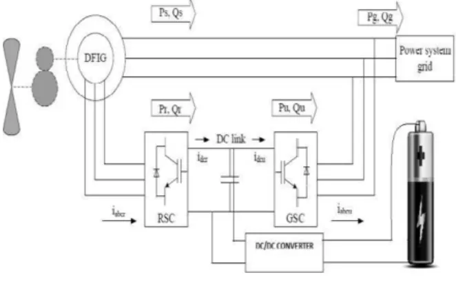
Fig. 2. DFIG connected to grid with battery via dc-dc converter.
Fig. 3. DFIG connected to grid with super-capacitor via dc-dc converter.
II. PROPOSED CONFIGURATION
Fig. 1 shows the configuration of a DFIG wind turbine connected to the grid without any Energy Storage (ES). Fig. 2 shows the configuration of a DFIG wind turbine equipped with a battery-based ES. Fig. 3 shows the configuration of a DFIG wind turbine equipped with a supercapacitor-based ES. The low speed wind turbine drives a high-speed DFIG through a gearbox. The DFIG is a wound-rotor induction machine. It is connected to the power grid at both stator and rotor terminals [9]. The stator is directly connected to the grid while the rotor is fed through a variable-frequency dc-link-voltage converter, which consists of a Rotor-Side Converter (RSC) and a Grid-Side Converter (GSC) and usually has a rating of a fraction (25%– 30%) of the DFIG nominal power. Its active and reactive powers can be controlled independently. In this paper, in first case an ES consisting of a battery bank and a two-quadrant dc/dc converter is connected to the dc link of the DFIG converters. The ES serves as either a source or a sink of active power, and therefore, contributes to control the generated active power of the wind turbine generator [6].
The DC-DC converter with the battery is used to maintain the voltage of the DC link relatively constant as the battery discharges and charges. The bidirectional DC-DC converter charges the battery in buck mode by reducing the voltage of the DC link. In the other direction, it acts in boost mode, discharging the battery to increase the voltage of the DC link [12]. The power conditioner injects or absorbs active power from the line through the filter to smooth the variable wind turbine output power. The relationship between the grid power, wind power and the power from battery is given by,
Where is the active power of the wind turbine, is the active power supplied by the battery/supercapacitor, and is the active power atthe grid interconnection point. In figure 3, a supercapacitor in place of battery is employed in the dc link via dc-dc converter. Then the results are observed for both cases and compared [10][18].
III. CONTROL OF DFIG WIND TURBINE AND DC-DC CONVERTER FOR ENERGY STORAGE There are mainly three control schemes which are implemented for Rotor Side Converter (RSC), Grid Side Converter (GSC), and DC-DC converter for energy storage.
A. Control for Rotor Side Converter
The main task of the Rotor Side Converter (RSC) is to track the maximum power point and operate the stator at unity power factor. The objective of the control of the rotor-side converter is to obtain a decoupled control between the stator active and reactive power. This can be achieved by choosing a synchronously rotating dq frame with the d-axis oriented along the stator flux vector position. Once the orientation is correctly done, an independent control of torque and flux is achieved i.e. the torque is controlled by torque producing current Irq. The stator flux is determined by stator voltage as the stator windings are directly connected to the main grid. The stator flux angle θs can be calculated by measuring stator current and voltage. The implemented control scheme for rotor side converter is shown in Fig. 4 [1] [14].
B. Control for Grid Side Converter
The vector control scheme for the GSC, in which the control of the dc-link voltage Vdc and the reactive power Qg
exchanged between the GSC and the grid is achieved by means of current regulation in a synchronously rotating reference frame. The overall GSC control scheme consists of two cascaded control loops. The outer control loop regulates the dc-link voltage Vdc and the reactive power Qg,
respectively, which generates the reference signals. The outputs of the two current controllers are compensated, respectively, to form the total voltage control signals, Vdg
and Vqg. They are then used by the PWM module to
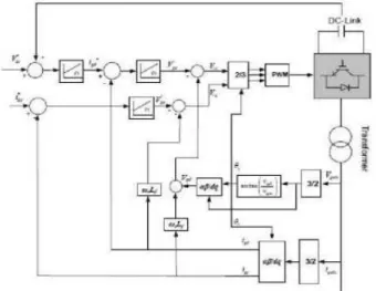
generate the gate control signals for the Grid Side Controller (GSC). The implemented control scheme for grid side converter is shown in Fig. 5 [1] [4].
Fig. 5. Grid Side Converter (GSC) control. C. Control for DC-DC Converter for Energy Storage In the charging mode, the terminal voltage of the battery/ supercapacitor increases, whereas in the discharging mode the terminal voltage of the battery/ supercapacitor is decreased.
Bidirectional DC- DC Converter:
The topology of the bi-directional DC-DC converter is shown in the Fig. 6. The bidirectional DC-DC converter acts as a buck converter in one direction and as a boost converter in the other direction [15]. Power IGBT/DIODES are used as the switching devices in the circuit. The operation of the converter is controlled by the DC link voltage and the voltage of the battery/ supercapacitor. The main purpose of the bidirectional DC-DC converter is to maintain the voltage of the DC link relatively constant at a reference value and fed a constant power to the grid. The DC-DC converter operating modes can be divided into four modes [18]. Mode 1: The DC-DC converter acts in buck mode, when the power generated by DFIG wind turbine is above the reference value power which is demanded by the grid. In this mode, the DC-DC converter allows the power flow to charge the battery/ supercapacitor.
Mode 2: The DC-DC converter acts in boost mode, when the power generated by DFIG wind turbine is below the reference value power which is demanded by the grid. In this mode, the battery/ supercapacitor energy is discharged to increase the power supplied to grid.
Mode 3: When the battery/ supercapacitor is fully charged, the DC-DC converter shuts down to avoid the damaging of the battery and the equipment.
Mode 4: When the battery/ supercapacitoris fullydischarged, the conditioner shuts down until charging of the battery/ supercapacitor may resume. The DC link capacitor is used as an intermediate element between the DC-DC converter and the converters [16]. The switching scheme for DC-DC converter is shown in Fig. 7
Fig. 6. DC-DC converter with Super-capacitor as Energy Storage (ES).
Fig. 7. Control scheme for Battery / Supercapacitor charging and discharging.
IV. SIMULATION AND RESULTS
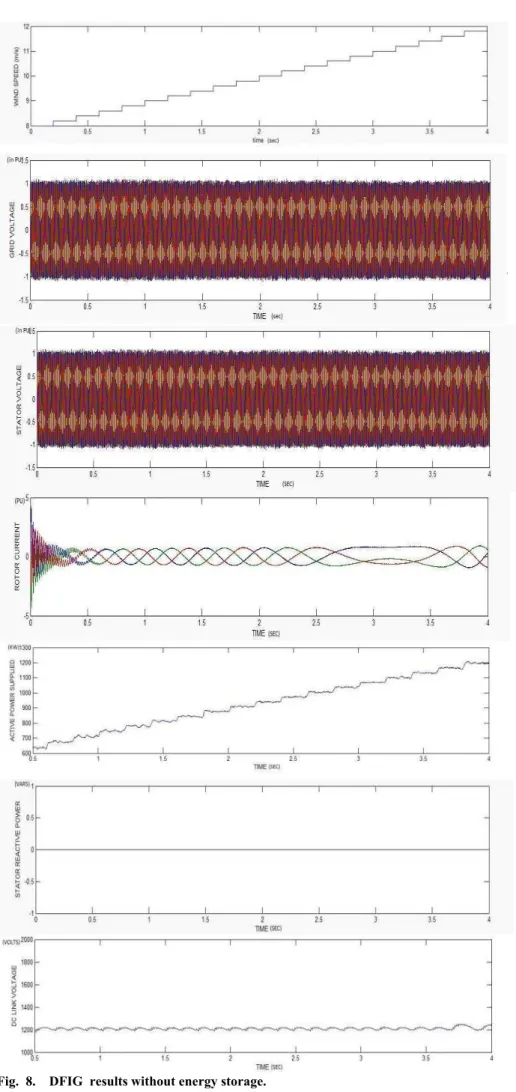
The model of the proposed system and its control has been developed using the SIMULINK software in MATLAB. Simulations are performed to investigate the performance of the battery and super-capacitor performances as energy storage. The variable output power of the wind turbine model developed in SIMULINK without energy storage is plotted.
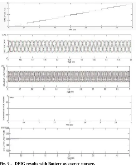
is implemented in dc link. The complete Simulink model of DFIG with battery as energy storage is shown in Fig. 9. The performance of the WECS with battery as energy storage at a wind speed varies from 8 to 12 m/s is shown in the Fig. 9. The active power supplied to the grid approximately varies from 600 kW to 1200 kW. The average power which can be fed to the grid constantly is 800 KW. This average power is decided by the wind profile data for 24 hours. To remove these power fluctuations a battery is implemented in dc link.
Initially the battery bank is taken as 80% charged. The reactive power drawn from the stator side (Qs) is zero i.e.stator is operating at unity power factor. Vdc is voltage of dc link or the battery bank which remains almost constant. The active power fed to the grid is maintained constant. Whenever the power generation exceed from the power to be injected in to the grid the battery charges and dc-dc converter operates in buck mode. But whenever the power generation is less from the power to be injected in to the grid the battery discharges and dc-dc converter operates in boost mode.
DFIG with super-capacitor as energy storage and the results for this model are shown in Fig. 10. The conventional DFIG is connected to the grid with super-capacitor as energy storage and its effects are observed. The wind speed is varied from 8m/s to 12m/s. Due to change in wind speed or increase in wind speed active power supplied to the grid is keep on increasing. This power fluctuation is removed with the help of super-capacitor energy storage and constant active power is supplied to the grid for short duration.
V. CONCLUSIONS
The conventional DFIG is connected to the grid and without any energy storage and normal operation is observed. The various quantities plots are observed with respect to time. The wind speed is varied from 8m/s to 12m/s. This paper describes the disadvantages of conventional DFIG scheme and suggests a new scheme with integrated energy storage (ES). The simulation results show the successful working of the modified new scheme with integrated storage system. The difference between battery and super-capacitor is that the battery can provide extra power for minutes to hours depending on the selected capacity, while the super-capacitor can provide extra energy for few seconds to minutes, only. It shows that super-capacitor is more suitable for voltage sag and swell, transient, fault ride through application or where the extra power demand is very low. But battery can be used for the support of large amount of power for a large time period.
REFERENCES
[1] LiyanQu, Wei Qiao "Constant Power Control of DFIG Wind Turbines with supercapacitor Energy Storage ," IEEE Transactions on Industry Applications, January 2011.
[2] Devon Manz, Richard Pikwo, NicholusMiller , "The Role Of Energy Storage In The Grid," IEEE Power And Energy Magazine, 18 June 2012.
[3] Armand Boyette and ShahrokhSaadate, "Direct and indirect control of a Doubly Fed Induction Generator wind turbine including a storage unit," IEEE, September 2006.
[4] Peiwen Li, "Energy Storage is The Core Of Renewable Energy Technologies," IEEE Nanotechnology Magazine December 2008. [5] M. Stanley Whittingham, "History, Evolution, And Future Status Of
Energy Storage," IEEE , Vol. 100, May 13th, 2012.
[6] Devon Manz, Richard Pikwo, NicholusMiller , "The Role Of Energy Storage In The Grid," IEEE Power And Energy Magazine, 18 June 2012.
[7] Domenico Casa, Gabriele Grandi ,Claudio Rossi, "A Super Capacitor Based Power Conditioning System Power Quality Improvement And Ups," IEEE 2002.
[8] S.M. Muyeen, Rion Takahashi, Toshiaki Murata " Integration of an energy capacitor system with a variable speed wind generator IEEE Transactions On Energy conversion, Vol. 24, No. 3, September 2009. [9] Energy Storage–A Key Enabler Of The Smart Grid Developed for the
U.S. Department of Energy September 2009.
[10] Vijay Chand Ganti, Bhim Singh, Fellow, IEEE, Shiv Kumar Aggarwal, and Tara Chandra Kandpa " DFIG-Based Wind Power Conversion With Grid Power Leveling for Reduced Gusts ," IEEE Transactions On Sustainable Energy, Vol. 3, No. 1, January 2012. [11] Sergio Vazquez, Srdjan M. Lukic, Eduardo Galvan, Leopoldo G.
Franquelo ,Juan M. Carrasco, " Energy Storage Systems for Transport and Grid Applications", IEEE Transactions On Industrial Electronics, Vol. 57, No. 12, December 2010.
[12] MuraliBottu, Mariesa L. Crow, " Design of a Coonditioner for Smoothing wind turbine output power ," IEEE, 2009.
[13] Murat Yilmaz Review of Battery Charger Topologies, Charging Power Levels and Infrastructure for Plug-in Electric and Hybrid Vehicles IEEE 2011.
[14] T. Coombs, A. M. Campbell, R. Storey, R Weller "Superconducting Magnetic Bearings for Energy Storage Flywheels." IEEE Transactions On Applied Superconductivity, Vol. 9, No. 2, June 1999. [15] Daniel H. Doughty, Paul C. Butler, Abbas A. Akhil, Nancy H. Clark,
and John D. Boyes , "Batteries for Large-Scale Stationary
[16] Electrical Energy Storage," The Electrochemical Society Interface • Fall 2010.
[17] M. Georgescu, L. Barote, C. Marinescu, L. Clotea, Members, " Smart Electrical Energy Storage System for Small Power Wind Turbines," 12th International Conference on Optimization of Electrical and Electronic Equipment, OPTIM 2010
[18] M. Al-Ramadhan and M. A. Abido "Design and Simulation of Supercapacitor Energy Storage System,"
[19] International Conference on Renewable Energies and Power Quality (ICREPQ’12) Spain, 28th to 30th March, 2012.
Fig. 9 . DFIG results with Battery as energy storage.