Lightweight Alkali-Activated Material from Mining and
1
Glass Waste by Chemical and Physical Foaming
2
Gediminas Kastiukas1, Ph.D., Xiangming Zhou2*, Ph.D., Kai Tai Wan3, Ph.D. and 3
João Castro Gomes4, Ph.D. 4
1Research Fellow, Department of Civil and Environmental Engineering, Brunel 5
University London, Uxbridge, Middlesex UB8 3PH, United Kingdom 6
2Professor, Department of Civil and Environmental Engineering, Brunel University 7
London, Uxbridge, Middlesex UB8 3PH, United Kingdom (http://orcid.org/0000-8
0001-7977-0718) 9
3Lecturer, Department of Civil and Environmental Engineering, Brunel University 10
London, Uxbridge, Middlesex UB8 3PH, United Kingdom 11
4Professor, Centre of Materials and Building Technologies, University of Beira 12
Interior, 6200 Covilhã, Portugal (http://orcid.org/0000-0002-2694-5462) 13
(*Corresponding author) e-mail: [email protected] 14
ABSTRACT 15
A foamed alkali-activated material (FAAM), based on tungsten mining waste (TMW) 16
and municipal waste glass (WG) was fabricated by using aluminium powder and 17
organic surfactant foaming agents. The compressive strength and density of the FAAM 18
were investigated in terms of different parameters of production and formulation 19
including curing temperature as well as the dosage of Na2O, foaming agent, foam 20
catalyzing agent and stabilizing agent. FAAM made with aluminium powder consisted 21
of smaller open macropores and exhibited higher compressive strength in comparison 22
with those of larger closed macropores obtained by the organic surfactant 23
counterparts. The final aluminium powder based FAAM reached a 7-day compressive 24
strength in excess of 3 MPa and a density below 0.7 g/cm3. The implementation of an 25
appropriate amount of foam stabilizer led to a further 15% increase in compressive 26
strength, 6% reduction in density and a thermal conductivity below 0.1 W/mK. The 27
FAAM explored in this study represents an ideal material for building envelop 28
insulation. 29
Keywords: Alkali-activation; aluminium powder; compressive strength; foamed 30
cementitious materials; geopolymer; waste glass; waste materials 31
1. Introduction 33
The development and application of lightweight cementitious materials have in the 34
past decades grown very rapidly and such materials are among the leading technology 35
in the “special purpose” concrete category [1]. Autoclaved aerated concrete (AAC) is 36
primarily used for making lightweight blocks to build partition walls. The lightweight 37
nature of the blocks means that they impose a minimum loading on the building and 38
provide good thermal and sound insulation [2]. Pre-fabricated panels can also be 39
made from lightweight cementitious materials with the latest innovation being hollow-40
core, interlocking panels [3]. Another useful application of lightweight cementitious 41
materials is void filling for structural stabilisation of disused structures [4]. 42
Approximately 70% of heat energy is lost through the building envelope from typical 43
residential housing without proper thermal insulation [5], making building insulation 44
one of the fastest growing applications of lightweight cementitious materials [4]. 45
The industry has been working hard to develop eco-friendly and energy efficient 46
construction materials due to the increase in market demand. With the exception of 47
organic insulation materials, which are based on a renewable and recyclable material, 48
polymer-based insulation materials are associated with a host of environmental 49
hazards in terms of toxicity. Polymer foam materials such as polystyrene and 50
polyethylene remain very popular materials for insulation and make up almost half of 51
the market [6]. Polystyrene is classified as a possible human carcinogen [7], and the 52
production of Expanded Polystyrene Foam (EPS) has a global warming potential 53
(GWP) 7 times greater than carbon dioxide [8]. Hence, the use of lightweight 54
cementitious materials can constitute an effective way of energy-conservation and 55
environmental-protection, particularly for the thermal-insulation engineering of 56
buildings. 57
Currently, technologies for insulating performance are being explored, like aerogels 58
[9] and Vacuum Insulating Panels (VIPs) [10]. However, these cannot be produced in 59
a cost-effective manner and are too fragile to meet the durability needs that are critical 60
for mainstream building products (e.g. VIPs cannot be nailed, and lose thermal 61
resistance rapidly if perforated), making them impractical solutions for today's building 62
environment. 63
There were several recent studies about lightweight foamed alkali-activated materials 64
(AAM), which are referred to as geopolymers in some literature as well, based on fly 65
ash [11] and bottom ash [12]. AAMs have been demonstrated to possess many of the 66
necessary qualities a lightweight cementitious material should display, namely high 67
temperature resistance [13], low shrinkage [14], low coefficient of permeability [15], 68
low thermal conductivity [16] and good nailability [17]. Also, the appeal of being able 69
to use high volumes of industrial waste materials for the production of AAMs and thus 70
contest the environmental pollution of Portland cement is an added benefit. 71
So far, in building applications, the research into foamed alkali-activated materials 72
(FAAMs) is limited to structural grade concrete with mid-range densities of 1300-1700 73
kg/m3 and compressive strengths of 13-15 MPa [13], [18]–[20]. Out of the few studies 74
conducted to produce high-performance FAAMs, the resulting materials possessed 75
either high insulating properties coupled with very low compressive strength [21] or 76
high compressive strength coupled with poor thermal insulating properties [16]. 77
However, to the author’s best knowledge, the use of FAAMs as a high-performance 78
insulation material with high mechanical resistance and low thermal conductivity has 79
not been proven. 80
In this study, the potential of producing a high-performance FAAM made entirely from 81
tungsten mining waste and municipal waste glass which could satisfy not only thermal 82
performance but also mechanical strength requirements of similar grade products was 83
investigated. The compatibility of a natural foam catalyser and foam stabilising agent 84
were investigated in order to improve both the thermal insulation and compressive 85
strength performance. In addition, the preparation of a FAAM using mechanically pre-86
formed foam composed of an anionic surfactant and the alkali-activator, never 87
reported in previous works, was studied. 88
2. Materials and Methods 89
2.1 Materials and chemicals 90
The precursor materials used to produce the FAAM in this investigation consisted of 91
tungsten mining waste (TMW) and municipal waste glass (WG). The TMW was 92
derived in powder form from the Panasqueira mine in Castelo Branco, Portugal, while 93
the WG was received from the local municipality of Covilhã, Portugal. The micro-94
morphology of the TMW and WG can be seen in our previous study [22]. The chemical 95
composition of TWM and WG from a sequential benchtop wavelength dispersive X-96
ray fluorescence (WD-XRF) spectrometer (Supermini200, Rigaku, Japan mounted 97
with LiF(200) and PET crystals), is shown in Table 1. The raw materials used for the 98
alkali activator were 98% pure sodium hydroxide (NaOH) (SH) (Fisher Scientific, 99
Germany), and sodium silicate (Na2SiO3) (SS) (Solvay SA, Portugal). 100
Table 1. Chemical composition (wt %) of TMW and WG determined by WD-XRF 102 Component TMW WG Na2O 0.51 12.44 MgO 2.16 1.76 Al2O3 14.89 2.12 SiO2 49.17 68.71 SO3 8.98 0.33 K2O 2.92 0.77 Fe2O3 13.69 1.48 CaO 0.58 10.04 P2O5 0.32 0.00 TiO2 0.5 0.00 ZnO 1.25 0.00 CuO 0.32 0.00 As2O3 4.26 0.00
Foaming was achieved by either a chemical foaming technique or physical foaming 103
technique. Aluminium powder (purity of 99 %, average particle size of 75 microns and 104
molar mass of 26.98 g/mol, Sigma Aldrich, UK) was used as the foaming agent of the 105
chemical foaming technique. Sodium dodecyl benzenesulfonate (SDBS, Sigma 106
Aldrich, UK, molecular weight of 348.48 g/mol), was used for the physical foaming 107
technique due to its ionic nature and thus enhanced foam stability compared to non-108
ionic surfactants [23]. 109
Manganese dioxide (MnO2, particle size of less than 10 microns and a molecular 110
weight of 86.94 g/mol, Sigma Aldrich, UK) was used to catalyse the reaction of the 111
chemical foaming process. Also, starch (Sigma-Aldrich, UK) which is a natural, high-112
polymeric carbohydrate was used to stabilise the chemical foaming process. 113
2.2 Methods 114
Firstly, essential parameters associated with the production of a FAAM were 115
investigated, namely the curing temperature and dosage of Na2O (mass ratio of total 116
Na2O in the activating solution to precursor). The optimum curing temperature and 117
dosage of Na2O in terms of density were used as benchmarks and carried forward to 118
produce the reference sample for evaluating the effects of manganese dioxide and 119
starch. 120
The mix parameters analysed through a laboratory experiment of 18 TMW-WG-FAAM 121
samples were curing temperature (40˚C, 60˚C, 80˚C and 100˚C), dosage of Na2O 122
(3.1%, 3.3% and 3.5%), wt.% of aluminium powder (3, 6 and 9), wt.% surfactant (2, 4 123
and 6), wt.% MnO2 (0.2, 0.4 and 0.6) and wt.% starch (2, 4 and 6). 124
All sample preparation was carried out in a laboratory maintained at 20°C. For the 125
preparation of the non-foamed base TMW-WG-AAM, the synthesis conditions for 126
achieving the highest strength and satisfactory workability were adopted based on 127
previously published results [24]. The precursor consisted of TMW and WG with a 128
mass ratio of 3:2. The alkali activating solution consisted of 10M sodium hydroxide 129
solution (plus the sodium silicate concentration) and 8 wt.% of water. The mass ratio 130
of the alkali activating solution and precursor was fixed at 0.22. 131
To determine the relationship between the various parameters and indicators, the 132
horizontal x-axis presented the parameters, i.e. curing temperature, dosage of Na2O 133
(in %), foaming agent, manganese dioxide and starch contents, while the vertical y-134
axis’ presented the average of the assessment indicators, i.e. compressive strength 135
and density. 136
2.2.1 Chemical Foaming Method 138
The principle of chemical foaming with aluminium powder is based on the reaction 139
between aluminium and SH to produce H2 gas, which initiates the expansion of the 140
system according to the following chemical reaction formula [25]: 141
2Al + 2NaOH + 6H2O = 2NaAl(OH)4 + 3H2 (Eq. 1) 142
The TMW and WG were dry-blended in a commercial mixer at 300 rpm for five 143
minutes, forming the precursor materials. The alkali activating solution was slowly 144
added to the precursor materials and then stirred for 2.5 minutes at 200 rpm, followed 145
by 2.5 minutes at 500 rpm to form the AAM paste. The aluminium powder was 146
subsequently added to the AAM by weight of sodium hydroxide and stirred for a further 147
1 minute at 350 rpm. Plastic 4 x 4 x 16 cm3 molds were filled with the paste in two 148
stages. The TMW-WG-FAAM was then left to rest until the foaming process was 149
complete. The rest period depended on the quantity of aluminium powder and the 150
dosage of Na2O since different combinations produced different rates of expansion. 151
2.2.2 Mechanically Pre-Formed Foaming Method 152
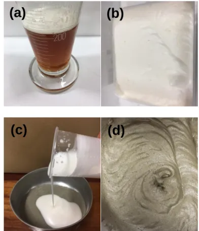
The anionic surfactant and the alkali activating solution were combined together (Fig. 153
1a) and then mixed at 1200 rpm for 5 minutes to form the foamed alkali activating 154
solution (Fig. 1b). TMW and WG were dry-blended in a commercial mixer at 300 rpm 155
for 5 minutes, forming the precursor materials and the foamed alkali activating solution 156
was mixed into the precursor at 300 rpm for 5 minutes (Fig 1c). Finally, Fig. 1d exhibits 157
the fresh surfactant TMW-WG-FAAM immediately after mixing. A beater attachment 158
was used for the mixing to allow more air to be entrapped into the TMW-WG-FAAM. 159
161
162
Fig. 1. Preparation of surfactant TMW-WG-FAAM showing (a) the alkali activator/surfactant mixture (b)
163
prepared foam (c) combination of the precursors and foam (d) surfactant TMW-WG FAAM
164 165
2.2.3 FAAM Heat Curing Method 166
The specimens were placed in a temperature and humidity controlled environmental 167
chamber at 95 %RH. The curing temperature was initially evaluated between 40°C 168
and 100°C, with the most appropriate temperature in terms of compressive strength 169
carried forward for the production of subsequent FAAM samples. After 24 hours of 170
curing, the prismatic FAAM samples were demoulded and each of them was then cut 171
into three 40 x 40 x 40 mm3 cubes. 172
2.2.4 Thermal Conductivity 173
The thermal conductivity was measured with a thermal conductivity meter (Fox 200, 174
TA Instruments, USA). The steady state heat flux through the 150 x 150 x 25 mm3 175
rectangular block samples were measured for a temperature gradient of 10°C between 176
the upper and the lower face of the sample. Three identical samples for each TMW-177
(c)
(d)
WG-FAAM were measured for evaluation of the thermal conductivity. Before 178
measurement, the samples were left for 12 h at 80°C and placed in a dry chamber for 179
cooling for 30 minutes without moisture absorption. 180
2.2.5 Compressive Strength 181
The compressive strength of the TMW-WG-FAAM cubes was tested after 7 days in 182
accordance with EN 196-1 using a 50kN universal testing machine (Instron 5960, UK) 183
at a constant loading rate of 3 kN/min. The compressive strength value was the 184
average of values obtained from three specimens. 185
2.2.6 Imaging 186
TMW-WG-FAAM samples were vacuum impregnated with epoxy resin doped with a 187
fluorescent dye (EpoDye, Solvent Yellow 43, Denmark) to highlight the pores. The 188
samples were polished using a bench-top planar grinding machine (PlanarMet 300, 189
Buehler USA) and imaged using a fluorescence microscope (Leica M205 FCA, UK). 190
Images were analysed using open source software (ImageJ) using a sample surface 191
area of 22 x 22 mm. 192
3. Results and Discussion 193
3.1 TMW-WG FAAM by chemical foaming technique 194
3.1.1 Effect of heat curing 195
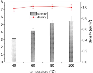
Fig. 2 shows the effect of curing temperature on the 7-day compressive strength and 196
density of the TMW-WG-FAAM samples using 6% wt. of aluminium powder, a Na2O 197
of 3.1% and additional 8% wt. of mixing water. It is evident the compressive strength 198
of the sample increased with curing temperature, while the density remained in 199
practical terms unchanged within the range of 0.97 and 1.01 g/cm3. As expected, the 200
lowest compressive strength was attained by the sample cured at the lowest 201
temperature (i.e. 40°C), reaching 3.15 MPa. Likewise, the compressive strength 202
increased with increase in curing temperature due to the accelerated ion diffusion rate 203
between the liquid and solid material thus producing a denser colloidal structure [26]. 204
TMW-WG-FAAM samples cured at the highest temperature, i.e. 100°C obtained a 205
compressive strength of 5.45 MPa. The ultimate compressive strength and density of 206
the samples were not found to be interdependent, and thus the optimal curing 207
temperature of TMW-WG-FAAM may be based on a compromise of the compressive 208
strength. In this case, the 80°C cured sample attained only a 4.6% lower compressive 209
strength over the 100°C cured sample but consumed approximately 40 kWh less 210
energy during curing (based on the energy performance of a Weiss C340-40 model 211
environmental chamber operating for 24 hours). By considering the energy 212
consumption during manufacturing, mechanical performance and thermal resistance, 213
curing at 80°C was chosen to be the optimum curing temperature, in line with results 214
obtained by other studies [27] and thus used for the preparation of all subsequent 215
samples. 216
40 60 80 100 0 1 2 3 4 5 6 7 8 strength density temperature (C) co mpr es si ve s tre ng th (MPa) 0.0 0.2 0.4 0.6 0.8 1.0 de ns ity (g /c m 3 ) 218
Fig. 2. Effect of curing temperature on compressive strength and density of aluminium powder TMW
-219
WG FAAM
220
3.1.2 Effect of dosage of Na2O
221
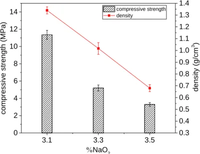
Fig. 3 demonstrates the effect of the 3.1%, 3.3% and 3.5% of Na2O on the 7-day 222
compressive strength and density of the TMW-WG-FAAM samples made using 6% 223
wt. of aluminium powder and 8% wt. of mixing water. It was clear that the density of 224
TMW-WG-FAAM reduced with increase of the %Na2O. The formation of H2 gas led to 225
a foaming effect which would be enhanced with the increase of SH. Increasing the 226
dosage of Na2O from 3.1% to 3.5% reduced the density by 49% from 1.34 g/cm3 to 227
0.67 g/cm3. The increased foaming increased the porosity and reduced the density, 228
but was naturally coupled by a reduction in the compressive strength of the TMW-WG-229
FAAM. In this case, the compressive strength reduced from 11.36 MPa to 3.3 MPa. 230
Under normal circumstances, aluminium does not react with water, as an impermeable 231
protective layer composed of aluminium hydroxide forms within seconds [25]. With the 232
addition of sodium hydroxide, the aluminium hydroxide goes into solution, and 233
the layer of aluminium oxide previously formed by passive corrosion is dissolved. For 234
this reason, the alkali activating solution with a low Na2O (less than 3.1%) involved a 235
very slow reaction due to insufficient SH, leading to reduced volumetric expansion of 236
the foam. 237
3.1 3.3 3.5 0 2 4 6 8 10 12
14 compressive strength density
NaO2 co mpr es si ve s tre ng th (MPa) 0.3 0.4 0.5 0.6 0.7 0.8 0.9 1.0 1.1 1.2 1.3 1.4 de ns ity (g /c m 3 ) 238
Fig. 3. Effect of %NaO2 on compressive strength and density of aluminium powder AAFM 239
3.1.3 Effect of aluminium powder content 240
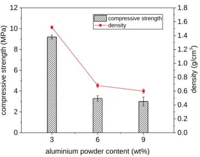
Fig. 4 shows the effect of 3% wt., 6% wt. and 9% wt. aluminium powder dosage on the 241
7-day compressive strength and density of the TMW-WG-FAAM sample made using 242
dosage of Na2O of 3.5% and 8% wt. mixing water. The sample density obtained with 243
3% wt. of aluminium powder was 1.52 g/cm3, which went on to decrease to 0.68 g/cm3 244
and 0.6 g/cm3 for 6% wt. and 9% wt. aluminium powder dosages, respectively. The 245
compressive strength also experienced a reduction by 67% from 9.2 MPa to 3 MPa, 246
respectively. The reduction in compressive strength with increase in aluminium 247
powder dosage was expected and due to the straightforward fact that more aluminium 248
powder was available to react with the SH, producing more H2 gas. Additionally, the 249
high reaction rate between the aluminium powder and SH would have also led to the 250
premature depletion of SH, reducing its availability for the required dissolution of 251
aluminosilicate precursors; a factor known to interrupt the attainment of mechanical 252
strength in AAMs [28]. It can also be deduced that the extent to which the foaming 253
action and thus reduction in density occurs is less dominant with the increase of 254
aluminium powder than with the increase of the alkali content i.e. %Na2O. The latter 255
would make the alkali content and thus the appropriate optimisation of the activating 256
solution the controlling factor in aluminium powder FAAMs. 257 3 6 9 0 2 4 6 8 10 12 compressive strength density
aluminium powder content (wt%)
co mpr es si ve s tre ng th (MPa) 0.0 0.2 0.4 0.6 0.8 1.0 1.2 1.4 1.6 1.8 de ns ity (g /c m 3 ) 258
Fig. 4. Effect of aluminium powder on compressive strength and density of aluminium powder FAAM
259
3.1.4 Effect of manganese dioxide content 260
Fig. 5 compares the effect of 0.2% wt., 0.4% wt. and 0.6% wt. manganese dioxide 261
catalysing agent dosage on the 7-day strength of TMW-WG-FAAM sample made 262
using 6% wt. aluminium powder, 3.5% dosage of Na2O and 8% wt. mixing water. With 263
the initial presence of 0.2% wt. manganese dioxide, it is observed that the compressive 264
strength of TMW-WG-FAAM significantly dropped by 61% from 3.3 MPa to 1.27 MPa. 265
From 0.2 to 0.4 wt% and finally to 0.6 wt%, there appeared to be much steadier 266
reduction in the density and compressive strength. The large initial drop and 267
subsequent gradual reduction in density and thus compressive strength was due to 268
the thermite reaction between the manganese dioxide and the aluminium powder 269
foam. With the presence of manganese dioxide the foaming action was observed to 270
be more unstable, resulting in excessive bubble size and their subsequent rupture. 271
Therefore, it could be concluded that the incorporation of manganese dioxide should 272
be avoided in aluminium powder FAAMs. 273
0 0.2 0.4 0.6 0.0 0.5 1.0 1.5 2.0 2.5 3.0 3.5 4.0 compressive strength density MnO2 content (wt%) co mpr es si ve s tre ng th (MPa) 0.30 0.35 0.40 0.45 0.50 0.55 0.60 0.65 0.70 0.75 de ns ity (g /c m 3 ) 274
Fig. 5. Effect of manganese dioxide on compressive strength and density of 6% wt. aluminium powder
275
TMW-WG FAAM
276
3.1.5 Effect of starch content 277
Fig. 6 shows the effect of 2% wt., 4% wt. and 6% wt. starch on the density and 278
compressive strength of TMW-WG-FAAM made with 6 wt% aluminium powder, 3.5% 279
Na2O and 8 wt% mixing water. With the addition of 2% wt. starch, the density only 280
marginally reduced from 0.68 g/cm3 to 0.64 g/cm3, while the compressive strength 281
showed more noteworthy increase from 3.3 MPa to 3.8 MPa. This indicated that starch 282
did not necessarily participate in the chemical foaming process but however improved 283
the compressive strength. Starch being a polysaccharide was likely able to achieve 284
this improvement in compressive strength due to its aggregating action in 285
aluminosilicate interparticle bonds [29]. Nonetheless, when the starch concentration 286
increased to 4% wt. and followed by 6% wt, the compressive strength significantly 287
decreased, coupled by the increase in the density. The addition of starch above 2% 288
wt. increased the relative concentration of particles in the system thus increasing the 289
reaction time and subsequent formation of reaction products. The loss of compressive 290
strength could be explained by the reduced liquid-solid ratio due to the low molecular 291
weight of starch, resulting in a prolonged coagulation time of the FAAM and reduced 292
paste fluidity. The reduced fluidity due to the increased starch content created an 293
open-textured material, and as revealed in Fig. 7, allowed the bubbles to coalesce 294
(circled in black), and the H2 gas generated during the aluminium powder and SH 295 reaction to escape. 296 0 2 4 6 0.0 0.5 1.0 1.5 2.0 2.5 3.0 3.5 4.0 4.5 5.0 compressive strength density starch content (wt%) co mpr es si ve s tre ng th (MPa) 0.0 0.1 0.2 0.3 0.4 0.5 0.6 0.7 0.8 de ns ity (g /c m 3 ) 297
Fig. 6. Effect of starch on compressive strength and density of aluminium powder TMW-WG FAAM
298
299
Fig. 7. TMW-WG FAAM made with 6% wt. starch
300
3.2 TMW-WG FAAM by physical foaming technique 301
2% wt., 4% wt and 6% wt. anionic surfactant were investigated in the preparation of 302
the surfactant TMW-WG-FAAM. In all cases, the precursor-to-foam ratio was 303
maintained at a constant ratio of 0.6. 304
3.2.1 Effect of surfactant content 305
Fig. 8 compares the effect of 2% wt., 4% wt and 6% wt. anionic surfactant on the 306
compressive strength and density of the TMW-WG-FAAM samples made with 3.5% 307
of Na2O and 8 wt% mixing water. The compressive strength of the samples was 308
observed to increase with an increase in the dosage of surfactant from 2% wt. to 4% 309
wt. by 40% from 1.59 MPa to 2.68 MPa, respectively. However, the density remained 310
steady between 0.71 and 0.75 g/cm3. The increase in surfactant from 2% wt. to 4% 311
wt. did not lead to an entrainment of more air in the sample thus explaining the 312
approximately constant density. Upon the addition of 6% wt. surfactant, the density of 313
the sample increased coupled by a reduction in the compressive strength. A likely 314
explanation of the foaming inhibition with increased amounts of surfactant may be due 315
to the presence of Ca+ and Mg+ ions from the precursor materials i.e. the TMW and 316
WG which would have a strong affinity to the negatively charged carboxylate end of 317
the surfactant molecule. This would essentially deactivate the surfactant and thus 318
interrupt the foaming. Furthermore, increased surfactant content may have also led to 319
an unnecessary high foam content, increasing the drainage of water around the foam 320
thus increasing the likelihood of bubble collapse. However, further tests of increased 321
surfactant content will have to be performed to confirm its impact on the compressive 322
strength of TMW-WG-FAAM. 323
2 4 6 0.0 0.5 1.0 1.5 2.0 2.5 3.0 3.5 4.0 compressive strength density surfactant content (wt.%) co mpr es si ve s tre ng th (MPa) 0.0 0.1 0.2 0.3 0.4 0.5 0.6 0.7 0.8 0.9 1.0 1.1 1.2 de ns ity (g /c m 3 ) 325
Fig. 8. Effect of surfactant on compressive strength and density of surfactant TMW-WG-FAAM
326
3.3 FAAM Pore Imaging and Thermal Conductivity 327
Grey level histogram analysis followed by a noise cleaning process were performed 328
on medium magnification grey-scale surface images of TMW-WG-FAAM made with 329
aluminium powder and surfactant. This procedure revealed clear outlines of all the 330
pores and allowed for the calculation of their size by dividing the sum of their pixels by 331
the total pixels in the image. Images of the deconvoluted TMW-WG-FAAM pore 332
structures are presented in Fig. 9. TMW-WG-FAAM made by chemical foaming 333
technique in Fig. 9a shows that most of the pore walls, or surfaces of the pores, are 334
broken and interconnected, indicating that an open pore structure formed during 335
foaming between the aluminium powder and SH. In comparison, most of the pores in 336
TMW-WG-FAAM by physical foaming technique shown in Fig. 9b are spheroidal but 337
possess little connectivity, indicating that the use of a surfactant as a foaming agent 338
leads to a closed foam structure. Also, the average area of the pores TMW-WG-FAAM 339
by physical foaming technique, calculated at 0.127 mm2 (excluding the three large 340
pores at the bottom right which are assumed to have formed during compaction) was 341
10% lower than the average pore size of the TMW-WG-FAAM by chemical foaming 342
technique, calculated at 0.141 mm2. It is the former open cell structure and larger 343
average pore size of the by chemical foaming technique which would allow for more 344
air to be trapped within the material, thus leading to a lower density and thus thermal 345
conductivity. 346
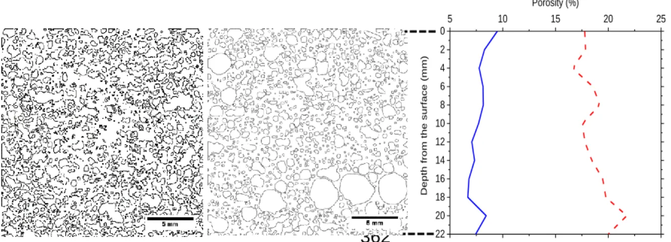
Using the images in Fig. 9a and 9b, a quantification of pore area distribution using the 347
variation of the pore area fraction along the depth of the specimens were also 348
performed. The images were divided into 2 mm deep x 22 mm wide strips, and the 349
pore area fractions in each of the strips were determined. The variation of pore area 350
shown in Fig. 9c corresponds to the average of pore area fraction measurements on 351
eleven different horizontal sections for TMW-WG FAAM foamed with aluminium 352
powder and surfactant. It can be noticed that there is a lower variation with depth in 353
the pore area fraction for the TMW-WG FAAM made with surfactant. The latter 354
indicates a more uniform distribution of pores across the TMW-WG FAAM made with 355
surfactant and corroborated with observations from Fig. 9b which show it to possess 356
more spherical and uniformly distributed pores. For the TMW-WG FAAM made with 357
aluminium powder, a higher degree of variation is observed through the image 358
analysis, implying a less stable foam structure and the possibility of foam clogging, 359
particularly at the top of the sample where the porosity was determined to be 360
approximately 18% less than at the bottom of the sample. 361 5 10 15 20 25 22 20 18 16 14 12 10 8 6 4 2 0 Porosity (%) Depth fro m th e su rfa ce ( mm) 362
Fig. 9. (a) Pore distribution of TMW-WG FAAM foamed with (a) aluminium powder and (b) surfactant.
363
(c) Variation of pore area fraction in TMW-WG FAAM made with aluminium powder and surfactant.
365
Table 2 summarises the primary TMW-WG-FAAM properties, i.e. density, 7-day 366
compressive strength and thermal conductivity for samples produced with the 367
aluminium powder and surfactant foaming agents. Due to the open pore structure of 368
TMW-WG-FAAM by chemical foaming technique, it is clear to understand why it 369
achieved a lower density of 0.64 g/cm3 and a thermal conductivity of 0.09 W/mK. The 370
TMW-WG-FAAM by physical foaming technique achieved both a higher density and 371
higher thermal conductivity of 0.77 g/cm3 and 0.16 W/mK, respectively due to the 372
closed pore structure and smaller average pore area. In practice, closed cell structures 373
usually possess higher compressive strengths due to the higher core density but in 374
the case of the open cell TMW-WG-FAAM by chemical foaming technique, it achieved 375
a compressive strength of 3.8 MPa compared to the closed foam structure of the TMW-376
WG-FAAM by physical foaming technique of 2.68 MPa. This is an interesting 377
observation and leads to the postulation that the chemical foaming technique is not 378
only linked to pore characteristics such as shape and connectivity as previously 379
mentioned, but also to its strength. In this case, the TMW-WG-FAAM by chemical 380
foaming technique can be thought to have contributed to reinforcing the pore wall 381
structure; however, this would require further investigation. 382
Table 2 also lists thermo-physical properties of traditional cement-based insulation 383
materials and recently published foamed alkali-activated materials. By comparing 384
between the best performing TMW-WG-FAAM reported in this study (prepared with 6 385
wt.% aluminium powder and 2% wt. starch) and other materials, the TMW-WG-FAAM 386
significantly outperforms the traditional cement-based insulation materials such as 387
AAC, foamed concrete and cement expanded vermiculite in terms of thermal 388
conductivity while the combination of density and compressive strength is also 389
unmatched. 390
Table 2.Thermo-physical properties of TMW-WG-FAAM, traditional cement-based insulation materials
391
and alkali activated foam materials
392 Sample Density (g/cm3) Compressive strength (MPa) Thermal conductivity (W/mK) Unfoamed TMW-WG-AAM 2.10 61.0 0.280 6% wt. aluminium powder
TMW-WG-FAAM with 2% wt. starch 0.64 3.8 0.090
4% wt. surfactant TMW-WG-FAAM 0.77 2.68 0.150
Aerated concrete (AAC) [30] 0.60 4.5 0.160
Foamed concrete [31] 0.60 5.2 0.165
‘Inorganic foams’ [30] 0.67 6.0 0.145
‘Geopolymer foam concrete’ [32] 0.60 1.3 0.470
‘Geopolymer foam’ [33] 0.58 4.4 0.158
‘Porous fly ash-GP’ [29] 0.56 1.23 0.107
393
4 Conclusions 394
This study revealed that alkali-activated foamed materials (FAAMs) based on tungsten 395
mining waste and waste glass could be successfully prepared by a chemical foaming 396
method using aluminium powder and a physical foaming method by using pre-formed 397
foam with an anionic surfactant. The following conclusions can be drawn from the 398
results of this work: 399
The curing temperature of TMW-WG-FAAM influenced the mechanical strength 400
but did not affect the density. The final pore structure is formed during the initial 401
foaming process and thus curing temperature was chosen based on adequate 402
compressive strength development, which in this case was 80°C. 403
The alkali content is strongly related to both the density and compressive 404
strength of TMW-WG-FAAM making it more of a dominant control factor 405
compared to the content of aluminium powder. A NaO2 dosage lower than 3.1% 406
involves a very slow reaction due to insufficient NaOH, leading to a reduced 407
volume of foaming. 408
The chemical foaming method with aluminium powder resulted in the creation 409
of an open cell pore structure leading to a significantly lower thermal 410
conductivity and density, coupled with enhanced compressive strength. 411
Use of manganese dioxide foam catalyst agent, even at relatively low levels 412
(0.2% wt.), resulted in unstable chemical foaming with aluminium powder and 413
compromised compressive strength. On the other hand, the use of starch as a 414
foam stabilising agent led to improved compressive strengths without affecting 415
the density. 416
The combined technical and sustainable advantages of TMW-WG-FAAM make 417
it a viable route to yield insulating materials comparable to both traditional 418
cement-based insulation materials and other recently reported foamed alkali-419
activated materials. 420
Acknowledgement 422
Partial finance support from the European Commission Horizon 2020 MARIE 423
Skłodowska- CURIE Research and Innovation Staff Exchange scheme through the 424
grant 645696 (i.e. the REMINE project) is greatly acknowledged. 425
References 426
[1] R. K. Dhir, M. D. Newlands, and A. McCarthy, Use of Foamed Concrete in Construction. Thomas Telford
427
Publishing, 2005.
428
[2] M. A. Mousa and N. Uddin, “Experimental and analytical study of carbon fiber-reinforced polymer ( FRP
429
)/ autoclaved aerated concrete ( AAC ) sandwich panels,” Eng. Struct., vol. 31, no. 10, pp. 2337–2344,
430
2009.
431
[3] W. A. Thanoon, M. S. Jaafar, M. R. A. Kadir, A. A. A. Ali, D. N. Trikha, and A. M. S. Najm, “Development of
432
an innovative interlocking load bearing hollow block system in Malaysia,” Constr. Build. Mater., vol. 18,
433
no. 6, pp. 445–454, 2004.
434
[4] Y. H. M. Amran, N. Farzadnia, and A. A. A. Ali, “Properties and applications of foamed concrete: a review,”
435
Constr. Build. Mater., vol. 101, no. Part 1, pp. 990–1005, 2015.
436
[5] M. O’Grady, A. A. Lechowska, and A. M. Harte, “Quantification of heat losses through building envelope
437
thermal bridges influenced by wind velocity using the outdoor infrared thermography technique,” Appl.
438
Energy, 2017.
439
[6] L. Shen, J. Haufe, and M. K. Patel, “Product overview and market projection of emerging bio-based
440
plastics,” 2009. [Online]. Available: https://goo.gl/5Qwvy3. [Accessed: 13-Nov-2017].
441
[7] J. Unwin, M. R. Coldwell, C. Keen, and J. J. McAlinden, “Airborne Emissions of Carcinogens and
442
Respiratory Sensitizers during Thermal Processing of Plastics,” Ann. Occup. Hyg., vol. 57, no. 3, pp. 399–
443
406, 2013.
444
[8] N. Pargana, M. D. Pinheiro, J. D. Silvestre, and J. de Brito, “Comparative environmental life cycle
445
assessment of thermal insulation materials of buildings,” Energy Build., vol. 82, no. Supplement C, pp.
446
466–481, 2014.
447
[9] R. Baetens, B. P. Jelle, and A. Gustavsen, “Aerogel insulation for building applications: A state-of-the-art
448
review,” Energy Build., vol. 43, no. 4, pp. 761–769, 2011.
449
[10] R. Baetens, B. P. Jelle, J. V. Thue, M. J. Tenpierik, S. Grynning, S. Uvsløkk, and A. Gustavsen, “Vacuum
450
insulation panels for building applications: A review and beyond,” Energy Build., vol. 42, no. 2, pp. 147–
451
172, 2010.
452
[11] N. Ismail, D. Ph, H. El-hassan, D. Ph, and M. Asce, “Development and Characterization of Fly Ash – Slag
453
Blended Geopolymer Mortar and Lightweight Concrete,” vol. 30, no. 4, pp. 1–14, 2018.
454
[12] G. Görhan and G. Kürklü, “The influence of the NaOH solution on the properties of the fly ash-based
455
geopolymer mortar cured at different temperatures,” Compos. Part B Eng., vol. 58, pp. 371–377, 2014.
456
[13] H. Cheng-yong, L. Yun-ming, M. Mustafa, and A. Bakri, “Thermal Resistance Variations of Fly Ash
457
Geopolymers : Foaming Responses,” Nat. Publ. Gr., no. February, pp. 1–11, 2017.
458
[14] P. Duxson, A. Fernández-Jiménez, J. L. Provis, G. C. Lukey, A. Palomo, and J. S. J. van Deventer,
459
“Geopolymer technology: the current state of the art,” J. Mater. Sci., vol. 42, no. 9, pp. 2917–2933, 2007.
460
[15] N. Tenn, F. Allou, C. Petit, J. Absi, and S. Rossignol, “Formulation of new materials based on geopolymer
461
binders and different road aggregates,” Ceram. Int., vol. 41, no. 4, pp. 5812–5820, May 2015.
462
[16] M. R. Wang, D. C. Jia, P. G. He, and Y. Zhou, “Influence of calcination temperature of kaolin on the
463
structure and properties of final geopolymer,” Mater. Lett., vol. 64, no. 22, pp. 2551–2554, 2010.
464
[17] P. Duan, C. Yan, W. Zhou, and W. Luo, “Fresh properties, mechanical strength and microstructure of fly
465
ash geopolymer paste reinforced with sawdust,” Constr. Build. Mater., vol. 111, no. Supplement C, pp.
466
600–610, 2016.
467
[18] M. Y. J. Liu, U. J. Alengaram, M. Z. Jumaat, and K. H. Mo, “Evaluation of thermal conductivity, mechanical
468
and transport properties of lightweight aggregate foamed geopolymer concrete,” Energy Build., vol. 72,
469
no. Supplement C, pp. 238–245, 2014.
470
[19] Z. Zhang, J. L. Provis, A. Reid, and H. Wang, “Mechanical, thermal insulation, thermal resistance and
471
acoustic absorption properties of geopolymer foam concrete,” Cem. Concr. Compos., vol. 62, pp. 97–
472
105, 2015.
[20] M. M. A. B. Abdullah, K. Hussin, M. Bnhussain, K. N. Ismail, Z. Yahya, and R. Abdul Razak, “Fly Ash-based
474
Geopolymer Lightweight Concrete Using Foaming Agent,” Int. J. Mol. Sci., vol. 13, no. 6, pp. 7186–7198,
475
2012.
476
[21] J. Feng, R. Zhang, L. Gong, Y. Li, W. Cao, and X. Cheng, “Development of porous fly ash-based geopolymer
477
with low thermal conductivity,” Mater. Des., vol. 65, pp. 529–533, 2015.
478
[22] G. Kastiukas, X. Zhou, and J. Castro-Gomes, “Development and optimisation of phase change
material-479
impregnated lightweight aggregates for geopolymer composites made from aluminosilicate rich mud
480
and milled glass powder,” Constr. Build. Mater., vol. 110, pp. 201–210, 2016.
481
[23] C. Stubenrauch and R. Von Klitzing, “Disjoining pressure in thin liquid foam and emulsion films — new
482
concepts and perspectives,” J. Phys. Condens. Matter, vol. 15, pp. 1197–1232, 2003.
483
[24] G. Kastiukas, X. Zhou, and J. P. Castro-Gomes, “Towards preparation conditions for the synthesis of
alkali-484
activated binders using tungsten mining waste,” J. Mater. Civ. Eng., 2017.
485
[25] A. Hajimohammadi, T. Ngo, and P. Mendis, “How does aluminium foaming agent impact the geopolymer
486
formation mechanism ?,” Cem. Concr. Compos., vol. 80, pp. 277–286, 2017.
487
[26] Sindhunata, J. S. J. van Deventer, G. C. Lukey, and H. Xu, “Effect of Curing Temperature and Silicate
488
Concentration on Fly-Ash-Based Geopolymerization,” Ind. Eng. Chem. Res., vol. 45, no. 10, pp. 3559–
489
3568, 2006.
490
[27] P. Rovnaník, “Effect of curing temperature on the development of hard structure of metakaolin-based
491
geopolymer,” Constr. Build. Mater., vol. 24, no. 7, pp. 1176–1183, 2010.
492
[28] N. Neithalath, “Effects of activator characteristics on the reaction product formation in slag binders
493
activated using alkali silicate powder and NaOH,” Cem. Concr. Comp., vol. 34, p. 809, 2012.
494
[29] M. P. Seabra, J. A. Labrincha, R. M. Novais, L. H. Buruberri, and G. Ascens, “Porous biomass fl y ash-based
495
geopolymers with tailored thermal conductivity,” Soil Sci. Soc. Am. J., vol. 55, pp. 1076–1080, 1991.
496
[30] P. Hlaváček, V. Šmilauer, F. Škvára, L. Kopecký, and R. Šulc, “Inorganic foams made from alkali-activated
497
fly ash: Mechanical, chemical and physical properties,” J. Eur. Ceram. Soc., vol. 35, no. 2, pp. 703–709,
498
2015.
499
[31] W. She, Y. Chen, Y. Zhang, and M. R. Jones, “Characterization and simulation of microstructure and
500
thermal properties of foamed concrete,” Constr. Build. Mater., vol. 47, pp. 1278–1291, 2013.
501
[32] R. A. Aguilar, O. B. Díaz, and J. I. E. García, “Lightweight concretes of activated metakaolin-fly ash binders,
502
with blast furnace slag aggregates,” Constr. Build. Mater., vol. 24, no. 7, pp. 1166–1175, 2010.
503
[33] C. Bai and G. Franchin, “High-porosity geopolymer foams with tailored porosity for thermal insulation
504
and wastewater treatment,” J. Mater. Res., vol. 32(17), pp. 3251–3259, 2017.
505 506