Duarte Alexandre Campos Serra Moura
Free-standing Multilayered Membranes
based on Graphene and Natural Polymers
for Biomedical Applications
Duar te Ale xandr e Cam pos Serr a Mour a Free-s tanding Multila
yered Membranes based on Graphene and Natural P
ol
ymer
s for Biomedical Applications
Duarte Alexandre Campos Serra Moura
Free-standing Multilayered Membranes
based on Graphene and Natural Polymers
for Biomedical Applications
Trabalho efetuado sob a orientação da
Professora Doutora Natália Maria Araújo Alves
e da
Professora Doutora Maria da Conceição de Jesus
Rego Paiva
Dissertação de Mestrado
Mestrado Integrado em Engenharia Biomédica
Ramo de Biomateriais, Reabilitação e Biomecânica
Nome: Duarte Alexandre Campos Serra Moura
Endereço eletrónico: [email protected]
Telefone:+351 917 951 615
Número do Bilhete de Identidade: 14103845
Título da dissertação: Free-standing Multilayered Membranes based on Graphene and Natural Polymers for Biomedical Applications
Orientadores: Professora Doutora Natália Maria Araújo Alves
Professora Doutora Maria da Conceição de Jesus Rego Paiva Ano de conclusão: 2015
Designação do Mestrado: Mestrado Integrado em Engenharia Biomédica Área de Especialização: Biomateriais, Reabilitação e Biomecânica Escola de Engenharia
Departamento de Engenharia de Polímeros
É AUTORIZADA A REPRODUÇÃO PARCIAL DESTA DISSERTAÇÃO, APENAS PARA EFEITOS DE INVESTIGAÇÃO, MEDIANTE DECLARAÇÃO ESCRITA DO INTERESSADO, QUE A TAL SE COMPROMETE.
Universidade do Minho, ___/___/______ Assinatura:
A
CKNOWLEDGEMENTSThis work marks the end of 5 years, that although have passed too fast, it was full of experiences that contributed to my personal and professional growth. Here, I would like to thank all people that directly or indirectly made this journey possible.
First of all, I would like to express my gratitude and acknowledgement to my supervisor Professor Natália Alves, for the guidance, availability and especially for the strong encouragement given, without which it would not have been possible to finish this work.
To my co-supervisor, Professor Conceição Paiva, I also would like to thank for all the advices, suggestions and for all the knowledge passed during this work.
I am also deeply grateful to Professor João Mano for the support, advices and for encourage me to try a semester abroad. Thank you so much Professor, it was an experience that I will never forget.
I also would like to thank all people from
for always being available to help me with the valuable guidelines, for your confidence and above all for your critical and constructive discussions. I am as well really grateful to Catarina Vale, for your constant support along this work and for your availability. To Maria Sousa, I want to thank for the time spent with the cell culture experiments and for your patience to explain me how the kindness and for always being available to spend a lot of time helping me to produce graphene and to answer all my questions.
Although this work did not result from my Erasmus experience, I would like to acknowledge Professor Aldo Boccaccini for his guidance, welcoming and for helping me in my first real lab experience that somehow was important to this work. To all the friends that I met in Germany, in particular to Kim, Mairead and Lars, thank you so much for your friendship, kindness and for being my little multicultural german family.
I am also thankful to all my biomedical engineer friends and to the ones that along with me have entered in this journey, in particular Lisete, Mariana, Zé, Elsa, Daniela, Filipa and Raquel. Thank you so much for the crazy ideas to solve scientific problems, for the endless laughing moments and above all for the advices and company. You made the difference!
To my friends from Paços de Ferreira, I want to thank for the support, good moments and for be there for me in every moment.
To Cláudia, I would like to say that after all these years that I spent with you studying, travelling, laughing, living and fighting to achieve our goals, you have shown me the true meaning of the word friendship. I am absolutely sure that I found my long-standing friend. I could never ever done this without you!
At last I would like to thank to my beloved ones, my family. To my sister and parents, thank you so much for always supporting my decisions, for helping me to pursuit my dreams but above all for being my wonderful and safe shelter. None of this would be possible without you!
Membranas Free-Standing Multicamada de Grafeno e Polímeros
Naturais para Aplicações Biomédicas
R
ESUMOEm diferentes aplicações biomédicas, uma das maiores desvantagens apresentadas pelos polímeros naturais são as baixas propriedades mecânicas. Tais desvantagens têm levado a uma maior procura de soluções, nomeadamente através do desenvolvimento de nanocompósitos de grafeno e de grafeno oxidado. Neste trabalho, foi estudado os benefícios que o uso destes materiais podem trazer para aplicações biomédicas. Para tal, foi usada a técnica de camada-a-camada para
a produção de membranas poliméricas , onde, quitosano (CHI, policatião) e alginato
(ALG, polianião) foram usados como matriz biopolimérica e o grafeno oxidado (GO) como um nanomaterial de reforço. Antes da deposição das diversas camadas foi necessário proceder à síntese do GO através do método de Hummer modificado, usando para isso dois materiais: a grafite e os nanotubos de carbono de paredes múltiplas (MWNTs), resultando em flocos (o-GF) e nanofitas (o-GNR) de grafeno oxidados, respetivamente.
De modo a alcançar os objetivos propostos foram desenvolvidos 3 tipos de membranas,
(CHI/ALG/CHI/ALG)100 como controlos, (CHI/ALG/CHI/o-GF)100 e (CHI/ALG/CHI/o-GNR)100 como
prova do conceito. A sua caracterização morfológica foi realizada através do recurso a técnicas como: microscopia eletrónica de varrimento, microscopia de força atómica e mapeamento de Raman. Já as propriedades físicas foram avaliadas através termogravimetria, medição dos ângulos de contacto, pela capacidade de absorção de água e pela perda de massa. Testes de tração e análise mecânica dinâmica foram usados para analisar as propriedades mecânicas. Para além disso, a aplicabilidade das membranas foi ainda testada através de ensaios celulares, usando-se para tal linhas celulares L929.
Os resultados demonstraram que a adição de o-GF e o-GNR resultam num melhoramento mecânico das membranas sem que exista alteração das propriedades térmicas. Ao mesmo tempo foi também registada uma maior rugosidade e hidrofilicidade das membranas. No que diz respeito aos testes celulares, as membranas onde o-GF estava presente obtiveram uma maior adesão e proliferação celular. Sendo assim, as membranas com o-GF poderão encontrar várias aplicações biomédicas, nomeadamente em aplicações para a cicatrização de tecidos ou ainda para aplicações cardíacas ou ósseas.
Free-Standing Multilayered Membranes based on Graphene and Natural
Polymers for Biomedical Applications
A
BSTRACTIn several biomedical applications, one of the major disadvantages of natural polymers is their low mechanical performances. Such drawback has led scientists to search for new materials capable to improve their mechanical properties. In the last few years, graphene and graphene oxide (GO) nanocomposite materials have been proposed to be used in different applications due their outstanding mechanical and electrical properties. We hypothesized that the incorporation of such materials could be useful for biomedical applications. To achieve this goal, we transpose the layer-by-layer technology for the production of nanostructured free-standing (FS) polymeric membranes that have such nanofillers in their composition. To this end, chitosan (CHI, polycation) and alginate (ALG, polyanion) were used as a biopolymeric matrix and GO (polyanion) as a reinforcement nanofiller.
Prior to FS membranes production, different GO were synthetized, using a modified te and multi-walled carbon nanotubes, resulting in oxidized graphene flakes (o-GF) and graphene nanoribbons (o-GNR), respectively. Such oxidation process provided oxygen functional groups that among other features
improve the bonding with biopolymers. Three membranes were developed, (CHI/ALG/CHI/ALG)100
that acted as controls, while (CHI/ALG/CHI/o-GF)100 and (CHI/ALG/CHI/o-GNR)100 were built up as
proof of concept. The morphological analysis was performed by scanning electron microscopy, atomic force microcopy and Raman mapping. The physical properties were assessed by thermogravimetric analysis, water contact angle measurements, water uptake and weight loss. Tensile tests and dynamic mechanical analysis were employed to test the mechanical behavior of the FS membranes. Moreover, biological assays using L929 mouse fibroblasts line were executed to investigate their cytocompablity.
Our results showed that the addition of both o-GF and o-GNR forms improved the mechanical properties however with no significant changes on the thermal properties. At the same time, the FS membranes presented a rough surface and an hydrophilic behavior. Concerning the cellular assays, the FS membranes with o-GF revealed a better promotion of cell adhesion and proliferation than both controls and o-GNR FS membranes. The outcomes of this thesis suggests that o-GF membranes may have potential for wound healing, cardiac and bone applications.
T
ABLE OFC
ONTENTSAcknowledgements ... iii
Resumo v Abstract vii Table of Contents ... ix
List of Abbreviations ... xiii
List of Figures ... xv
List of Tables ... xviii
Chapter 1. Introduction ... 1
1. Introduction ... 3
1.1 Motivation ...3
1.2 Multi-walled Carbon Nanotubes (MWNTs) ...4
1.2.1 Structure ...4 1.2.2 Properties ...5 1.3 Graphite ...6 1.3.1 Structure ...6 1.3.2 Properties ...7 1.4 Graphene ...7 1.4.1 Structure ...7 1.4.2 Properties ...8 1.5 Production Techniques ...9
1.6 Graphene Oxide (GO) ... 12
1.7 Natural Polymers ... 13
1.7.1 Chitosan ... 13
1.7.2 Alginates ... 15
1.8 Processing Techniques for Free-Standing Membranes ... 16
1.8.1 Layer-by-Layer (LbL) Assembly ... 17
1.9 Final Remarks ... 20
1.10 References ... 22
Chapter 2. State of the Art ... 29
2. Chitosan Nanocomposites for Biomedical Applications ... 31
2.1 Introduction ... 32
2.2 Chitosan Nanocomposites ... 33
2.2.1 Layered Silicates ... 34
2.2.2 Metal/ceramic Nanoparticles ... 36
2.2.3 Carbon Nanotubes (CNTs) ... 38
2.2.4 Graphene based Materials ... 39
2.3 Materials Processing Strategies for Chitosan Nanocomposites ... 41
2.3.1 Solvent Casting ... 41
2.3.2 Freeze Drying ... 42
2.3.3 Layer-by-layer (LbL) ... 43
2.3.4 Electrospinning ... 45
2.4.1 Bone Tissue Engineering ... 49
2.4.2 Drug Delivery... 50
2.4.3 Soft Tissue Applications ... 51
2.4.4 Biosensing ... 52
2.5 Conclusions ... 53
2.6 References ... 55
Chapter 3. Materials and Methods ... 67
3. Materials and Methods ... 69
3.1 Materials ... 69
3.1.1 Graphene Oxide (GO) ... 69
3.1.2 Free-Standing (FS) Multilayered Membranes ... 69
3.2 Methods ... 70
3.2.1 Synthesis of GO ... 70
3.2.2 Structural Characterization of GO ... 72
3.2.2.1 Thermogravimetric analysis (TGA) ... 72
3.2.2.2 Raman spectroscopy ... 72
3.2.2.3 Ultraviolet-visible (UV-Vis) spectroscopy ... 73
3.2.2.4 Fourier transform infrared (FTIR) spectroscopy ... 74
3.2.2.5 Zeta potential ... 74
3.2.3 Production of the FS Multilayered Membranes ... 75
3.2.4 FS Multilayered Membranes Characterization ... 77
3.2.4.1 Scanning electron microscopy (SEM) ... 77
3.2.4.2 Atomic force microscopy (AFM) imaging ... 77
3.2.4.3 Raman mapping ... 78
3.2.4.4 TGA measurements ... 79
3.2.4.5 Water contact angle (WCA) measurements ... 79
3.2.4.6 Water uptake (WU) ... 80
3.2.4.7 Weight loss ... 80
3.2.4.8 Mechanical characterization ... 81
3.2.4.8.1 Tensile testing ... 81
3.2.4.8.2 Dynamic mechanical analysis (DMA)... 82
3.2.4.9 Cellular assays ... 82
3.2.4.9.1 Cell culture and seeding ... 83
3.2.4.9.2 DAPI-phalloidin staining ... 83
3.2.4.9.3 MTS assay ... 84
3.2.4.9.4 DNA quantification ... 84
3.3 Statistical Analysis ... 85
3.4 References ... 86
Chapter 4. Free-standing Multilayered Membranes based on Graphene and Natural Polymers for Biomedical Applications ... 89
4. Free-Standing Multilayered Membranes based on Graphene and Natural Polymers for Biomedical Applications ... 91
4.1 Experimental Section ... 94
4.1.3 Structural Characterization of GO ... 95
4.1.4 Production of the Free-standing (FS) Multilayered Membranes ... 96
4.1.5 Scanning Electron Microscopy (SEM) of the FS membranes ... 97
4.1.6 Atomic Force Microscopy (AFM) Imaging... 97
4.1.7 Raman Mapping ... 97
4.1.8 Thermogravimetric Analysis (TGA)... 97
4.1.9 Contact Angle Measurements ... 97
4.1.10 Water Uptake (WU) ... 98
4.1.11 Weight Loss... 98
4.1.12 Mechanical Characterization ... 99
4.1.13 Biological Assays ... 99
4.1.14 Statistical Analysis ... 101
4.2 Results and Discussion ... 101
4.2.1 Structural Characterization of Carbon Nanoparticles Oxides ... 101
4.2.2 Scanning Electronic Microscopy (SEM) Analysis ... 104
4.2.3 AFM Analysis ... 107
4.2.4 Raman Mapping ... 108
4.2.5 TGA Analysis ... 109
4.2.6 Water Contact Angle (WCA) Measurements ... 110
4.2.7 Swelling Ability Studies ... 111
4.2.8 Biodegradation Studies ... 112
4.2.9 DMA Analysis ... 113
4.2.10 Tensile Tests ... 114
4.2.11 Biological assays ... 115
4.3 Conclusions ... 118
Chapter 5. Conclusions and Future Work ... 125
5. Conclusions and Future Work ... 127
5.1 General Conclusions ... 127
L
IST OFA
BBREVIATIONSA
A Ampere
AFM Atomic force microscopy
Ag NPs Silver nanoparticles
ALG Alginate
Au NPs Gold nanoparticles
B
BG Bioactive glass
BG NPs Bioactive glass nanoparticles
C
CHI Chitosan
cm Centimeter
CNTs Carbon nanotubes
cP Centipoise
CVD Chemical vapor deposition
D
DAPI 4',6-diamidino-2-phenylindole
DD Deacetylation degree
2D Bi-dimensional
3D Three-dimensional
DMA Dynamic mechanical analysis
DMEM Dulbecco's modified eagle medium
DNA Deoxyribonucleic acid
DW Distilled water DWNTs Double-walled nanotubes
E
E Young's Modulus Storage Modulus EG Exfoliated graphite ES ElectrospinningF
FS Free-standingFTIR Fourier transform infrared
spectroscopy
G
g Grams
G-blocks -L-guluronate
GICs Graphite intercalation compounds
GO Graphene oxide GPa Gigapascal
H
h Hours HA Hydroxyapatite HA NPs Hydroxyapatite nanoparticlesHAV Average height value
HCl Hydrochloric acid Hz Hertz
K
K Kelvin Kg Kilograms kN Kilonewton kV KilovoltsL
L Liter LB Langmuir-Blodgett LbL Layer-by-layerLD50 Lethal dose for 50% of test population
M
m Meter M-blocks -D-mannurate µM Micromole µ Microohm min Minute mL Mililiters MMT Montmorillonite MPa Megapascal MTS 3-(4,5-dimethylthiazol-2-yl)-5-(3- carboxymethoxyphenyl)-2-(4-sulfophenyl)-2H-tetrazolium MWNTs Multi-walled nanotubesN
N Newtonnm Nanometers
NPs Nanoparticles
O
Ohm
o-EG Oxidized exfoliated graphite
o-GF Oxidized graphene flakes
o-GNR Oxidized graphene nanoribbons
o-MWNTs Oxidized multi-walled nanotubes
P
PBS Phosphate Buffered Saline
PE Polyelectrolyte
PEI Poly(ethyleneimine)
PLL Poly(L-lysine)
PMMA Poly(methyl metacrylate)
PP Polypropylene
R
rGO Reduced graphene oxide
RNA Ribonucleic acid
rpm Revolutions per minute
RRMS Root mean squared roughness
S
S Siemens
SAM Self-assembled monolayer
SD Standard Deviation
SEM Scanning electron microscopy
SiC Silicon carbide
sq Square
SWNTs Single-walled nanotubes
T
Tan Loss factor
TCPS Tissue culture polystyrene
TEM Transmission electron microscopy
TGA Thermogravimetric analysis
tL Tetralayer
TPa Terapascal
U
UTS Ultimate tensile strength
UV-vis Ultraviolet-visible spectroscopy
V
v/v Volume/volume
W
W Watts
WCA Water contact angle
Wf Final dry weight
Wi Initial dry weight
wt Mass fraction
WU Water uptake
X
XRD X-ray diffraction
Z
L
IST OFF
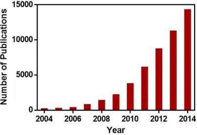
IGURESFigure 1.1 Number of publications regarding graphene based materials, in the last 10 years,
resulting from a literature review carried out using the database Scopus®. ...3
Figure 1.2 Structural representation of the single-walled nanotubes (SMWTs) and the multi-walled nanotubes (MWNTs) [10]. ...4
Figure 1.3 Representation of the two CNTs conformations: (a) armchair conformation and (b) zig-zag conformation [7]. ...5
Figure 1.4 Physical illustration of the graphite structure [25]. ...6
Figure 1.5 (a) Schematic representation of the graphene crystal structure; (b) Structural model of the pristine graphene lattice, where it is possible to observe the ripples presence [4]. ...8
Figure 1.6 two connect with each other [37]. ...9
Figure 1.7 Schematic representation of the unzipping of a SWNTs and consequent nanoribbon formation [54]. ... 11
Figure 1.8 Chemical structure of GO according to the model proposed by Lerf and Klinowski [44]. ... 12
Figure 1.9 Schematic representation of chitin chemical structure [75]. ... 14
Figure 1.10 Schematic representation of chitosan chemical structure [75]. ... 14
Figure 1.11 Chemical structure of alginate: M and G blocks [83]. ... 15
Figure 1.12 LbL dip coating assembly process representation with the different steps illustration. ... 19
Figure 2.1 Representation of the basic units (a) Si-O thetrahedron and (b) Al-O octahedron present on the clay minerals [43]. (c) Representation of the different structures resulted from different clay dispersion in the polymeric matrix. (i) Tactoid structures, (ii) intercalated structures and (iii) exfoliated structures [39]. ... 35
Figure 2.2 Schematic representation of (a) graphene and (b) graphene oxide sheet [90]... 40
Figure 2.3 (a) Schematic representation of the procedure to obtain a membrane/film using the solvent casting method (b) Comparison between the surface of a (i) CHI membrane and (ii) CHI/bioactive glass membrane [115], both obtained by solvent casting. ... 42
Figure 2.4 Representation of (a) three main LbL methods: (i) dip coating; (ii) spin coating and (iii) spray coating; and (b) Image of a chitosan/alginate free-standing membrane, where (i) represents the membrane obtained by dip coating a polypropylene substrate after 100 cycles and (ii) its respective cross-section SEM picture [128]. ... 44 Figure 2.5 Schematic illustration of the different structures resulted from the different building blocks and substrates used in the LbL process [129]. ... 44 Figure 2.6 (a) Representation of the different electrospinning approaches, namely (i) wet-dry spinning, (ii) wet-wet spinning and (iii) co-axial electrospinning. (b) Representation of a (i) macroscopic electrospun chitosan fibermat and (ii) chitosan/hydroxyapatite nanoparticles fibers morphology obtained by SEM with respective insert image at lower magification [135]. ... 46 Figure 3.1 Representation of the color changing along with the procedure evolution. (a) Magnetic stirring of the solution with EG and H2SO4 (solution completely black); (b) solution after adding
300 mL of DW (brownish solution) and (c) solution following the H202 adding (yellow solution).. 70
Figure 3.2 Schematic representation of the nanoribbons process. 1) Initial conformation of MWNTs;2) Manganate ester formation; 3) with further oxidation is possible to achieve the dione; 4) next to the ketones there is distorts of the , alkenes (red part), making them more prone to the next attack by permanganate. As the process continues, the strength ketones induce less strain on the , alkenes since there is more space for carbonyl projection, however the enlarging hole make them more reactive. The opening has been initiate and the ketones can be converted to carboxylic acid which will be responsible for the aligning of the nanoribbons edges; 5) the nanotube opens and originates the graphene ribbon [3]. ... 71 Figure 3.3 Schematic representation of the LbL processing. (a) Methodology used to produce
(CHI/ALG/CHI/o-GF)100 or (CHI/ALG/CHI/o-GNR)100 where 1 and 5: CHI solutions (2 mg/ml;
pH=5.5); 2, 4 and 6: washing solutions (DW; pH=5.5); 3: ALG solution (2 mg/ml; pH=5.5); 7: empty cup; 8: o-GF or o-GNR solutions (0.25 mg/ml; pH=8); 9: washing solutions (DW; pH=8).
(b) Methodology used to produce (CHI/ALG/CHI/ALG)100, where 1 and 5: CHI solutions (2 mg/ml;
pH=5.5); 2, 4 and 6: washing solutions (DW; pH=5.5); 3: ALG solution (2 mg/ml; pH=5.5); 7: empty cup; 8: ALG solution (2 mg/ml; pH=5.5); 9: washing solutions (DW; pH=5.5). ... 76 Figure 3.4 Schematic representation of AFM system [22]. ... 78 Figure 3.5 Schematic representation of contact angle measurements on a solid surface. (a) Hydrophobic surface; (b) and (c) hydrophilic surfaces [25]. ... 79
Figure 4.1 TGA thermograms of (a) o-EG and (b) o-MWNTs, under a heating rate of 10 °C/min; (c) and (d) are the Raman spectra obtained at 532 nm for o-EG and pristine EG and o-MWNTs and pristine MWNTs, respectively. ... 102 Figure 4.2 (a) UV-Vis spectra of o-GNR (black line) and o-GF (red line) aqueous solution at a concentration of 0.25 mg/mL. (b) FTIR spectra of dried o-GNR (black line) and o-GF (red line). ... 104
Figure 4.3 SEM images of (a1) upper side and (a2) substrate side of (CHI/ALG/CHI/ALG)100 FS;
(b1) upper side and (b2) substrate side of (CHI/ALG/CHI/o-GF)100 FS; (c1) upper side and (c2)
substrate side of (CHI/ALG/CHI/o-GNR)100 FS. The cross-section of each membrane is depicted on
(a3),(b3) and (c3)micrographs. ... 104
Figure 4.4 AFM surface images with respective 3D representation of: controls FS membranes (a;
a1), (CHI/ALG/CHI/o-GF)100 membranes (b; b1) and (CHI/ALG/CHI/o-GNR)100 membranes (c;
c1). (d) RRMS and (e) is the Hav). Significant differences were state for p < 0.001(***) and p <
0.0001(****). ... 108 Figure 4.5 (a,c) Distribution of o-GNR and o-GF (blue) in the polymeric matrix (CHI/ALG) obtained by Raman spectroscopy, with respective intensity color scale (a.u); (b,d) optical image of the o-GNR and o-GF composite membranes; (e,f) Raman spectra obtained for the o-o-GNR and o-GF before (black line) and after the dispersion (red line) in the (CHI/ALG) matrix, respectively. .... 109 Figure 4.6 TGA graphic representation (a) Thermogravimetric (TGA) curves with inset showing a magnification for the temperature range of 792.5-795 ºC and (b) Derivative of the weight loss curves (DTGA) for all membranes, as a function of temperature (ºC). ... 110 Figure 4.7 Water contact angle results with representative images for both sides of all membranes. Significant differences were state for p < 0.0001(****). ... 111
Figure 4.8. Variation of the water uptake ability as a function of time of (CHI/ALG/CHI/ALG)100
(black round symbol), (CHI/ALG/CHI/o-GF)100 (grey triangle symbol) and (CHI/ALG/CHI/o-GNR)100
(red square symbol) in PBS at 37 °C. ... 112
Figure 4.9 Degradation behavior of (CHI/ALG/CHI/ALG)100 (black round symbol),
(CHI/ALG/CHI/o-GF)100 (grey triangle symbol) and (CHI/ALG/CHI/o-GNR)100 (red square symbol)
Figure 4.10 DMA measurements. Variation of the Storage modulus (a) and the loss factor (b) along a frequency scan ranging from 0.1-15 Hz, at 37ºC of the FS membranes while immersed in PBS to closely simulate the physiological conditions. ... 114 Figure 4.11 Representation and comparison of mechanical properties of controls, GNR and
o-GF composite membranes. (a) Ultimate tensile strength (UTS) and (b) strain at break ( B).
Significant differences were found for p < 0.001(***) and p < 0.0001(****). ... 115
Figure 4.12 ology using DAPI for nuclei staining (blue labeled) and
phalloidin for F-actin filaments staining (red labeled) by fluorescence microscopy at 1, 3, and 7
days post-seeding on (CHI/ALG/CHI/ALG)100, (CHI/ALG/CHI/o-GNR)100 and (CHI/ALG/CHI/o-GF)100
FS membranes. ... 116
Figure 4.13 (a) Cellular viability analysis for (CHI/ALG/CHI/ALG)100, (CHI/ALG/CHI/o-GNR)100
and (CHI/ALG/CHI/o-GF)100 membranes using the MTS assay for 1,3 and 7 days. (b) DNA
quantification assay performed on (CHI/ALG/CHI/ALG)100, (CHI/ALG/CHI/o-GNR)100 and
(CHI/ALG/CHI/o-GF)100. Significant differences were found for < 0.05(*), < 0.01(**), <
0.001(***) and < 0.0001(****), N=3. ... 117
L
IST OFT
ABLESTable 1.1. Comparison between the different bottom-up techniques for membranes production. ... 18 Table 2.1. Chitosan based nanocomposites for different biomedical applications. ... 48
1. I
NTRODUCTIONThe aim of this chapter is to highlight the motivation of the work and to provide the essential information about the materials and production techniques adopted in this thesis.
1.1 Motivation
Could graphene become the material for the next disruptive technology, replacing some of the currently used materials and leading to new markets?[1] This question, mentioned by
Nosovelov in their paper about , is the main reason why we decided
to investigate this material. In fact, since 2004, when Novosolev and Geim successfully isolated and characterized a single sheet of graphene, the scientific research about this topic has increased exponentially (Figure 1.1) leading to new ways of graphene production suitable for mass fabrication [2, 3].
Figure 1.1 Number of publications regarding graphene based materials, in the last 10 years, resulting from a literature review carried out using the database Scopus®.
One of the most common methods of graphene production involves the chemical oxidation of carbon bulk materials such as, graphite and carbon nanotubes, resulting in graphene oxide. This form of graphene is notable for showing excellent aqueous processability, amphiphilicity, ease of surface functionalization, surface and fluorescence quenching ability, and thus revealing important features for biomedical applications [4]. The possibility to use this material as a filler, in particular of natural polymeric matrixes, is a practical approach to achieve nanocomposites with mechanical, optical, barrier and electronic potential [5].
Regarding the aforementioned information, the present work investigates the production of free-standing multilayered composite membranes, by assembling layers of graphene oxide and natural polymers, such as chitosan and alginate, through the layer-by-layer technique. Such membranes, which combine the advantages of graphene and those of natural polymers, such as biodegradability and biocompatibility, may find potential for several biomedical applications, namely for bone or cardiac regeneration.
1.2 Multi-walled Carbon Nanotubes (MWNTs) 1.2.1 Structure
Carbon nanotubes (CNTs), first brought to the attention of the scientific community by S. Iijima in 1991 [6], are seamless tubes of one or more layers of graphene rolled in a concentric way, with open or closed ends [7, 8]. Two major types of carbon nanotubes may be distinguished: the single-walled nanotubes (SWNTs), formed by a rolled single layer of graphene, with a diameter approximately of 1-2 nm; and the multi-walled nanotubes (MWNTs), which are an arrangement of concentric graphite cylinders, held together by secondary van der Walls bonding and separated from each other by 0.35 nm. The diameter of the MWNTs ranges typically from 5 to 20 nm and in some cases it can reach 100 nm, Figure 1.2 [8, 9].
Figure 1.2 Structural representation of the single-walled nanotubes (SMWTs) and the multi-walled nanotubes (MWNTs) [10].
The properties of nanotubes are affected by different parameters, particularly by: the geometry of the atomic arrangement relative to the nanotube axis direction (chirality), diameter, length and morphology. The nanotube chirality is the most influent feature on the CNTs properties,
affected by the chiral angle (amount of twists in the tube). The chiral angle can adopt different conformations from the zig-zag (chiral angle=0º) to the armchair conformation (chiral angle=30º), Figure 1.3. For angles between 0 and 30º the nanotubes are designed as chiral. Depending on this angle, the carbon nanotubes can be classified as metallic, semi-metallic or semi-conducting [9-11].
Figure 1.3 Representation of the two CNTs conformations: (a) armchair conformation and (b) zig-zag conformation [7].
1.2.2 Properties
Focusing on MWNTs, their electrical properties are typical of metallic materials, capable of
carry currents up to [12]. Mechanically, they have shown an elastic modulus reaching 1
TPa and a tensile strength of 63 GPa [13]. Besides, they present a density near 1.74 g. and
in ideal conditions, where the carbon lattice does not exhibit any defect, the MWNTs are able of a
ballistic electron transport. A room temperature thermal conductivity up to 6000 W. has
been predicted, which is twice as high as diamond [14-17].
MWNTs can be synthetized through different methods, namely: arc-discharge, laser ablation, gas-phase catalytic growth and chemical vapor deposition (CVD) [7, 18, 19]. Among all these techniques, CVD is the most used industrial procedure, once it reveals to be a cost-effective process [20]. However, the MWNTs formed by this method generally present some lattice defects, influencing several physical properties, such as: thermal, mechanical and electronic [9].
Since 1994, after Ajayan used CNTs as a polymer fillers [21], different applications
have been investigated using MWNTs. For instance, Shin demonstrated to achieve functional
cardiac patches, to replace damaged heart tissue, by seeding neonatal cardiomyocites onto MWNTs, incorporated into photo-cross linkable gelatin methacrylate [22]. The electrical
conductivity of the CNTs, as well as, the nanofibrous network formed with the gelatin network, resulted in a patch with enhanced cardiac cell adhesion, excellent mechanical integrity and electrophysiological functions [22]. Other applications have been explored, such as the work done
by Holy [23], where pluripotent P19 mouse embryonal carcinoma stem cells were seeded
onto cell culture glass coverslips coated with MWNTs thin films, using layer-by-layer technique. The cells were either maintained in an undifferentiated state or induced to differentiate by the addition of retinoic acid. The results indicated that the cell adhesion was increased on the MWNTs-coated glass surface and it may facilitate neuronal differentiation of P19 stem cells [23].
1.3 Graphite 1.3.1 Structure
Graphite is a three-dimensional (3D) layered crystal, Figure 1.4, made of stacked parallel graphene sheets that may occur in two different crystal phases: hexagonal and rhombohedral [24].
Typically, the orbitals are bonded in a hexagonal network and the graphene sheets are
separated from each other by 0.335 nm [25]. Due to the orbitals of the carbon atoms that overlap each other, the lowest energy is obtained when the graphene sheet is completely flat. Graphite is anisotropic due to the differences in the bonding of the carbon atoms in the in-plane and out-of-plane dimensions [25].
Figure 1.4 Physical illustration of the graphite structure [25].
The carbon bonding in the graphite structure is covalent between the carbon atoms in the in-plane dimension, and based on weak van der Waals forces in the inter-planar area, keeping together the graphene sheets. In fact, these non-covalent interactions allows the graphene sheets
to slide one over the other, giving to the graphite a soft and lubricating character, as well as its most known feature, the ability to mark paper [25, 26].
1.3.2 Properties
Regarding its mechanical properties, graphite is characterized by a high elastic modulus, 1TPa for the in-plane directions, and a good strength value, approximately 130 GPa. It presents a
thermal conductivity of 3000 and an electrical character along the basal planes with a
resistivity of 50 µ .cm. At the same time, graphite acts as an insulator, perpendicular to the basal planes, being for that, alternatively considered a semi-metal or a zero-gap semiconductor [27-29]. Regarding the production of nanocomposites, high aspect ratio materials are desirable. For that, new methodologies to achieve graphite structures with few layers separated down to a nanometer thickness, presenting high aspect ratio and high modulus, were investigated leading to the production of exfoliated graphite (EG). This type of graphite is produced by separation of the graphite layers through intercalation of alkali metals followed by exfoliation with aqueous solvents [30, 31].
Taking into consideration all these characteristics, graphite has been investigated for varied
applications. For instance, Shen have developed electrically conductive nanocomposites
based on maleic anhydride grafted polypropylene (gPP) and EG [32]. Zanni assessed the
toxicity and antimicrobial properties of graphite, using the model organism Caenorhabditis elegans where the absence of any acute or chronic toxicity was verified [33].
1.4 Graphene 1.4.1 Structure
is one of the allotropes of elemental carbon and, in 1960 [34], it was defined as the higher conductive basal plane in the graphite structure.
This material is a monolayer of bonded carbon atoms arranged into a two-dimensional
(2D) honeycomb like-structure, with a carbon-carbon bond length bond of 0.142 nm, Figure 1.5 a) [35].
Figure 1.5 (a) Schematic representation of the graphene crystal structure; (b) Structural model of the pristine graphene lattice, where it is possible to observe the ripples presence [4].
The graphene lattice may be described by two sub-lattices of bonded carbon, where each [36]. In fact, the chemical boding of graphene can be explained through the benzene molecule, which consists of a hexagon with bonded carbons atoms in the vertices. Each carbon atom is also covalently bonded with hydrogen atoms that stick out from the hexagon in a star-like shape. In addition to the six
bonds there are three bonds created by the orbitals. The result is a hexagon structure with
alternate bonds. So, graphene may be seen as a benzene-type of structure where the hydrogen atoms are replaced by carbon atoms forming a continuous network of carbon hexagons [37].
One of the most interesting features shown by this material is the van der Waals thickness of a graphene sheet (0.34 nm), making it the thinnest 2D filler known to date [38]. According to transmission electron microscopy (TEM) studies, another structural characteristic that should be highlight is the existence of intrinsic ripples, Figure 1.5 b), which are extremely important, as they influence the graphene properties such as electrical and optical [39].
1.4.2 Properties
As consequence of its structure, graphene presents exceptional mechanical, electrical and thermal properties. It has a high elastic modulus of approximately 1 TPa, the highest known
intrinsic electrical conductivity of 6 105 S.m-1 and the high thermal conductivity of 5.1
[1, 40, 41].
The outstanding electrical and thermal properties are related with the high mobility of the level, situated at the Dirac Points,
conductive [5, 37, 42]. Besides, graphene also shows a large theoretical specific area of 2630 , an optical transmittance of 97.7% and a high flexibility [36, 43].
Figure 1.6
as well as the Fermi level where these two connect with each other [37].
1.5 Production Techniques
Currently there is a wide number of methods that may be used to produce graphene with various dimensions, shapes and qualities. In general, these methods fall into five main groups:
(i) Mechanical exfoliation of a single sheet of graphene from bulk graphite, also known as This technique is a simple peeling process of commercially available graphite that originates thin flakes, which are composed of a monolayer or a few layers of graphene. This process has often demonstrated a low probability to achieve individual graphene sheets [44].
(ii) Chemical vapor deposition (CVD)
This is the most promising technique reported to be capable of producing mono- or few-layer graphene films [44]. A typical CVD process uses a carbon rich gas precursor, such as methane, which is dissolved on the surface of a metal foil (cooper (Cu) or nickel (Ni)) under inert atmosphere and high temperature. Typically the metal substrate is placed in the CVD chamber at 1000º C with a diluted hydrocarbon gas. The incorporation of the carbon atoms into the metal foil starts and after that a rapid cooling process takes place causing an out-diffusion of the carbon atoms to the metal surface [1, 45]. By controlling parameters such as the temperature, and the substrate, single or double layers of graphene can be obtained [38]. However there are some drawbacks such as
the large energy consumption, the defects on grain boundaries and those caused by the removal
of the underlying metal, as well as [1].
(iii) Epitaxial growth of graphene films from silicon carbide (SiC)
Silicon carbide (SiC) is a common material used for high power electronics and because of that, this technique has been an attractive approach for the electronic field, since it does not require the removal of the underlying substrate. This method uses ultrahigh vacuum (UHV), which when applied to the SiC wafer induces the sublimation of the silicon (Si) atoms, resulting in a graphitized surface. Still, there are some issues with this technique, namely the high cost of the SiC wafers, the high temperature used (above 1000°C) and the small size of the wafers [46, 47].
(iv) Exfoliating graphite towards graphene
This top-down production method may be achieved through two different processes, namely: solution based exfoliation of graphite intercalation compounds (GICs) and chemical oxidation/exfoliation of graphite to graphene oxide (GO) followed by reduction of graphene oxide
(rGO) [48]. Regarding the last one, it was first described by Brodie [49], in 1859, and since
then several changes were made regarding the concentration and types of oxidants agents used [40, 49]. Currently, the most popular method for the production of GO is based on the modifications introduced by Hummers and Offeman in 1958 [50], which consists in the oxidation of graphite by a harsh treatment. The oxidation is carried out by combining graphite powder in sulfuric acid
( )concentrated solution, containing potassium permanganate ( ) and sodium nitrate
( ) in the weight proportion of 1:1:3:0.5. When compared to previous methods, this
methodology displays the advantage of lower explosion risk and good efficiency [50, 51]. However
there is still the drawback of toxic gas release and existence of sodium ions ( )and nitrate ions
( ), which are difficult to remove from the solution [51].
In order to overcome these limitations
developed, where the was replaced by increasing the amount of , allowing to
increase the reaction yield and reduce the toxic gas production [40]. Therefore, this method was chosen to produce the GO used in this work. Due to the structural defects generated during the chemical reaction, the electronic structure of graphene is disrupted. In order to recover this feature, chemical or physical reduction of GO is usually applied [36, 52].
(v) Longitudinal unzipping of carbon nanotubes
Different approaches have been performed and developed to obtained graphene nanoribbons from CNTs. Two approaches have been explored for this top-down synthesis, namely: (i) the cutting or etching of graphene or graphite precursors into narrow graphene strips and (ii) the longitudinal unzipping of CNTs [48].
As example of the first methodology is the work performed by Day [53] where they
embedded MWNTs in a poly(methyl methacrylate) (PMMA) film. This film (MWNT-PMMA) was etched by argon plasma and then, in order to remove the polymeric part, solvent vapor was used [53].
The methodology used in this work consisted on the extensive oxidation of carbon nanotubes
until their unzipping is achieved. Typically, a chemical attack performed by and at
room temperature, followed by a mild heating treatment allows to unzip the CNTs longitudinally. It should be noticed that different opening routes may occur, such as longitudinally or in a spiraling way. These opening mechanisms are dependent of the initial site attack as well as of the chiral angle of CNTs. Although the unzipping was depicted by the authors as starting at one specific point and continuing along the CNTs, Figure 1.7, in fact the CNT wall is extensively oxidized, and it
appears that manganate ions ( ) has a catalyst action upon breaking the C-C bonds along the
CNT length [54]. As result of the opening process, an oxidized graphene nanoribbon-like structure (o-GNR) is obtained with high water and organic solvents solubility [54]. A further detailed analyses of the opening mechanism is described on the Materials and Methods section.
Figure 1.7 Schematic representation of the unzipping of a SWNTs and consequent nanoribbon formation [54].
Although the routes (i),(ii) and (iii) may be preferred for devices that require high quality graphene, due to the quality of the produced graphene, the techniques (iv) and (v) are more attractive for large scale manufacturing, once they represent a scalable possibility to obtain high
volume production and at the same time a versatile technique, in terms of being well suited for chemical functionalization [55].
1.6 Graphene Oxide (GO)
Graphene oxide (GO) is a graphene derivative that has been widely used as an alternative or as a precursor of graphene [38]. A wide number of chemical models have been proposed to describe GO structure
known - the Lerf and Klinowski mode Figure 1.8. In this model, hydroxyl and epoxy groups are present on both sides of the basal plane, and carbonyl along with carboxyl acids are distributed in the sheet edges [44]. These containing oxygen groups render GO a biocompatibility and physiological solubility behavior [56].
Figure 1.8 Chemical structure of GO according to the model proposed by Lerf and Klinowski [44].
Usually the carbon:oxygen ratio is approximately 2:1 and the oxidized regions can reach up to 70% [44, 57, 58]. This material shows a negative charge in acidic or basic environments, largely due to the carboxyl groups, and the zeta potential is able to reach values in the order of -50 mV for a pH=10.5 [59].
Commonly, GO is described as a hydrophilic carbon material, however recent works suggests GO as an amphiphilic material, once it may present a hydrophobic and hydrophilic domain, depending on the surface region and extent of oxidation [38, 60].
Regarding its mechanical properties, a decrease is observed when compared to graphene, although GO stills exhibit good properties, such as an elastic modulus of 250 GPa and extreme flexibility [61]. One of the major drawbacks caused by the oxidation process is the damage of the hybridization and consequently lack in the conductive character shown by graphene. Although not performed in this work, this damage may be partially repaired through a reduction process using hydrazine, among other reducing agents [36, 52].
properties. The interfacial interactions between these materials may be of diverse nature, including: covalent bonding; polymers with a carboxyl terminated groups that can crosslink with GO hydroxyl groups through esterification; electrostatic interactions; and hydrogen bonding between highly polarized donor and acceptors, which are extremely abundant in GO due to its epoxy, hydroxyl, carboxyl and carbonyl groups. Because of that GO can bond with different polar polymers. Depending on the bonding characteristics, different mechanical response may be observed in the composite materials formed [38, 62].
1.7 Natural Polymers
Polymers and more specifically polymeric biomaterials have been investigated and used for health care applications for a long time [63]. A biomaterial is defined as a natural or synthetic material engineered to interface with biological systems to evaluate, treat, augment or replace any type of tissue, organ or function of the body [64, 65].
Regarding natural polymers, it is possible to distinguish three different types: proteins, such as gelatin and collagen; polysaccharides, where it is possible to find materials such as chitosan and alginate; and finally polynucleotides, where it is worth to highlight DNA and RNA [66].
Despite of the material selected, there is an essential prerequisite that needs to be present to classify the material as a biomaterial, the biocompatibility. This feature means that the biomaterial should have the ability to perform its function with an appropriate host response for the desired application [65, 67]. In fact, natural polymers are known for being extremely similar to macromolecular substances which are recognized by the biological environment, and so, the natural polymers are metabolically eliminated. This similarity suppress problems such as toxicity and chronic inflammation reactions, which are related with synthetic polymers. However, one of the main disadvantages of natural polymers is the low processing ability when compared to the synthetic ones, limiting their applications [66].
1.7.1 Chitosan
Chitosan (CHI) is a linear and semi-crystalline polysaccharide obtained from the deacetylation of the natural polymer named chitin (Figure 1.9) by chemical hydrolysis under alkaline conditions or by enzymatic hydrolysis, such as, chitin deacetylase [68]. Apart from cellulose, chitin is the most common biopolymer in the nature, being present in biological structures like: exoskeleton of crustaceans and insects, and also in some fungi cell walls [69-71].
CHI has two allomorphs forms: namely and forms, being the first form the most abundant in nature [69, 72].
Identified in 1884, the chemical structure of CHI is composed of glucosamine (2-amino-2-deoxy- -D-glucan) and -acetyl glucosamine (2-acetamido-2-(2-amino-2-deoxy- -D-glucan) units bonded by
(1 4) glycosidic linkage, Figure 1.10 [69, 73]. The glucosamine amount present in chitin structure reveals its deacetylation degree (DD), and in fact chitin becomes soluble in aqueous acidic conditions when this amount is higher than 60%, being named chitosan. In addition, the DD is responsible for some of the main characteristics presented by CHI, including crystallinity, molecular weight and biological properties [74].
Figure 1.9 Schematic representation of chitin chemical structure [75].
Figure 1.10 Schematic representation of chitosan chemical structure [75].
Taking into considerations the previous figures, it is possible to observe that the main difference between both structures, is the presence of the amino groups in CHI. In fact, this group is responsible for the solubility in acidic solutions (pH<6), once it might be protonated and its pKa is 6.3 [76]. This protonation gives CHI a polycationic character allowing it to form ionic complexes with a wide range of synthetic and natural anionic polymers, including alginate [77].
This material has been extensively investigated for healthcare applications, due to the antibacterial, antifungal, mucoadhesive, analgesic and haemostatic activity [73, 75, 78, 79].
presented results an excellent blood compatibility was achieved, with a lower blood loss and faster degradation than gelatin sponges, showing a promising potential for application of these as
hemostatic sponges [80]. Zhang using electrospun nanofibers of hydroxyapatite and CHI,
demonstrated to be possible to stimulate the bone formation, once it was shown cell proliferation and mineral deposition [81].
1.7.2 Alginates
Alginates (ALG) are natural polysaccharides extracted from various species of brown
seaweed ( ) or provide by bacterial biosynthesis, such as Pseudomonas aeruginosa
[82]. Although ALG obtained from bacterial sources are more chemically and physically well-defined than the ones obtained from brown algae, currently the most common source of ALG comes from this last type of organisms [83, 84]. The extraction from algae can be achieved through a treatment with alkali solution, such as sodium hydroxide (NaOH), followed by a filtration process and precipitation with sodium chloride (NaCl). The purification process, realized with hydrochloric acid (HCl) treatment leads to production of alginic acid which can be converted to salt, ending in a water-soluble sodium alginate powder [84].
The structure of ALG, first reported by Haug in 1966 [85], consists in a soluble fraction
composed exclusively of -D-mannurate (M-blocks) or -L-guluronate (G-blocks) monomers covalently linked through a glycoside bond (1 4), and in an insoluble part made of alternating M and G residues-Figure 1.11 [83, 86]. It is believed that the G-block length and molecular weight are critical factors that will influence the physical and mechanical properties of ALG. For instance, the high concentration of G-blocks in ALG chain leads to higher stiffness [87]. On the other hand when the amount of M-blocks is higher than G-blocks, the material will be weaker but more flexible [88].
Due to the abundance of algae in the nature, ALG can be obtained from different species which will differ in the content and length of each block. The obtained copolymer composition as well as the sequence and molecular weight of the obtained ALG will be dependent of the specie that produce the copolymer. Currently being produced more than 200 different ALG [83, 89].
ALG are hydrophilic polysaccharides that for a pH value above pKa M-blocks and G-blocks (3.38 and 3.65, respectively) are polyanions, due to the negative charge of the carboxylic groups [88]. It is a biocompatible and non-immunogenic material, not inducing any significant inflammatory reaction when implanted in animals, and capable to absorb water 200-300 times of its own weight [90, 91]. One of the main disadvantages of these materials it is its poor biodegradability, once alginase, an enzyme responsible for the degradation process, is not present in human beings or any other mammals [84].
Regarding the above characteristics, ALG have been widely investigated for biomedical
applications. Caridade . has proved to be possible to achieve free-standing membranes, based
in ALG and CHI with enhanced permeability and biocompatibility essential for tissue engineering applications [92]. More recently it was shown that the mentioned membranes could be used for bone defects applications when cross-linked with 1-ethyl-3-(3-dimethylaminopropyl)carbodiimide hydrochloride (EDC) since they were able to induce skeletal myoblasts proliferation and differentiate into myotubes. It was also verified that, when loaded with bone morphogenetic protein 2 (BMP-2), the membranes release the growth factor over 1 month providing an osteoinduction effect [93]. 1.8 Processing Techniques for Free-Standing Membranes
Commonly, 2D multilayer membranes are made from the adsorption of layers to an underlying substrate. However, one of the major weaknesses of this technique is the impossibility to remove them without any kind of damage [94]. The need to achieve untainted membranes resulted in the development of free-standing (FS) membranes.
FS membranes are consequence of a detachment from the underlying substrate without using any kind of method to remove them, and with the ability to maintain its shape and integrity. In fact, the key factor to obtain these membranes relies on the type of substrate used. Two different types may be chosen: sacrificial templates that will be dissolved by the solvents; or low-energy substrates, such as the polypropylene (PP) substrates used in this work. The latter was first
1.8.1 Layer-by-Layer (LbL) Assembly
Different approaches have been reported to obtain membranes, namely: the Langmuir-Blodgett (LB) technique, the self-assembled monolayer (SAM) method, and the layer-by-layer (LbL) process. The last has emerged as an important bottom-up process for surface engineering strategies, once it offers a reliable, easy, versatile and cost effective technique, among other advantages when compared to the LB and SAM methods -Table 1.1 [96].
The LbL assembling, first introduced in 1966 by Iler [97] and later expanded by Decher [98, 99], consists in a sequential adsorption of oppositely charged materials (including polycations and polyanions) on a substrate surface, via electrostatic or non-electrostatic, which includes hydrophobic interactions, hydrogen bonds and van der Walls forces [100]. Typically, a solid support with a negative charge is incubated in the solution containing polycations and a layer is adsorbed (Figure 1.12, step 1). Once the adsorption is carried out at high concentration, the surface charge is effectively reversed. The supports are then rinsed in a washing solution to remove the excess of free polyions and then are immersed in an anionic solution, being the original charge restored (Figure 1.12, step 2). This cycles are repeated until the desired number of layers (Figure 1.12, step 3). Then, (Figure 1.12, step 4) due to the weak van der Walls interactions, the membrane detaches from the substrate, resulting in a FS membrane, step 5 [101].
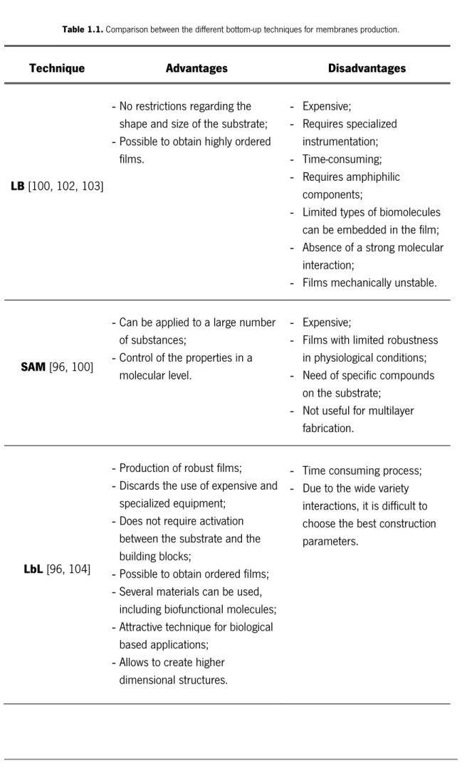
Table 1.1. Comparison between the different bottom-up techniques for membranes production.
Technique Advantages Disadvantages
LB [100, 102, 103]
- No restrictions regarding the shape and size of the substrate; - Possible to obtain highly ordered
films. - Expensive; - Requires specialized instrumentation; - Time-consuming; - Requires amphiphilic components;
- Limited types of biomolecules can be embedded in the film; - Absence of a strong molecular
interaction;
- Films mechanically unstable.
SAM [96, 100]
- Can be applied to a large number of substances;
- Control of the properties in a molecular level.
- Expensive;
- Films with limited robustness in physiological conditions; - Need of specific compounds
on the substrate; - Not useful for multilayer
fabrication.
LbL [96, 104]
- Production of robust films; - Discards the use of expensive and
specialized equipment; - Does not require activation
between the substrate and the building blocks;
- Possible to obtain ordered films; - Several materials can be used,
including biofunctional molecules; - Attractive technique for biological
based applications; - Allows to create higher
dimensional structures.
- Time consuming process; - Due to the wide variety
interactions, it is difficult to choose the best construction parameters.
Figure 1.12 LbL dip coating assembly process representation with the different steps illustration.
Even though it is a very simple process, a wide number of parameters affect the assembly of the layers. Starting with the drying steps during the process, it was demonstrated that the thickness of the adsorbed film increases, mainly due to the higher surface roughness arising from the drying. On the other hand, the washing steps between each adsorption are extremely important once it will remove the loosely attached material, and only the effective adsorption stays in the film, fomenting a successful adsorption and a stable film. The temperature is also an important factor, once for higher temperatures, the mobility of the adsorbed molecules is higher and the chances of finding better binding sites is greater [96].
Regarding the intrinsic properties of the polyelectrolytes (PE) solutions, the pH revealed to be extremely important once it varies the protonation state of the ionizable groups and because of that, the availability of the charged groups is altered [96]. The ionic strength also plays a significant role, especially in the membranes thickness. This feature can be tuned with the amount of salt added to the PE, which in turn induces the contraction of the PE with formation of compact globules of reduced net charge resulting in enhanced LbL assembly [103]. PE length ratio, the interaction between the PE chains, the PE concentration and the coexisting electrolyte species are moreover parameters to be taken into consideration [101].
The LbL ability to taylor the physico-chemical properties as well as the structure of different materials has opened new possibilities in different application, such as: biosensing, bioelectronics, drug and gene delivery, food industrialization, cell adesion/differentiation, proliferation, and tissue engineering. Regarding the LBL assembly of different polymers with graphene, a considerable amount of bibliography has been published [105-112]. This possibility was also explored by Shin and co-workers [113], who investigated a 3D tissue construction by alternative cell-seeding and
(poly(L-Lysine) (PLL) and GO deposition. By starting the membranes with a stable and homogeneous layer of 3T3 fibroblasts followed by PLL/GO deposition, it was shown to be possible to achieve a multilayer tissue where each cell layer was strongly attached due to the PLL/GO layer. These authors also have shown the possibility to obtain a spontaneous beating by replacing the
3T3 fibroblasts for a cardiomyocytes layer. Further, Yu studied the formation of graphene and
carbon nanotubes films for energy-storage applications [114]. Using the LbL process, layers of graphene grafted with poly(ethyleneimine) (PEI) were assembled with carbon nanotubes, resulting in multilayer films with a uniform network structure and well defined nanoscale pores which could serve as a fast electronic and ionic conducting channels, offering electrodes for energy store devices [114].
Bearing in mind the topic of this work, where FS membranes were obtained using the LbL technique, it is important to highlight that no scientific publications were found where CHI and ALG together with graphene based materials were assembled, through LbL, to originate FS membranes.
Besides, to the best of our knowledge, only the work of Wang explored the production
of FS membranes with GO and CHI, although using a vacuum filtration method, where it was found great mechanical and electrical improvements [115]. Comparing this work with the one developed on this thesis, significant differences were performed, namely, besides CHI and GO we also used ALG, and we produced the FS membranes using only the LbL technique.
1.9 Final Remarks
The possibility to achieve devices with improved targeting, mechanical, and electrical features and, at the same time, with biocompatible and potential regeneration behavior has resulted in the development of promissing materials to be further applicable to human situations. Nowadays, one of the major challenges in this field relies on the development of green and more environmental friendly procedures not only to produce graphene, but also to reduce the graphene oxide and restore the electrical behavior. In fact, these ambitious goals have suffered significant improvements in the last few years.
Despite the extensive research about this topic, it is important to notice that, although some information about graphene and GO membranes obtained by LbL has been published, this is not the case of free-standing membranes based on these materials, making this research work extremely valuable. In order to fully understand the great potential to use nanocomposites in the
biomedical field, a review of the state of the art of chitosan-based nanocomposites, including nanocomposites with graphene and GO, among others, will be presented in the next chapter.
1.10 References
[1] Novoselov KS, Fal'ko VI, Colombo L, Gellert PR, Schwab MG, Kim K. A roadmap for graphene. Nature. 2012;490:192-200.
[2] Novoselov KS, Geim AK, Morozov SV, Jiang D, Zhang Y, Dubonos SV, et al. Electric field effect in atomically thin carbon films. Science. 2004;306:666-9.
[3] Bitounis D, Ali-Boucetta H, Hong BH, Min DH, Kostarelos K. Prospects and Challenges of Graphene in Biomedical Applications. Advanced Materials. 2013;25:2258-68.
[4] Shao YY, Wang J, Wu H, Liu J, Aksay IA, Lin YH. Graphene Based Electrochemical Sensors and Biosensors: A Review. Electroanalysis. 2010;22:1027-36.
[5] Wang Y, Li ZH, Wang J, Li JH, Lin YH. Graphene and graphene oxide: biofunctionalization and applications in biotechnology. Trends in Biotechnology. 2011;29:205-12.
[6] Iijima S. Helical microtubules of graphitic carbon. Nature. 1991;354:56-8.
[7] Thostenson ET, Ren ZF, Chou TW. Advances in the science and technology of carbon nanotubes and their composites: a review. Composites Science and Technology. 2001;61:1899-912. [8] De Volder MFL, Tawfick SH, Baughman RH, Hart AJ. Carbon Nanotubes: Present and Future Commercial Applications. Science. 2013;339:535-9.
[9] Coleman JN, Khan U, Blau WJ, Gun'ko YK. Small but strong: A review of the mechanical properties of carbon nanotube-polymer composites. Carbon. 2006;44:1624-52.
[10] Farsi M, Sani FM. Effects of multi-walled carbon nanotubes on the physical and mechanical properties of high-density polyethylene/wood flour nanocomposites. Journal of Thermoplastic Composite Materials. 2014;27:1139-54.
[11] Jones DEH. Science of fullerenes and carbon nanotubes - Dresselhaus,MS, Dresselhaus,G, Eklund,PC. Nature. 1996;381:384.
[12] Wei BQ, Vajtai R, Ajayan PM. Reliability and current carrying capacity of carbon nanotubes. Applied Physics Letters. 2001;79:1172-4.
[13] Yu MF, Lourie O, Dyer MJ, Moloni K, Kelly TF, Ruoff RS. Strength and breaking mechanism of multiwalled carbon nanotubes under tensile load. Science. 2000;287:637-40.
[14] Che JW, Cagin T, Goddard WA. Thermal conductivity of carbon nanotubes. Nanotechnology. 2000;11:65-9.
[15] Osman MA, Srivastava D. Temperature dependence of the thermal conductivity of single-wall carbon nanotubes. Nanotechnology. 2001;12:21-4.
[16] Berber S, Kwon YK, Tomanek D. Unusually high thermal conductivity of carbon nanotubes. Physical Review Letters. 2000;84:4613-6.
[17] Collins PG, Avouris P. Nanotubes for electronics. Scientific American. 2000;283:62.
[18] Journet C, Maser WK, Bernier P, Loiseau A, delaChapelle ML, Lefrant S, et al. Large-scale production of single-walled carbon nanotubes by the electric-arc technique. Nature. 1997;388:756-8.
[19] Nikolaev P, Bronikowski MJ, Bradley RK, Rohmund F, Colbert DT, Smith KA, et al. Gas-phase catalytic growth of single-walled carbon nanotubes from carbon monoxide. Chemical Physics Letters. 1999;313:91-7.
[20] Lehman JH, Terrones M, Mansfield E, Hurst KE, Meunier V. Evaluating the characteristics of multiwall carbon nanotubes. Carbon. 2011;49:2581-602.
[21] Ajayan PM, Iijima S. Capillarity-induced filling of carbon nanotubes. Nature. 1993;361:333-4. [22] Shin SR, Jung SM, Zalabany M, Kim K, Zorlutuna P, Kim SB, et al. Carbon-Nanotube-Embedded Hydrogel Sheets for Engineering Cardiac Constructs and Bioactuators. Acs Nano. 2013;7:2369-80.
[23] Holy J, Perkins E, Yu X. Adhesion, proliferation and differentiation of pluripotent stem cells on multi-walled carbon nanotubes. Iet Nanobiotechnology. 2011;5:41-6.
[24] Ooi N, Rairkar A, Adams JB. Density functional study of graphite bulk and surface properties. Carbon. 2006;44:231-42.
[25] Sengupta R, Bhattacharya M, Bandyopadhyay S, Bhowmick AK. A review on the mechanical and electrical properties of graphite and modified graphite reinforced polymer composites. Progress in Polymer Science. 2011;36:638-70.
[26] Mao WL, Mao HK, Eng PJ, Trainor TP, Newville M, Kao CC, et al. Bonding changes in compressed superhard graphite. Science. 2003;302:425-7.
[27] Endo Y. Advanced composite materials & technology for aerospace application. Sen-I Gakkaishi. 2004;60:P298-P304.
[28] Xie XL, Mai YW, Zhou XP. Dispersion and alignment of carbon nanotubes in polymer matrix: A review. Materials Science & Engineering R-Reports. 2005;49:89-112.
[29] Schadler LS. Polymer-based and Polymer-filled Nanocomposites. In: KGaA W-VVGC, editor. Nanocomposite Science and Technology. Weinheim2003. p. 77-153.
[30] Viculis LM, Mack JJ, Mayer OM, Hahn HT, Kaner RB. Intercalation and exfoliation routes to graphite nanoplatelets. Journal of Materials Chemistry. 2005;15:974-8.
[31] Yasmin A, Luo JJ, Daniel IM. Processing of expanded graphite reinforced polymer nanocomposites. Composites Science and Technology. 2006;66:1182-9.
[32] Shen JW, Chen XM, Huang WY. Structure and electrical properties of grafted polypropylene/graphite nanocomposites prepared by solution intercalation. Journal of Applied Polymer Science. 2003;88:1864-9.
[33] Zanni E, De Bellis G, Bracciale MP, Broggi A, Santarelli ML, Sarto MS, et al. Graphite Nanoplatelets and Caenorhabditis elegans: Insights from an in Vivo Model. Nano Letters. 2012;12:2740-4.
[34] Singh V, Joung D, Zhai L, Das S, Khondaker SI, Seal S. Graphene based materials: Past, present and future. Progress in Materials Science. 2011;56:1178-271.
[35] Slonczewski JC, Weiss PR. Band structure of graphite. Physical Review. 1958;109:272-9. [36] Zhu YW, Murali S, Cai WW, Li XS, Suk JW, Potts JR, et al. Graphene and Graphene Oxide: Synthesis, Properties, and Applications. Advanced Materials. 2010;22:3906-24.
[37] Goerbig MO. Electronic properties of graphene in a strong magnetic field. Reviews of Modern Physics. 2011;83:1193-243.
[38] Hu KS, Kulkarni DD, Choi I, Tsukruk VV. Graphene-polymer nanocomposites for structural and functional applications. Progress in Polymer Science. 2014;39:1934-72.
[39] Meyer JC, Geim AK, Katsnelson MI, Novoselov KS, Booth TJ, Roth S. The structure of suspended graphene sheets. Nature. 2007;446:60-3.
[40] Chen J, Yao BW, Li C, Shi GQ. An improved Hummers method for eco-friendly synthesis of graphene oxide. Carbon. 2013;64:225-9.
[41] Mayorov AS, Gorbachev RV, Morozov SV, Britnell L, Jalil R, Ponomarenko LA, et al. Micrometer-Scale Ballistic Transport in Encapsulated Graphene at Room Temperature. Nano Letters. 2011;11:2396-9.
[42] Zhang YB, Tan YW, Stormer HL, Kim P. Experimental observation of the quantum Hall effect and Berry's phase in graphene. Nature. 2005;438:201-4.
[43] Nair RR, Blake P, Grigorenko AN, Novoselov KS, Booth TJ, Stauber T, et al. Fine structure constant defines visual transparency of graphene. Science. 2008;320:1308.
[44] Compton OC, Nguyen ST. Graphene Oxide, Highly Reduced Graphene Oxide, and Graphene: Versatile Building Blocks for Carbon-Based Materials. Small. 2010;6:711-23.
![Figure 1.2 Structural representation of the single-walled nanotubes (SMWTs) and the multi-walled nanotubes (MWNTs) [10]](https://thumb-eu.123doks.com/thumbv2/123dok_br/17614003.820440/23.892.289.603.698.946/figure-structural-representation-single-walled-nanotubes-smwts-nanotubes.webp)
![Figure 1.3 Representation of the two CNTs conformations: (a) armchair conformation and (b) zig-zag conformation [7]](https://thumb-eu.123doks.com/thumbv2/123dok_br/17614003.820440/24.892.298.589.288.529/figure-representation-cnts-conformations-armchair-conformation-zig-conformation.webp)
![Figure 1.4 Physical illustration of the graphite structure [25].](https://thumb-eu.123doks.com/thumbv2/123dok_br/17614003.820440/25.892.339.563.729.955/figure-physical-illustration-graphite-structure.webp)
![Figure 1.7 Schematic representation of the unzipping of a SWNTs and consequent nanoribbon formation [54]](https://thumb-eu.123doks.com/thumbv2/123dok_br/17614003.820440/30.892.256.638.784.971/figure-schematic-representation-unzipping-swnts-consequent-nanoribbon-formation.webp)
![Figure 1.8 Chemical structure of GO according to the model proposed by Lerf and Klinowski [44]](https://thumb-eu.123doks.com/thumbv2/123dok_br/17614003.820440/31.892.208.679.496.598/figure-chemical-structure-according-model-proposed-lerf-klinowski.webp)
![Figure 1.10 Schematic representation of chitosan chemical structure [75].](https://thumb-eu.123doks.com/thumbv2/123dok_br/17614003.820440/33.892.255.637.673.808/figure-schematic-representation-chitosan-chemical-structure.webp)

![Figure 2.1 Representation of the basic units (a) Si-O thetrahedron and (b) Al-O octahedron present on the clay minerals [43]](https://thumb-eu.123doks.com/thumbv2/123dok_br/17614003.820440/54.892.214.686.118.437/figure-representation-basic-units-thetrahedron-octahedron-present-minerals.webp)
