ICAD-2009-XX
ABSTRACT
Nowadays, due to its critical role regarding product cost and performance, as well as, time to market, product design is considered to be at the new frontiers for achieving competitive advantage. Therefore, to face today’s rapidly changing business environments, it is extremely important to adopt a systematic approach to product design, in order to avoid errors and consequently achieve shorter time-to market performances. In this context, we will describe a new approach to support product design, which links Axiomatic Design (AD) and Multidisciplinary Design Optimization (MDO), applied in an integrated way at the conceptual design and the detailed design stages, respectively. Firstly, the conceptual design stage is undertaken by AD, which is used to map Functional Requirements (FRs) with the corresponding Design Parameters (DPs). Even though we try to guarantee the Independence of FRs, as established by Axiom 1 of AD, if some remaining coupled relations subsist that is not prohibitive. Afterwards, the detailed design is carried out by MDO, considered to be an appropriate methodology to design complex systems through an adequate exploitation of interacting phenomena. The proposed approach is applied to the design of metallic moulds for plastic parts injection, since the mould makers sector involves constant design and production of unrepeatable moulds, where uncoupled designs solutions, mostly due to technological and time reasons, aren’t common (this sector is strongly influenced by customers who place enormous pressures on lead-time and cost reduction). This application points out the high potential of improvement that can be achieved through the simultaneous improvement of mould quality, reliability and time to market.
Keywords: Axiomatic Design, Multidisciplinary Design
Optimization, moulds design, coupled designs.
1 INTRODUCTION
In general product development can be described, as an iterative process where some recursive and repetitive tasks, dominated by empirical knowledge, are performed until an acceptable solution is achieved. Due to today’s market pressure to reduce costs and time-to-market of products, as
well as, to increase its quality, new design approaches must be adopted allowing faster and efficient product development.
One of these methodologies is Axiomatic Design (AD), which establishes a systematic and scientific basis for product design process with the final goal of determining the best design solution [Suh, 1990]. The basic postulate of AD approach is that there are two fundamental axioms that must govern the design process: the Independence axiom and the Information axiom. The first axiom, states that the independence of Functional Requirements (FRs), which are the specific requirements translated from customer’s needs, must always be maintained. The second axiom establishes that the best design, amongst designed solutions that satisfy the independence axiom, is the one that has the smallest information content.
In addition, AD establish that the design process must progress by mapping the FRs into Design Parameters (DPs), which characterized each design solution, in a top-down hierarchical manner. For each level of decomposition, the relationship between FRs and DPs can be described mathematically as a design matrix [A]. According to the structure of this matrix, there are three types of design: Uncoupled, Decoupled and Coupled. The Uncoupled design (most preferred) is characterized by a diagonal matrix, which indicates the independence of all FR-DP pairs [Jang, Yang et al., 2002]. The Decoupled design (second choice) is characterized by a triangular design matrix. Therefore, the FRs can be answered systematically from FR1 to FRn by considering only the first n DPs. Finally, the Coupled design (undesirable) is characterized by a design matrix with no specific structure. Therefore, a change in any DP may influence all FRs, simultaneously, meaning that the independence axiom is not accomplished. Although this type of design is not promoted by AD, because it does not guarantee the first axiom , some authors (e.g. [Crawley, Weck et al., 2004]) believe that there are some cases where it should be applied, especially when performance, efficiency and packaging constraints dominate, where uncoupled/decoupled solutions might not be feasible. This is the case of metallic moulds for plastic parts injection [Ferreira, Cabral et al., 2006], where, by technological and time reasons, mould designs are generally a coupled solution, or has at least some coupled areas. In this sense, Multidisciplinary Design Optimization (MDO), which is considered appropriate to design complex systems trough exploitation of interacting phenomena, can be
A NEW AD/MDO APPROACH TO SUPPORT PRODUCT DESIGN
Irene Ferreira.
Centre for Rapid and Sustainable Product Development,
INDEA, Campus 5 Rua das Olhalvas, 2414-016 Leiria, Portugal
José A. Cabral
Department of Industrial Engineering and Management,
Faculty of Engineering, University of Porto Rua Dr. Roberto Frias, 4200-465 Porto, Portugal
Pedro M. Saraiva
[email protected] Department of Chemical Engineering, University of Coimbra, Pólo II - Pinhal de Marrocos,undertaken in order to design faster and improved solutions with minimal coupling vulnerabilities.
2 AXIOMATIC DESIGN APPROACH
According to AD theory, the world of design is made up of four domains (Figure 1): the customer domain, the functional domain, the physical domain and the process domain [Suh, 1990]. The starting point of process design is the identification of Customers Attributes (CAs) in the customer domain. Then, these CAs must be translated to specific requirements designated as FRs, which are formalized in the functional domain. After that, considering that the objective of design is generated as a physical solution, characterized in terms of DPs (that meets FRs) the design must progress by interlinking these two domains (functional and physical) through zigzag approach. Finally, the last step involves interlinking the DPs with the Process Variables (PVs), which assures product production.
Customer Attributes (CAs) Functional Requirements (FRs) Design Parameters (DPs) Process variables (PVs)
Customer Domain Functional Domain Physical Domain Process Domain
Figure 1. World of AD design: domains.
One first attempt to apply AD approach to moulds design, was carried out by Ferreira et al. [Ferreira, Cabral et al., 2006]. That application encompassed the identification and decomposition of the FRs and DPs into their respective hierarchies, following the traditionally zigzagging approach to map FRs into DPs. To undergo that exercise, the authors considered that the main aim of an injection mould is to replicate the desired geometry of the plastic part, which involves the design of some typical functional systems (e.g. feeding system, ejection system, venting system, heat-exchange system, impression system and guide system). They also assumed, as a typical process of mould design, the one that is undertaken by the majority of mould makers. During this process, they found out that the design matrixes identified were mostly coupled (Appendix I).
Nevertheless, it is important to highlight that this mapping was obtained without linking first the CAs with the FRs (first task of AD design process). This task is considered important, because when not done (or not correctly done), designers may initiate the design process without fully understand customer requirements [Rose, Beiter et al., 1999; Chao and Ishii, 2004]. This can lead to conceive good product’s solutions, which do not satisfy at all its customers. Since AD doesn’t comprise special references to how this task should be carried out, two sequential steps were adopted to undertake it. The first stage involved a semi-structured interviews conduction plus visits to an illustrative sample of Portuguese injection companies (customer’s of Portuguese moulds makers). This exploratory stage allowed to identify the factors that might contribute to Perceived quality of moulds
and to inherent service, and to elicit a comprehensive set of questions regarding the construction of a survey [Ferreira, Cabral et al., 2007]. At the second stage, a survey based on the European Customer Satisfaction Index (ECSI) was developed, aiming to evaluate the impact of each factor into Customers Satisfaction (CS) and Loyalty. Therefore, each attribute was ranked according to its relative importance to customers, in order to address the critical items.
Based on the data gathered [Ferreira, Cabral et al., 2008], it was possible to identify four main factors that contribute to mould’s design quality. These factors are the satisfaction of
Part’s requirements, Injection process requirements,
Constructive solutions and Accessibility (Table 1).
Table 1. Factor’s importance regarding mould’s design quality
Relative weights
The capacity of the mould's design
meeting product requirements 0.20
The mould's design capacity meeting
injection process requirements 0.19
The use of adequate constructive
solutions 0.23
The companies' accessibility in
discussing the mould's design 0.18
The overall quality of mould's design 0.19
For each factor, a team of seven mould designers defined the associate requirements (designated as CAs), which are typically required by injection mould’s customers when they ordered the mould (Figure 2).
Figure 2. Typical CAs regarding injection mould design.
In order to refine and prioritize the identified CAs, it was assumed that CS is a linear function of CAs performance (i.e. items’ performance have a positive correlation with CS, which means that they increase CS if its performance is high, while decrease CS if its performance is low). In this sense, the team was asked to compare each CAs previously identified, two at each time. They used in this comparison a 1-9 scale [Saaty, 1994], with three levels: 1 - Equal importance; 3 – Moderately more important; 9 - Extremely more important. To determine the relative priority of each item, the Analytical Hierarchical Process (AHP) was adopted (Table 2). This technique is widely used for addressing multi-criteria decision making
problems, since it assures the consistency and stability of the forthcoming decisions [Lu, Madu et al., 1994]. In order to get a meaningful group preference, and assuming that each decision maker is of equal importance, the Aggregating Individual Judgment (AIJ) approach was used [Raharjo, Xie et al., 2007].
Table 2. CAs priorities
Customer’s attributes (CAs) Ranking
Part’s requirements Geometrical accuracy 0,436 Dimensional accuracy 0,234 Aesthetic aspects 0,198 Properties 0,132 Process’ requirements Productive capability 0,422 Mouldability 0,289 Adaptability 0,235 Efficiency 0,054 Constructive solutions Maintainability 0,568 Reliability of solutions 0,432 Accessibility Accessibility 1,000
Based on these values, it is possible to express mathematically, CS as a function of CAs, as well, as a function of FRs. ( ) 0.2 ' 0.19 Pr 0.23 0.18 = 0.2 0.436 0.234 0.198 0.132 Pr + 0.19 0.422 0.289 0.235 0.054 = + + + + + + + + +
CS Part s ocess Solutions Accessibility
Geometrical Dimensional Aesthetic operties Capability Mouldability Adaptability Ef
( )
( )
+0.23 0.568 int +0.432 Re +0.18
ficiency Ma ainability liability Accessibility
(2)
The next step in AD approach encompasses the translation of previously identified CAs into FRs, which are the minimum set of functional requirements states in the functional domain (Table 3). This step is considered helpful to facilitate the physical structure generation, through FRs-DPs mapping [Yang and El-Haik, 2003].
Table 3. Mapping CAs and FRs.
Customer’s attributes (CAs)
Functional Requirements (FRs)
Geometrical accuracy Deflection
Dimensional accuracy Tolerance
Aesthetic aspects Visual marks
Properties Specific property
Productive capability Cycle time
Mouldability Pressure range
Adaptability Mould’s size
Efficiency Volume of scrap
Maintainability MTTR
Reliability of solutions MTBF
Accessibility Information content
Several architectural concepts can be developed to fulfil the previous FRs. These alternative solutions are generated by mapping the FRs, in the functional domain, to a set of design parameters (DPs), in an adjacent physical domain, by the zigzag process. In theory, the number of plausible solutions for any given set of requirements is unlimited depending only of the designer. In this sense, when there are no constraints (e.g. time, resources, etc), designers must look for solutions
that respect independence axiom (axiom 1) and minimize information content (axiom 2). However, due to market pressure to reduce the time-to-market of products, the lead-time available for designing and making injection moulds is decreasing. Additionally, during the mould design process, customers oftentimes impose several changes to the plastic part geometry and other attributes, requiring fast modifications of the mould. Thus, moulds makers are compelled to shorten both lead times and cost, as well to accomplish higher levels of mould performance, which can only be possible with new design approaches.
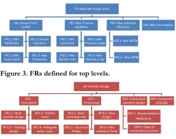
In this sense, the proposal is that AD must be used as a support methodology for the conceptual stage, which is more focussed on human creativity and intuition, aiming to guide the initial decisions in a more rational approach. Then, if some axiom 1 violations subsist, they will be object of the detailed stage, through MDO application, since it is considered an appropriate methodology to explore the interacting phenomena. According to this proposal, firstly, AD was undertaken in order to support the conceptual design. In this stage, the initial mould’s design decisions were defined according to the FRs-DPs mapping developed for the upper levels (Figure 3 and Figure 4).
FR -Replicate plastic parts
FR1-Assure Part's quality FR1.1 -Min Deflection FR1.2 -Assure Tolerance FR1.3 -Min visual marks FR1.4 -Max Properties FR2 -Max Process capability FR2.1- Min Cycle time FR2.2 -Min Pressure range FR2.3 -Min Mould´s size FR2.4 -Min Volume scrap FR3 -Max solutions efficiency FR3.1 -Min MTTR FR3.2 - Max MTBF FR4 -Max information
Figure 3. FRs defined for top levels. DP -Mould's Design DP1 -Conceptual DP1.1 -Heat-transfer design DP1.2 - Partion plane DP 1.3 - Feeding design DP1.4 - Adequate temp. cycle DP2 -Processual DP2.1 -Heat-exchange rate DP 2.2 -Flow lenght DP2.2 - Structure design DP2.4 -Min volume of feed DP3 -Construtive solutions design DP3.1 -Standardization/ Modularity DP3.2 -Type of construtive solutions DP4 -Complexity of design
Figure 4. DPs defined for top levels.
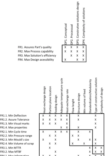
For the previous levels of decomposition, the respective design matrixes were developed using X and 0 to express the relation between FR to their associated DPs, where X indicates a mapping relationship and 0 lack of mapping relationship (Figure 5).
D P 1 . C o n ce p tu a l D P 2 . P ro ce ss u a l D P 3 . C o n st ru ti ve s o lu ti o n s d e si g n D P 4 . C o m p le xi ty o f so lu ti o n s
FR1. Assures Part's quality X X X X
FR2. Max Process capability X X X X
FR3. Max Solution's efficiency X X X
FR4. Max Design acessibility X X X
H e a t-e xc h a n g e d e si g n P a rt io n p la n e l o ca ti o n F e e d in g d e si g n A d e q u a te t e m p e ra tu re c y cl e H e a t-e xc h a n g e r a te F lo w l e n g h t S tr u ct u re d e si g n M in v o lu m e o f fe e d S ta n d a rd iz a ti o n /M o d u la ri ty T y p e o f co n st ru ct iv e s o lu ti o n C o m p le xi ty o f d e si g n FR1.1. Min Deflection X X X X X X X FR1.2. Assure Tolerance X X X X X X X
FR1.3. Min Visual marks X X X X X
FR1.4. Max properties X X X X
FR2.1. Min Cycle time X X X X X X
FR2.2. Min Pressure range X X X X
FR2.3. Min Mould’s size X X X X X
FR2.4. Min Volume of scrap X X X X X
FR3.1. Min MTTR X X X X
FR3.2. Max MTBF X X X X
FR4.1. Max Information X X X X X X X
Figure 5. Design matrix for upper levels of an injection mould design
Based on previous figures, it is possible to verify, as it was expected, that injection mould’s is a highly coupled design. Even though, as it was mentioned before, at this stage no special concerns will be taken regarding the coupled relations.
3 MDO FRAMEWORK
MDO is considering a powerful approach that exploits the synergism of the interdisciplinary couplings through a systematic and mathematically-based manner [AIAA, 1991]. Its goal is to find the optimal design of complex systems, achievable by systematic exploration of the alternatives generated at conceptual stage, which are then lead to the optimal state in the detailed stage. In order to pursue this goal, MDO adopts formal optimization methods to achieve design improvements, where some algorithms facilitate the exploration of large design spaces, including those that may be characterized by discrete variables or discontinuous functions [Korte, Weston et al., 1997]. This procedure enables product designers to deal with complex interactions, due to the existence of several constraints (e.g. technological, time, resources, etc), using quantitative mathematical models.
One major approach exploited in MDO is decomposing a large system into smaller subsystems, connected by information flows from outputs of one subsystem to the inputs of another. These information flows between subsystems analyses are termed couplings [English and Bloebaum, 2008]. Regarding the injection mould design, five subsystems were identified: Conceptual, Feeding, Structural, Heat-Exchange and Ejection. Conceptual subsystem includes the preliminary design decisions, such as type of mould (Structure design), the types of feeding system (Feeding design) etc, which were previously identified in the conceptual stage through FR-DP mapping. Feeding subsystem, which encompasses the Sprue, the Runners and the Gates as components, has the main function to assure melt distribution from the injection nozzle of the moulding machine into mould’s cavities. Structural subsystem is responsible for moulds coupling into the injection machine and for the overall assembly of its components. This subsystem must also guarantee the alignment and guiding of the mould. Heat-transfer subsystem is composed by a system of cooling channels, through which a coolant is pumped, aiming to transfer heat between mould, melt, coolant and environment. Depending on material, most of the times the objective is to remove heat from the mould, so that – once filled - the part is sufficiently rigid to be ejected. Ejection subsystem has the main function to knock out the injection moulded parts, in order to release them from the mould.
A block diagram (Appendix 2) was built in order to identify the feedforward and feedback paths between the different subsystems. It is important to note that the mapping is generic and was established independently of specific plastic part and injection machine characteristics (i.e. these modules and their relations are present in every mould design problem).
This approach facilitates the mathematical formulation of the mould design as a multidisciplinary system design problem. The multidisciplinary processes considered were rheological, which seeks to model and evaluate the mould
filling process, thermal, encompassing the heat transfer
between melt, mould and coolant, mechanical, concerning
the mould’s physical movements of opening and closure and
plastic part’s push-out, and, finally, structural aiming to
minimize the mould’s deformation induced by compressive and bending stresses, as well as, increase mould’s life cycle by load cyclic reduction. Some assumptions have been made to simplify the MDO approach to injection mould design. For example, the design of more complex elements of moulds (e.g. sliders) was not taken into account.
4 CYCLE TIME OPTIMIZATION
In order to validate the proposed framework, based on AD and MDO interlink, the cycle time is used as an example of one FRs, which should be minimize in order to increase process capability (CAs).
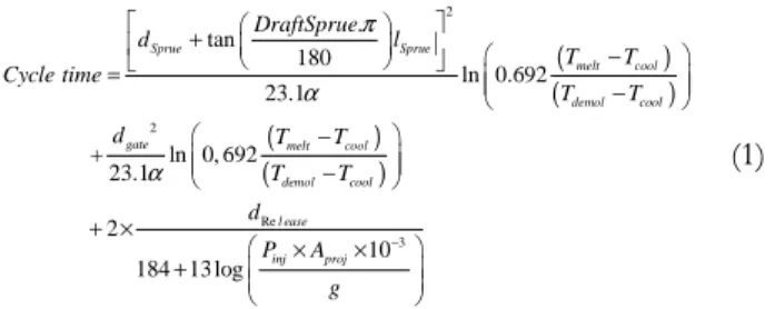
Theoretically, cycle time can be defined as the summation of the time for the different stages of injection moulding process. Therefore, cycle time can be mathematically express by Eq.1 (for more details see [Ferreira, Weck et al., 2008]).
( ) ( ) ( ) ( ) 2 2 Re . tan 180 ln 0.692 23.1 + ln 0, 692 23.1 2 184 13 log π α α + − = − − − + × + Sprue Sprue melt cool demol cool
gate melt cool
demol cool l ease in DraftSprue d l T T Cycle time T T d T T T T d P 10−3 × × j Aproj g (1)
Assuming that geometry and material of plastic part, as well as, injection machine parameters, are imposed by mould’s customer (which is usual in mould’s design process), the design variables that must be optimized in order to find the best solution, are:
dSprue = Sprue diameter [m]
lRunner = Runner length [m]
lGate = Gate length [m]
dGate = Gate diameter [m]
DraftSprue = Sprue draft angle [º]
lSprue = Sprue length [m]
Pinj = Injection Pressure [Pa]
dRunner = Runner diameter [m]
dRelease = Distance of part’s release [m]
Since Tmelt (i.e Melt temperature), Tmold (i.e Mould’s
temperature), Tdemold (Demoulded temperature) and α
(Coefficient of diffusitivity of material) are dependents of
material, and Aproj (Projected area of moulding) is function of
partition plane location, which was decided at the conceptual stage, these items are considered as parameters (invariable values). Nevertheless, it is important to note that mould’s design is assumed as an integrated optimization problem (according MDO approach). Therefore, for solving the cycle time minimization problem, due to existence of coupling relations between mould’s subsystems, there are several constraints and design variables, that must be also included in the optimization problem. For instance, the minimal distance
for cavity insert on X coordinate (Xins_cav) is function of Pinj,
since mould’s cavity insert must be strong enough to withstand millions of cyclic internal loads from injection pressures. In this sense, this variable must be dimensioned in
order to overcome this effort. At the same time, Xins_cav is
important to define cavity plates dimension, since cavity plate must accommodate cavity’s insert, as well as, the coolant lines of the heat-exchange subsystem. Therefore, as this example illustrates, the final optimal solution must be found taking in consideration the coupling relations and global constraints. In this context, the complete set of design variables, which will be object of cycle time optimization problem, is summarized in the next table.
Table 4. Design variables for cycle time optimization problem.
Design Variables (DVs) Symbol
Injection Pressure Pinj
Distance X cavity Insert Xins_cav
Distance Y cavity Insert Yins_cav
Final distance X cavity and core Xcav_core
Final distance Y cavity and core Ycav_core
Height of core insert Hcore_Ins
Height of cavity insert Hcav_ins
Final distance Z for cavity Zcav
Final distance Z for core Zcore
Release distance dRelease
Final distance Z for plate 1,9 Zplate_1,9
Final distance Z for plate 4 Zplate_4
Final distance Y for plate 5,6 Yplate_5,6
Final distance Z for plate 5,6 Zplate_5,6
Final distance Y for plate 7,8 Yplate_7,8
Final distance Z for plate 7 Zplate_7
Final distance Z for plate 8 Zplate_8
Length of sprue lSprue
Diameter of sprue dSprue
Draft angle of sprue DraftSprue
Diameter of runner dRunner
Length of runner lRunner
Diameter of gates dGates
Length gate lGate
Diameter channel of coolant dcool
Distance z from cavity surface to the
center of cooling line Zcool
Distance between turns in y pitch_cool
Number of changes in position of
coolant channel nturns
Length of coolant line lLine
Increase of temperature of coolant ∆Tcool
It is important to note that the space of design solutions is defined by all admissible values that each design variable can assumed. In this sense, a specific design solution will be characterized by a set of DPs, where each DP’s value is equal to the optimal value determined for the respective design variable. Afterwards, applying the Generalized Reduced Gradient 2 (GRG2), it was possible to determine the optimal solution, which represents a cycle time reduction of 7% for the initial solution (Table 5).
Table 5. Optimal vs Initial solution
DVs Units Initial Optimal=DPs
Pinj Pa 1,8E+08 1,55E+08
Xins_cav m 0,258 0,27 Yins_cav m 0,258 0,27 Xcav_core m 0,296 0,296 Ycav_core m 0,296 0,296 Hcore_Ins m 0,043 0,0428 Hcav_ins m 0,044 0,0443 Zcav m 0,056 0,046 Zcore m 0,056 0,046 dRelease m 0,075 0,075 Zplate_1,9 m 0,046 0,022 Zplate_4 m 0,046 0,046 Yplate_5,6 m 0,046 0,066 Zplate_5,6 m 0,046 0,106 Yplate_7,8 m 0,202 0,252 Zplate_7 m 0,016 0,026 Zplate_8 m 0,026 0,026 lSprue m 0,068 0,068 dSprue m 0,013 0,0124 DraftSprue º 1,000 1 dRunner m 0,009 0,0088 lRunner m 0,120 0,083 dGates m 0,001 0,0019 lGate m 0,001 0,001 dcool m 0,01 0,0048 Zcool m 0,025 0,010 pitch_cool m 0,05 0,019 nturns 7 7 lLine m 1,196 1,04 ∆Tcool ºC 0,5 1 Cycle time s 121,47 112,43
The GRG2 was adopted because it is widely used, since it is considered to be an effective method for large-scale nonlinear programming problem, with mostly smooth non-convex nonlinear functions. It is better adapted to handle problems with infeasible initial designs and in the presence of equality constraints. Some advantages of this method are that the extension for determining the solution of large sparse problems is conceptually simple, as well as, its availability and user-friendly nature.
Based on the previous values, it is possible to characterize the design solution that minimizes cycle time. Considering that CS increases linearly with cycle time (the additional improvement on CS made by cycle time coupling with other FRs is, at this stage, neglected), it is possible to conclude that this solution, when compared with baseline solution that were determined following practical guidelines [Centimfe, 2003], will lead to a 0.56% increase in CS (see Eq.2).
0.19 0.422 =0.08 =0.56% ∆ = × × ∆ ∆ CS cycle time cycle time (2)
5 CONCLUSION
The main objective of this paper was to describe a new approach, which links Axiomatic Design (AD) and Multidisciplinary Design Optimization (MDO), developed to support product design process. This framework aims to help designers to achieve a faster and a more efficient design of complex products, as a way to face the current market challenges. In this sense, the framework proposes to carry out the conceptual design through AD approach, aiming to map FRs with the corresponding DPs. Then, to support the detailed design stage, MDO is adopted with the objective to determine the best solution design through the exploitation of design space established by the options made at the conceptual stage.
In this sense, the starting point of our approach involves CAs identification and its translation into FRs. This task was performed by conducting semi-structure interviews. The data gathered was validated by an ECSI survey. Then, the identified FRs were mapped into DPs regarding only the upper levels of design (conceptual level). At this stage, even seeking for the independence of FRs, some remaining coupled relations can subsist and they are not considered prohibitive.
In relation to detailed design, a framework based on MDO was developed, which tackled mould design in a global way, through structural, thermal, rheological and mechanical domain integration. This framework was validated, using the GRG2 algorithm, where a baseline solution was optimized regarding cycle time, allowing a 7% reduction of cycle time. This result points out the potential for mould design improvements, since the developed framework can be used for search the best solution for mould design, amongst the design space establish after initial decisions made at the conceptual stage.
It is also important to note that, this framework encompasses the modules and the relations that are present in every mould design problem, which means that it can be used for any mould design. Of course, the design of more complex elements that can be present in moulds aren’t yet included in this framework. Nevertheless, the design of these elements will be object of future research. Finally, in order to develop a more realistic model for mould’s design and to get more accurate results, some high-fidelity models, like Moldflow, will also be integrate in the model.
6 REFERENCES
AIAA (1991). "White paper on current state of art", Technical Committee on Multidisciplinary Design Optimization (MDO) Centimfe (2003). Manual do projectista para moldes de injecção de
plásticos, Centimfe.
Chao, L. P. and K. Ishii (2004). "Design process error-profing project quality function deployment". ASME Design
Crawley, E., O. d. Weck, et al. (2004). "The influence of architecture in engineering systems", MIT - Engineering System Divison: 29.
English, K. and C. Bloebaum (2008). "Visual dependency stricture matrix for Multidisciplinary Design Optimization tradeoff studies." Journal of aerospace computing, information and
communication 5: 274-297.
Ferreira, I., J. A. Cabral, et al. (2008). "Customer´s satisfaction evaluation of Portuguese mould makers based on the ECSI approach". RPD 2008 - Rapid Product Development, Oliveira de
Azeméis - Portugal
Ferreira, I., J. S. Cabral, et al. (2006). "Axiomatic Design applied to injection moulds for plastic parts". RPD 2006 –
Rapid Product Development, Portugal.
Ferreira, I., J. S. Cabral, et al. (2007). "A new conceptual framework based on the ECSI model to support Axiomatic Design". Virtual and Rapid Manufacturing, Taylor&Francis. Ferreira, I., O. d. Weck, et al. (2008). "Multidisciplinary Optimization of Injection Molding Systems." Structural and
multidisciplinary optimization (Submitted).
Jang, B.-S., Y.-S. Yang, et al. (2002). "Axiomatic design approach for marine design problems." Marine Structures 15: 35-56.
Korte, J. J., R. P. Weston, et al. (1997). "Multidisciplinary Optimization Methods for Preliminary Design". Future
Aerospace in the Service of the Alliance.
Lu, M. H., C. N. Madu, et al. (1994). "Integrating QFD, AHP and benchmarking in strategic marketing." Journal of
Business&Industrial Marketing 9(1): 41-50.
Raharjo, H., M. Xie, et al. (2007). "A methodology to improve Higher Education quality using the Quality Function Deployment and Analytic Hierachy Process." Total Quality
Management 18(10): 1097-1115.
Rose, C. M., K. A. Beiter, et al. (1999). "Determining end-of-life strategies as a part of product definition". IEEE
International Symposium on Electronics and the environment Massachussets, IEEE.
Saaty, T. L. (1994). "How to make a decision: the Analytic Hierarchy Process." Interfaces 24: 19-43.
Suh, N. P. (1990). The principles of design, Oxford University Press.
Yang, K. and B. El-Haik (2003). Design for Six Sigma: A roadmap
ICAD-2009-XX
DP1 DP2 DP3 DP4 DP5 DP6 DP7 DP8 DP11 DP12 DP21DP22DP23 DP31 DP32 DP41 DP42 DP43 DP44 DP61DP62DP71DP72DP73DP74 DP75DP81 DP82 DP121 DP122 DP123 FR1 X FR2 X X FR3 X X X FR4 X X FR5 X X X X X FR6 X FR7 X X FR8 X FR11 X FR12 X FR21 X X X FR22 X FR23 X X FR31 X X FR32 X X FR41 X FR42 X FR43 X X X FR44 X FR61 X X FR62 X X FR71 X FR72 X X X X FR73 X X X X FR74 X X X X X FR75 X X X X X FR81 X FR82 X FR121 X X FR122 X X FR123 X FR221 FR222 FR321 FR322 FR431 FR432 FR441 FR442
APPENDIX 2 Conceptual Feed System (r=1,..,nRamif g=1,…,nGates ) Structural (i=1,...nplates) Ejection (p=1,…,npins ) Heat-Exchange System (c=1,…,nCool t=1,…,nturns ) Pinj (6.2) Heat-exchange rate(1.6) Partline (1.1) typeRunner (1.3) Positionmolding (1.2) InsY (2.2) Yi (2.5) Xi (2.4) Zi (2.6) InsZ (2.3) dRelease (2.7) dRunnerr(3.5) lGateg (3.9) dSprue (3.2) lRunnerr(3.4) nGate (3.8) Xg (3.11) Zcoolc(5.6) dCoolc (4.5) nCool (5.2) Ytc (5.5) Xtc (5.4) nPins (4.1) dPinsp (4.4) Xp (4.2) lPinsp (4.5) nturns (5.8) Pitchcool (5.7) TCool (5.1) typeMould (1.5) InsX (2.1) Yp (4.3) DraftSprue (3.3) nRamif (3.6) ndowns (3.7) Yg (3.12) Zg (3.13) dGateg (3.10) Coolant (1.6) lSprue (3.1) Tmold (1.7) tinj (6.1) PPack (6.4) tpack (6.3) Mechanisms(1.8)