F
ACULDADE DEE
NGENHARIA DAU
NIVERSIDADE DOP
ORTOCork to Enhance Damage Tolerance in
Composite Systems
João Pedro Correia Camacho
Integrated Masters in Mechanical Engineering
Supervisor: Prof. Dr. António Torres Marques Second Supervisor: Dr. Paulo Nóvoa
Cork to Enhance Damage Tolerance in Composite
Systems
João Pedro Correia Camacho
Integrated Masters in Mechanical Engineering
Abstract
Composite materials are nowadays extensively used, and their development is being studied to keep constantly improving the knowledge and optimizing their capabilities. One of the main concerns with their use is the impact behavior and in particular, their damage tolerance. Since it has been proven that adding a tough material as interlayer can be a solution to tackle this problem, this study aimed to understand how can cork improve the damage tolerance in composite systems. Due to cork’s properties, the fact that it is a natural material, and its importance to the portuguese economy, it comes as an interesting material to be studied to enhance the damage tolerance in composite systems.
This experimental work consisted in producing ten different laminates, with the exact same carbon-fibre prepreg and the same stacking sequence, only changing the interlayer material. As interlayer material, it was chosen to use cork films, Kraton™ and expanded cork granules with different thicknesses or concentrations and a reference laminate without any interlayer material. These laminates were cut into different specimens and subjected to tensile, impact and tensile after impact tests to characterize the material, understand their impact behaviour and assess their residual properties after being impacted with low energy levels.
The results obtained were not as concrete as it was expected, so it was not possible to take a conclusion of which cork format better enhances the damage tolerance, and which conditions are they best suited to be applied to do it (thickness or concentration). According with the results, adding cork films as interlayer material, highly improves the impact behaviour of the laminate, but on the other hand, their mechanical properties become highly compromised. In some particular situations, the thinner cork film used also managed to show some good results against the reference laminate in the tensile after impact test. Regarding expanded cork granules, their results in almost all the tests were not exactly consistent, but for some specific situations of concentrations and/or tests, they managed to show better results than the reference material. It is believed that this discrepancy of results is due to the spreading technique used to apply the expanded cork granules, that didn’t created an homogeneous layer, but resulted in some highly concetrated areas of the laminate and others with lower concentrarion.
Keywords: Laminates, Composite Systems, Cork, Mechanical Properties, Impact Behaviour; Carbon-Fibre; Damage Tolerance
Resumo
Os materiais compósitos são actualmente extensivamente usados e o seu desenvolvimento está constantemente a ser estudado para que o conhecimento sobre os mesmos possa ser melhorado e assim, optimizar as suas capacidades. Uma das maiores preocupações associadas ao uso de com-pósitos é o comportamento quando são submetidos a impactos, e em particular, a sua tolerância ao dano. Uma vez que foi provado que a adição de materiais tenazes ao laminado como interlayer poderá ser uma solução para combater este problema, este estudo visa compreender como é que a cortiça pode melhorar a tolerância ao dano em sistemas compósitos. A cortiça, devido às suas propriedades, o facto de ser um material natural e importante para a economia portuguesa, torna-se um material interessante para ser estudado como agente de melhoramento da tolerância ao dano em sistemas compósitos.
Este trabalho experimental consistiu em produzir dez laminados diferentes, com exatamente o mesmo pré-impregnado de fibra de carbono e a mesma sequência de empilhamento, mudando ape-nas o material de interlayer. Estes laminados foram cortados em diferentes provetes e submetidos a testes de tração, impacto e tração após impacto com o objectivo de caracterizar o material, com-preender o seu comportamento ao impacto e avaliar quais as suas propriedades residuais depois de terem sido impactados com baixos níveis de energia.
Os resultados obtidos não foram tão concretos como era esperado, então não foi possível tirar uma conclusão de qual o melhor formato de cortiça para melhorar a tolerância ao dano, e quais as condições óptimas para a sua aplicação (espessura ou concentração). De acordo com os resulta-dos, a adição de filmes de cortiça como material intercamada, melhora bastante o comportamento ao impacto do laminado, mas por outro lado, as suas propriedades mecânicas ficam altamente comprometidas. Em alguns casos particulares, o filme mais fino de cortiça usado foi capaz de mostrar bons resultados em comparação com o laminado de referência nos ensaios de tração após impacto. Relativamente aos grânulos de cortiça expandida, os resultados em praticamente todos os ensaios não foram consistentes, mas em algumas situações específicas de concentração e/ou ensaios, foram capazes de mostrar melhores resultados que o material de referência. Acredita-se que esta discrepância de resultados seja devida à técnica de espalhamento usada para depositar os grânulos de cortiça expandida, que não permitiu a criação de uma camada homogénea, mas resul-tou em algumas áreas altamente concentradas do laminado e outras com menor concentração.
Palavras-chave: Laminados, Sistemas Compósitos, Cortiça, Propriedades Mecânicas, Comporta-mento ao Impacto; Fibra de Carbono; Tolerância ao Dano
Acknowledgements
The ending of this dissertation project is not just the ending of a 5 months work, but it is also the culmination of a five years experience in this faculty, and I would like to share my deepest thanks and acknowledgements for all these people and entities.
First, I would like to thank Professor Dr. António Torres Marques for being my supervisor in this dissertation, for all the attention and suggestions given, for all the corrections and all the orientation, and most of all, for letting me learn and develop in this field of expertise both in his university courses, and now during this project. I also want to have this opportunity to express my huge gratitude to Dr. Paulo Nóvoa for his astonishing availability, his understanding, and his care and attention for this project. Being the person that I worked more closely with, his help and expertise in experimental part really made this work more easily done and effective. I also have to acknowledge the work and supervision that both have done on the topic of this thesis before, that set the foundation for all these last months’ experience.
This dissertation would not be complete if Faculdade de Engenharia da Universidade do Porto and INEGI didn’t give me the conditions to study, learn and work, and thus I would also like to give a special thank you to the people that made this dissertation possible: engineers and technicians from the mechanical tests laboratory and from materials and structural composites workshop in INEGI, specially to Fabio Neto for his assistance in the laminates processing, and laboratory of technological tests in DEM-FEUP. Taking this opportunity to mention FEUP, I also want to give a word of appreciation for all the community, specially for my mechanical engineering colleagues. This dissertation was also possible due to the contribution of Prof. Dr. Pedro Camacho that kindly shared the prepreg that was used, to AISOL (Amorim Isolamentos, José Andrade) for providing the expanded cork granules and to ACC (Amorim Cork Composites, Lino Rocha) for offering the cork films.
Since my first year in this faculty I was a part of Board of European Students of Technology (BEST). Joining this organisation was without a doubt, the best decision that I’ve ever made. I have to thank all the people throughout Europe that I’ve met, worked with, that taught me and inspired me. In particular, to all the people from BEST Porto, members and alumni, that were always more than that: were always my friends, my family. I’m so thankful for all they’ve done for me. For all the experiences and all the development, for all the discussions and insightful conversations, for all the failures and all the celebrations. All this and so much more. All of them shaped me into the person that I am today.
To my family, despite the fact that they’re not physically near me, I feel like they’re always with me. They have given me all the conditions to reach the stage that I’m now today. A paragraph is not enough to express how grateful I am to my mother and my father. For all the understanding, all the sacrifices and all the support. I owe them all that I have accomplished.
João Camacho
“Long you live and high you fly And smiles you’ll give and tears you’ll cry And all you touch and all you see Is all your life will ever be.”
Pink Floyd
Contents
Abstract i
Resumo iii
Acknowledgements v
Symbols and Abbreviations xix
1 Introduction 1
1.1 Historical Development . . . 1
1.2 Applications . . . 2
1.3 Importance of Damage Tolerance in Composite Systems . . . 2
1.4 Cork to enhance Damage Tolerance in Composite Systems . . . 3
1.5 Goals . . . 3
1.6 Structure and Summary of the Chapters . . . 4
2 Literature Review 5 2.1 Composite Materials . . . 5 2.1.1 Constituinte Materials . . . 5 2.1.2 Classification . . . 9 2.1.3 Hybrid Composites . . . 13 2.1.4 Manufacturing Processes . . . 14 2.1.5 Applications . . . 16 2.2 Cork . . . 18 2.2.1 Structure . . . 19 2.2.2 Chemical Composition . . . 20 2.2.3 General Properties . . . 22 2.2.4 Mechanical Properties . . . 23 2.2.5 Processing . . . 25 2.2.6 Wetting . . . 25 2.2.7 Cork Agglomerates . . . 26 2.2.8 Applications . . . 27
2.2.9 Innovation and Cork Powder . . . 27
2.3 Low Velocity Impact . . . 28
2.4 Basic Types of Damage in Composite Systems . . . 28
2.4.1 Fibre Breakage . . . 28
2.4.2 Matrix Cracking . . . 29
2.4.3 Fibre/Matrix Debonds . . . 29
2.4.4 Delaminations . . . 30 ix
2.5 Damage after Impact and Damage Tolerance . . . 31
2.6 Mechanical Tests . . . 32
2.6.1 Tensile Test . . . 32
2.6.2 Drop-Weight Test . . . 32
2.7 State of Art . . . 33
2.7.1 Methods to Enhance Damage Tolerance . . . 34
3 Experimental Procedure 39 3.1 Laminates . . . 39
3.1.1 Prepreg . . . 39
3.2 Hot Plates Press Curing . . . 44
3.3 Specimens Preparation . . . 44
3.4 Mechanical Tests . . . 46
4 Tests Results, Analysis and Discussion 49 4.1 Tensile Tests . . . 49
4.1.1 Reference - REF1 and REF2 . . . 50
4.1.2 Thin Cork Film - C1 . . . 51
4.1.3 Thick Cork Film - C2 . . . 52
4.1.4 Kraton™ granules 30 g/m2- K30 . . . 53
4.1.5 Kraton™ granules 40 g/m2- K40 . . . 54
4.1.6 Kraton™ granules 60 g/m2- K60 . . . 55
4.1.7 Expanded cork granules 10 g/m2- B10 . . . 56
4.1.8 Expanded cork granules 20 g/m2- B20 . . . 57
4.1.9 Expanded cork granules 30 g/m2- B30 . . . 58
4.1.10 Expanded cork granules 40 g/m2- B40 . . . 59
4.1.11 Analysis of Results . . . 60
4.2 Low Velocity Impact Tests . . . 68
4.2.1 Reference - REF . . . 68
4.2.2 Thin Cork Film - C1 . . . 70
4.2.3 Thick Cork Film - C2 . . . 71
4.2.4 Kraton™ granules 30 g/m2- K30 . . . 73
4.2.5 Kraton™ granules 40 g/m2- K40 . . . 74
4.2.6 Kraton™ granules 60 g/m2- K60 . . . . 76
4.2.7 Expanded cork granules 10 g/m2- B10 . . . 77
4.2.8 Expanded cork granules 20 g/m2- B20 . . . 79
4.2.9 Expanded cork granules 30 g/m2- B30 . . . 80
4.2.10 Expanded cork granules 40 g/m2- B40 . . . 82
4.2.11 Analysis of Results . . . 83
4.3 Tensile After Impact Tests . . . 87
4.3.1 Reference - REF . . . 88
4.3.2 Thin Cork Film - C1 . . . 89
4.3.3 Thick Cork Film - C2 . . . 90
4.3.4 Kraton™ granules 30 g/m2- K30 . . . 91
4.3.5 Kraton™ granules 40 g/m2- K40 . . . 92
4.3.6 Kraton™ granules 60 g/m2- K60 . . . 93
4.3.7 Expanded cork granules 10 g/m2- B10 . . . 94
4.3.8 Expanded cork granules 20 g/m2- B20 . . . 95
CONTENTS xi
4.3.10 Expanded cork granules 40 g/m2- B40 . . . 97
4.3.11 Analysis of Results . . . 98
4.4 Identation Tests . . . 110
4.4.1 Results . . . 112
4.4.2 Expanded cork granules 20 g/m2- B20 . . . 119
4.4.3 Analysis of Results . . . 121
5 Conclusion and Future Work 129
List of Figures
1.1 Usage of composite systems in Boeing 777 [10] . . . 3
2.1 Stress-strain curves of typical reinforcing fibres[10] . . . 6
2.2 Performance map of fibres used in structural composites[10] . . . 6
2.3 Classification scheme for the various composite types [8] . . . 9
2.4 Multidirectional laminate and reference coordinate system[10] . . . 11
2.5 Stacking of successive oriented fibre–reinforced layers for a laminar composite[8] 11 2.6 Designation of composite laminates[8] . . . 12
2.7 Scheme of a cross section of a sandwich panel[8] . . . 13
2.8 Construction of a composite sandwich panel with a honeycomb core[8] . . . 13
2.9 Construction of a composite sandwich panel with a honeycomb core[8] . . . 15
2.10 Usage of composite materials in A380 a) Components with carbon fibre b) Mate-rials distribution (weight breakdown) on A380 structure[27] . . . 17
2.11 Harvesting of cork oak[14] . . . 18
2.12 Schematic representation of axial section of cork oak tree; (A) cork (suberose tissue), (B) subero-phellogenic change, (C) phellogenium, (D) liber tissue, (E) liberwood change, (F) wood, (G) bark, (H) lenticular channels, (I) area for stopper production, (J) annual growth rings[24] . . . 19
2.13 Representation of cellular disposition in cork. The arrows indicate the names of the three sections and corresponding directions[24] . . . 20
2.14 SEM micrograph of cork: a)radial section; b) tangential section [24] . . . 20
2.15 Structure of cork oak cell wall;(T) tertiary wall, (S) secondary wall, (W) waxes and suberin, (P) primary wall, (M) medium lamella, (Po) pore [24] . . . 21
2.16 Schematic representation of cork cells; a radial section: l, prism base edge; d, wall thickness; b tangential/ axial section (perpendicular to radial direction): h, prism height; detail of cellular structure walls of cork showing its main components [24] 21 2.17 Typical compressive stress–strain curve for cork . . . 23
2.18 Stress–strain curves in tensile tests for cork, in all directions: T, tangential; A, axial; R, radial [24] . . . 24
2.19 Contact angle between the surface and the liquid [12] . . . 25
2.20 Variation of contact angle with time of a cork-polyester system . . . 25
2.21 Matrix crack and delamination initiation [15] . . . 29
2.22 Fibre-matrix debonding [15] . . . 30
2.23 Basic delamination modes [10] . . . 30
2.24 Schematic evolution of permanent indentation versus impact energy level [22] . . 31
2.25 Type 1B specimen[7,6] . . . 32
2.26 Type 2 specimen[7,6] . . . 32
2.27 Type 3 specimen[7,6] . . . 32 xiii
2.28 Impact Device with Cylindrical Tube Impactor Guide Mechanism [1] . . . 33
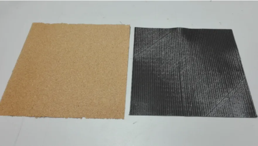
3.1 Thin cork film being applied on the laminate as interlayer . . . 41
3.2 Expanded cork granules being deposited as an interlayer material . . . 43
3.3 Expanded cork granules . . . 43
3.4 Drop-weight impact specimens . . . 45
3.5 TAI specimens . . . 46
3.6 Tensile test specimens . . . 46
3.7 ROSAND – Instrumented Falling Weight Impact Tester, Type 5 H.V. . . 47
4.1 Stress–Strain curve for REF Specimens . . . 50
4.2 Tensile test of C1 specimens . . . 51
4.3 Tensile test of C2 specimens . . . 52
4.4 Tensile test of K30 specimens . . . 53
4.5 Tensile test of K40 specimens . . . 54
4.6 Tensile test of K60 specimens . . . 55
4.7 Tensile test of B10 specimens . . . 56
4.8 Tensile test of B20 specimens . . . 57
4.9 Tensile test of B30 specimens . . . 58
4.10 Tensile test of B40 specimens . . . 59
4.11 Ultimate Tensile Strengths’ comparison between C1, C2 and REF . . . 60
4.12 Young’s modulus’ comparison between C1, C2 and REF . . . 61
4.13 Ultimate Tensile Strengths’ comparison between K30, K40, K60 and REF . . . . 62
4.14 Young’s modulus’ comparison between K30, K40, K60 and REF . . . 62
4.15 Ultimate Tensile Strengths’ comparison between B10, B20, B30, B40 and REF . 64 4.16 Young’s modulus’ comparison between B10, B20, B30, B40 and REF . . . 64
4.17 Ultimate Tensile Strengths’ comparison between all laminates . . . 66
4.18 Young’s modulus’ comparison between all laminates . . . 66
4.19 Impact’s Force vs Time curve REF specimens . . . 69
4.20 Impact’s Energy vs Time curve REF specimens . . . 69
4.21 Impact’s Force vs Time curve C1 specimens . . . 70
4.22 Impact’s Energy vs Time curve C1 specimens . . . 71
4.23 Impact’s Force vs Time curve C2 specimens . . . 72
4.24 Impact’s Energy vs Time curve C2 specimens . . . 72
4.25 Impact’s Force vs Time curve K30 specimens . . . 73
4.26 Impact’s Energy vs Time curve K30 specimens . . . 74
4.27 Impact’s Force vs Time curve K40 specimens . . . 75
4.28 Impact’s Energy vs Time curve K40 specimens . . . 75
4.29 Impact’s Force vs Time curve K60 specimens . . . 76
4.30 Impact’s Energy vs Time curve K60 specimens . . . 77
4.31 Impact’s Force vs Time curve B10 specimens . . . 78
4.32 Impact’s Energy vs Time curve B10 specimens . . . 78
4.33 Impact’s Force vs Time curve B20 specimens . . . 79
4.34 Impact’s Energy vs Time curve B20 specimens . . . 80
4.35 Impact’s Force vs Time curve B30 specimens . . . 81
4.36 Impact’s Energy vs Time curve B30 specimens . . . 81
4.37 Impact’s Force vs Time curve B40 specimens . . . 82
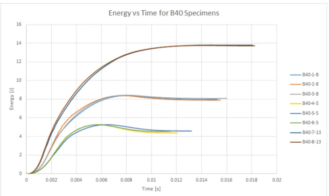
4.38 Impact’s Energy vs Time curve B40 specimens . . . 83
LIST OF FIGURES xv
4.40 Peak force vs impact energy of all laminates . . . 85
4.41 Final deflection vs impact energy of all laminates . . . 85
4.42 Absorbed energy vs impact energy of all laminates . . . 86
4.43 Energy recovery rate for each impact energy and all laminates . . . 87
4.44 Stress–Strain curve for TAI REF Specimens . . . 88
4.45 Stress–Strain curve for TAI C1 Specimens . . . 89
4.46 Stress–Strain curve for TAI C2 Specimens . . . 90
4.47 Stress–Strain curve for TAI K30 Specimens . . . 91
4.48 Stress–Strain curve for TAI K40 Specimens . . . 92
4.49 Stress–Strain curve for TAI K60 Specimens . . . 93
4.50 Stress–Strain curve for TAI B10 Specimens . . . 94
4.51 Stress–Strain curve for TAI B20 Specimens . . . 95
4.52 Stress–Strain curve for TAI B30 Specimens . . . 96
4.53 Stress–Strain curve for TAI B40 Specimens . . . 97
4.54 Ultimate Tensile Strength after impact comparison between C1, C2 and REF . . . 98
4.55 Young’s modulus after impact comparison between C1, C2 and REF . . . 99
4.56 Reduction of Ultimate Tensile Strength after impact comparison between C1, C2 and REF . . . 99
4.57 Reduction of Young’s modulus after impact comparison between C1, C2 and REF 100 4.58 Ultimate Tensile Strength after impact comparison between K30, K40, K60 and REF . . . 101
4.59 Young’s modulus after impact comparison between K30, K40, K60 and REF . . 101
4.60 Reduction of Ultimate Tensile Strength after impact comparison between K30, K40, K60 and REF . . . 102
4.61 Reduction of Young’s modulus after impact comparison between K30, K40, K60 and REF . . . 102
4.62 Ultimate Tensile Strength after impact comparison between B10, B20, B30, B40 and REF . . . 103
4.63 Young’s modulus after impact comparison between B10, B20, B30, B40 and REF 104 4.64 Reduction of Ultimate Tensile Strength after impact comparison between B10, B20, B30, B40 and REF . . . 104
4.65 Reduction of Young’s modulus after impact comparison between B10, B20, B30, B40 and REF . . . 105
4.66 Ultimate Tensile Strength after impact comparison between all laminates . . . 106
4.67 Young’s modulus after impact comparison between all laminates . . . 106
4.68 Reduction of Ultimate Tensile Strength after impact comparison between all lam-inates . . . 107
4.69 Reduction of Young’s modulus after impact comparison between B10, B20, B30, B40 and REF . . . 108
4.70 Indentation for C1, C2 and REF over time . . . 122
4.71 Indentation reduction for C1, C2 and REF over time . . . 122
4.72 Permanent indentation for C1, C2 and REF . . . 122
4.73 Indentation for K30, K40, K60 and REF over time . . . 123
4.74 Indentation reduction for K30, K40, K60 and REF over time . . . 123
4.75 Permanent indentation for K30, K40, K60 and REF . . . 124
4.76 Indentation for B10, B20, B30, B40 and REF over time . . . 124
4.77 Indentation reduction for B10, B20, B30, B40 and REF over time . . . 125
4.79 Indentation for 5 J impact energy . . . 125
4.80 Indentation for 8 J impact energy . . . 126
4.81 Indentation reduction for 5 J impact energy . . . 127
4.82 Indentation reduction for 8 J impact energy . . . 128
List of Tables
2.1 Differences in results of quantitative analysis of cork chemical composition [24] . 21 2.2 General Properties of Cork; R, measured in radial direction; NR, measured in
non-radial directions [24] . . . 22
2.3 General mechanical properties of cork; R, measured in radial direction; NR, mea-sured in non-radial directions [24] . . . 24
2.4 Properties of expanded cork agglomerate [24] . . . 27
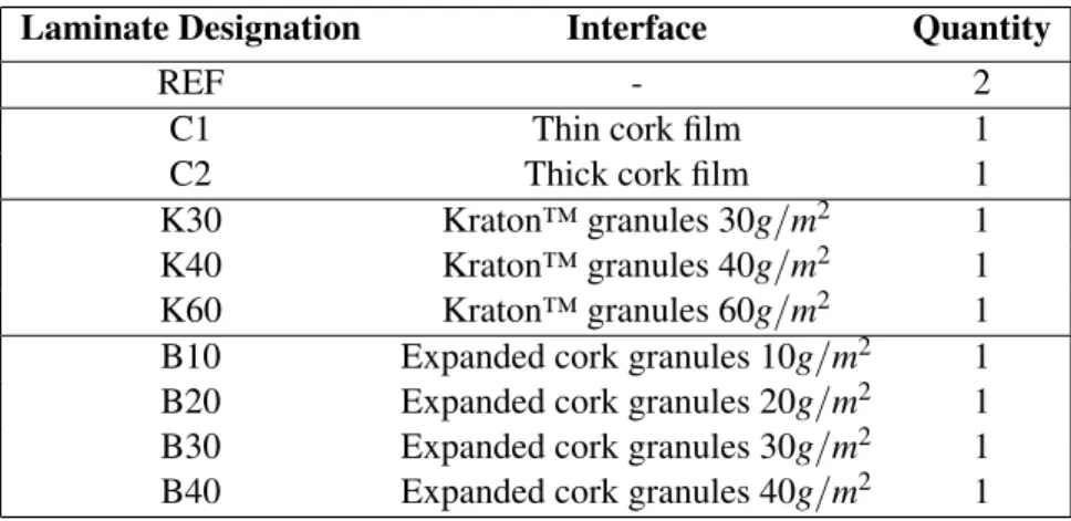
3.1 Designation and quantity used for each laminate . . . 40
3.2 Properties of 8245 cork film . . . 41
3.3 Properties of 8245 cork samples . . . 41
3.4 Properties of CORECORK NL20 . . . 42
3.5 Measures taken from CORECORK NL20 samples . . . 42
3.6 Properties of expanded cork . . . 43
3.7 Properties of expanded cork . . . 43
3.8 Properties of Kraton™ D-1102 . . . 44
3.9 Designation of the laminates with Kraton™ and their respective Kraton™ concen-tration . . . 44
3.10 Measures taken from the laminates after rectification. The thickness value is the average value of the thickness measurements of taken from each side . . . 45
3.11 Dimensions and quantity of the specimens for each test. . . 45
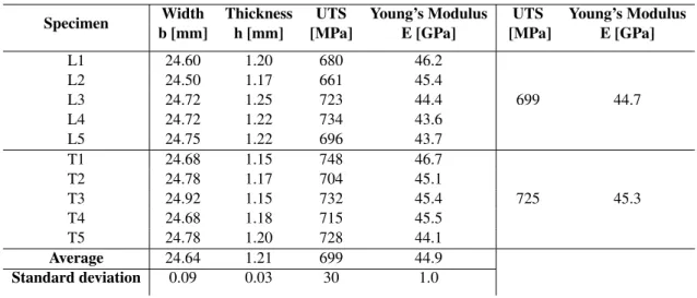
4.1 Dimensions and mechanical properties of REF tensile tests’ specimens . . . 50
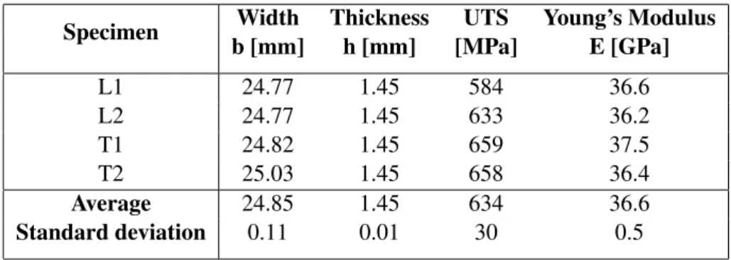
4.2 Dimensions and mechanical properties of C1 tensile tests’ specimens . . . 51
4.3 Dimensions and mechanical properties of C2 tensile tests’ specimens . . . 52
4.4 Dimensions and mechanical properties of K30 tensile tests’ specimens . . . 53
4.5 Dimensions and mechanical properties of K40 tensile tests’ specimens . . . 54
4.6 Dimensions and mechanical properties of K60 tensile tests’ specimens . . . 55
4.7 Dimensions and mechanical properties of B10 tensile tests’ specimens . . . 56
4.8 Dimensions and mechanical properties of B20 tensile tests’ specimens . . . 57
4.9 Dimensions and mechanical properties of B30 tensile tests’ specimens . . . 58
4.10 Dimensions and mechanical properties of B30 tensile tests’ specimens . . . 59
4.11 Mechanical properties of C1 and C2 and their reduction . . . 61
4.12 Mechanical properties of K30, K40 and K60 and their reduction . . . 62
4.13 Mechanical properties of B10, B20, B30, B40 and their reduction . . . 65
4.14 Mechanical properties of C1 and C2 and their reduction . . . 67
4.15 Values from REF Specimens’ impact test . . . 68
4.16 Values from C1 Specimens’ impact test . . . 70
4.17 Values from C1 Specimens’ impact test . . . 71 xvii
4.18 Values from K30 Specimens’ impact test . . . 73 4.19 Values from K40 Specimens’ impact test . . . 74 4.20 Values from K60 Specimens’ impact test . . . 76 4.21 Values from B10 Specimens’ impact test . . . 77 4.22 Values from B20 Specimens’ impact test . . . 79 4.23 Values from B30 Specimens’ impact test . . . 80 4.24 Values from B40 Specimens’ impact test . . . 82 4.25 Average values from all specimens’ impact test . . . 84 4.26 Specimens for each laminate and their respective impact energy . . . 88 4.27 Dimensions and mechanical properties of REF tensile tests’ specimens . . . 88 4.28 Dimensions and mechanical properties of C1 tensile tests’ specimens . . . 89 4.29 Dimensions and mechanical properties of C2 tensile tests’ specimens . . . 90 4.30 Dimensions and mechanical properties of K30 tensile tests’ specimens . . . 91 4.31 Dimensions and mechanical properties of K40 tensile tests’ specimens . . . 92 4.32 Dimensions and mechanical properties of K60 tensile tests’ specimens . . . 93 4.33 Dimensions and mechanical properties of B10 tensile tests’ specimens . . . 94 4.34 Dimensions and mechanical properties of B20 tensile tests’ specimens . . . 95 4.35 Dimensions and mechanical properties of B30 tensile tests’ specimens . . . 96 4.36 Dimensions and mechanical properties of B40 tensile tests’ specimens . . . 97 4.37 Mechanical properties of REF, C1 and C2 and their reduction after impact . . . . 100 4.38 Mechanical properties of REF, K30, K40 and K60 and their reduction after impact 103 4.39 Mechanical properties of REF, B10, B20, B30 and B40 and their reduction after
impact . . . 105 4.40 Reduction of the mechanical properties with an impact of 2.5 J . . . 108 4.41 Reduction of the mechanical properties with an impact of 3.5 J . . . 108 4.42 Reduction of the mechanical properties with an impact of 5.0 J . . . 108 4.43 Mechanical properties of the laminates and their reduction after impact . . . 110 4.44 Indentation results for REF specimens . . . 112 4.45 Indentation evolution for REF specimens . . . 112 4.46 Indentation results for C1 specimens . . . 113 4.47 Indentation evolution for C1 specimens . . . 113 4.48 Indentation results for C2 specimens . . . 114 4.49 Indentation evolution for C2 specimens . . . 114 4.50 Indentation results for K30 specimens . . . 115 4.51 Indentation evolution for K30 specimens . . . 115 4.52 Indentation results for K40 specimens . . . 116 4.53 Indentation evolution for K40 specimens . . . 116 4.54 Indentation results for K60 specimens . . . 117 4.55 Indentation evolution for K60 specimens . . . 117 4.56 Indentation results for B10 specimens . . . 118 4.57 Indentation evolution for B10 specimens . . . 118 4.58 Indentation results for B20 specimens . . . 119 4.59 Indentation evolution for B20 specimens . . . 119 4.60 Indentation results for B30 specimens . . . 120 4.61 Indentation evolution for B30 specimens . . . 120 4.62 Indentation results for B40 specimens . . . 121 4.63 Indentation evolution for B40 specimens . . . 121
Symbols and Abbreviations
ASTM American Society for Testing and Materials BVID Barely Visible Impact Damage
CAI Compression After Impact
DEM Departamento de Engenharia Mecânica
FEUP Faculdade de Engenharia da Universidade do Porto ISO International Organization for Standardization
INEGI Instituto de Ciência e Inovação em Engenharia Mecânica e Engenharia Indus-trial
LVI Low Velocity Impact PMI Polymethacrylimide RTM Resin Transfer Molding TAI Tensile After Impact
b Specimen width [m] h Specimen thickness [m σ Stress [Pa]
ε Strain [%]
E Young’s Modulus [Pa]
E* Reduction of Young’s Modulus after impact [%] Ea Absorbed Energy [J]
L0 Distance between the grips of the strain gauge [m]
∆L0 Distance increase [m]
F Applied Force [N] γ Superficial tension [Pa] θ Contact angle [rad]g
UTS Ultimate Tensile Strength [Pa]
UTS* Reduction of Ultimate Tensile Strength after impact [%]
Chapter 1
Introduction
Nowadays, technological knowledge is evolving at a high speed and thus, companies are starting to implement the new findings in their products. One of the biggest impacts that technology had and still has, is what we know about materials. It was natural for human kind to craft materials that can combine low density and good mechanical properties, without neglecting economical reasons. Composite materials can be defined as a material system made from two or more materials (carbon fibre and epoxy resin, for instance), ending up having a material with better properties than the single materials.
When these materials started to blossom, its usage was mainly in highly demanding appli-cations (aerospace & aeronautics, for instance), such that the final cost was not a criteria but, as technology and manufacturing processes started to evolve, the prices decreased and now, it’s possible to see composite systems in more common applications, starting to replace traditional engineering materials, such as steel or aluminium.
On the other hand, composites systems are still expensive (when compared with traditional materials), the manufacturing technology is still dependent, on some extent, on skilled hand la-bor with limited automation and standardization [10] and, due to their usual anisotropy and the different elements, are still very complex materials, specially on what damage is concerned.
1.1
Historical Development
Human kind, as a specie, is tightly related with the materials that was used. It first started with using stones (ceramics) to create tools and weapons with natural polymers and composites (wood). The following period, was marked by the usage of metals (gold, copper, bronze and iron), and in the last century steel and aluminum had a dominant role in the development of the human civilization.
On today’s world, polymers, ceramics and composites are again reclaiming their importance but, before men used the natural form of these materials, now men are engineering their own materials[10].
The concept of fibrous reinforcements dates back thousands years ago, but it was in the nine-teenth century that iron rods were used to reinforce masonry, the first step to what now is called steel-reinforced concrete.
The use of reinforced plastics in aircrafts and electrical components started in the forties and in 1942, the first fibreglass boat was made. The usage of advanced composites in aircraft components started in 1968 and in the late late 1970, the applications of composites expanded widely to other industries such as marine, automotive, sports and biomedical.
Composites technology suffered a rapid development in the last four decades, using the driving force of the aerospace industry that demanded weight saving and great performance. Today, there is also the need for quality assurance, reproducibility, and predictability of behaviour over the lifetime of the structure.
New advancements are still happening, such as new types of carbon fibres with higher strength and ultimate strain, thermoplastic matrices to be used under certain conditions, smart composites, the utilization of nanocomposites and multiscale hybrid composites with multifunctional charac-teristics. The development of composites is also taking place in the manufacturing processes, due to their influence in the final properties and quality assurance. Although the technology is still in development, it has now reached a stage of maturity[10].
1.2
Applications
As it was aforementioned, the usage of composites started mainly in the aerospace and aeronautics industry, not just because of the great performance with low weight, but also the possibility to design a large variety of materials with different property combinations.
Today, it is possible to find composites in a broad variety of industries such as sports and leisure (helmets, surf boards, etc.), automotive industry, military, marine and bioengineering. A great example of current usage of composites is the Boeing 777 that has this type of materials in its fairing, floor beams, wind trailing edge surfaces and the empennage (Fig.1.1).
1.3
Importance of Damage Tolerance in Composite Systems
The main advantages of composite systems were presented, nevertheless composite materials are usually fragile and anisotropic, making them sensible to stress intensity factors, such as low veloc-ity impact [11] created by accidental loads during production, service or maintenance, for instance. The damage suffered by a composite material is responsible for a change in the internal tension distribution, and thus reducing the load capacity of the material.
The low velocity impact is by far, the most dangerous damage that can occur, due to the extensive damaged areas with delaminations and/or matrix rupture. It can also happen that the phenomenon is not assessed when it is visually inspected. This reason states the importance of studying damage, and impact situations in particular. Impact resistance is characterized by the
1.4 Cork to enhance Damage Tolerance in Composite Systems 3
Figure 1.1: Usage of composite systems in Boeing 777 [10]
capacity of the material to not suffer permanent damage, and damage tolerance is the capacity of a damaged composite to maintain its original strength and stiffness.
1.4
Cork to enhance Damage Tolerance in Composite Systems
Since damage tolerance is such an important topic in composite systems, different solutions and materials have been studied to improve this problem, and one of them is cork, which is what this study is all about. Cork plays an important role in portuguese economy and in the environment. On today’s world, there is a conscience for the environmental problems and scarcity of resources. Cork is a material that can solve both of these problems, since it’s a natural material and it comes from the cork oak, by which the cork is removed from the tree every 10 years, on av-erage, without causing any big harm. Concerning the properties, cork presents itself with low density, high compressibility and flexibility, good chemical stability, good thermal and acoustical insulation and also an interesting energy absorption capacity, making it an interesting solution to improve damage tolerance in composite systems.
1.5
Goals
This dissertation aims to perform an experimental study that keeps the work that has been done so far about the usage of cork to enhance the damage tolerance in composite systems. In order to do it, it was decided to produce different laminates, keeping the same carbon-fibre prepreg and
keeping the same stacking sequence, variating only two interlayers of the laminate with different solutions, to later compare the results. It is intended to use as interlayer two different cork formats: cork films of different thicknesses and expanded cork granules with different concentrations. In order to assess if these additions to the laminate cause an improvement of the damage tolerance, it was also decided to use Kraton™ granules (also with different concentrations), a commercial available solution, and a reference material, without any added material as interlayer.
1.6
Structure and Summary of the Chapters
• Chapter1- This chapter presents the motivation to study this possible solution, by including a brief explanation of this dissertation’s theme and the context of this study. It also includes the exposition of the goals and purposes of this project.
• Chapter2- Chapter two includes the a literature review of the fundamental theoretical con-cepts that are important under the context of composite systems, low velocity impacts and damage tolerance. It also exposes the state of art in this field of expertise, by presenting what has been done so far under this topic. These chapter also looks to answer the decisions and choices that were made during the laminates’ design and production, and experimental tests.
• Chapter3- Here there is a description of the whole experimental and laboratorial procedure, mentioning how was the fabrication of the laminates (and specimens), and the mechanical tests that were performed.
• Chapter4 - Chapter four presents all the results obtained during the mechanical tests and analysis of the results.
• Chapter 5 - The fifth and last chapter aims to answer the questions proposed, through a conclusion, and presents some future work suggestions.
Chapter 2
Literature Review
2.1
Composite Materials
A composite material is a material that consist of two or more combined constituents which are combined at macroscopic level and are not soluble in each other. Its properties highly depend on the properties of its constituent phases. One of the phase is called reinforcement, which is harder and stronger, and the other phase is not so mechanically resistant, but also provides interesting properties to the whole material, called matrix. Both constituents are usually arranged to have one or more dispersed phases, reinforcements, in a continuous one, the matrix.
The properties of a composite are a function of its constituents, their relative amounts and the interaction between them. The geometry of the dispersed phase is one of the most relevant factors to take into account, such as the shape, size, distribution and orientation[8]. Besides all of this factors, they can usually be easily controlled and changed to get the desired properties.
Using composite materials, gives the engineers a lot of advantages, since it’s possible to craft their own material according with the applications, which it not so easily done with other tradi-tional materials such as steel, aluminium or polymers. These traditradi-tional materials, usually present uniform mechanical properties in all directions since they are isotropic and homogeneous, which doesn’t happen in composites because, most of the times, they are anisotropic or orthotropic.
2.1.1 Constituinte Materials
2.1.1.1 Reinforcement
As the name says, the reinforcement is the resistance phase of the composite material and thus, it has the highest relevance for the final product. Although it depends on the final application, it is de-sirable that the reinforcement has high stiffness, high strength and the lowest density possible[10]. A composite can be reinforced by particles or by fibres. The particle reinforcement provides a higher stiffness value to the matrix, but it doesn’t improve much the global mechanical resistance properties. The reinforcement usually comes in the shape of fibres, that can have different length and/or orientation, influencing the degrees of anisotropy. Due to the small section area, the fibres
cannot be used alone, so they usually are immersed in a polymeric matrix, which helps to transfer the load between the fibres and protect them from the outside environment.
Fibre reinforced materials, comparatively to metals, have better specific resistance and modu-lus, but the absolute properties have lower values.
The most used reinforcement materials are the glass fibre, boron, carbon and aramid (Kevlar®). Most of the fibrs have a linear behaviour as it is shown in Figure2.1and2.2.
An introduction on carbon fibre is going to be made, since it’s the material used during this study.
Figure 2.1: Stress-strain curves of typical reinforcing fibres[10]
2.1 Composite Materials 7
Carbon Fibre
As it was mentioned before, the most used fibres are glass fibre, boron, carbon and aramid (Kevlar®), but carbon is the most commonly used reinforcement in advanced (i.e., non fibreglass) polymer matrix composites and it comes with different properties depending on the manufacturing process[10].
Although the name of the reinforcement is carbon fibre, carbon is an element. The stable form of crystalline carbon at ambient conditions is graphite. Carbon fibres are not totally crystalline, but have both crystalline (graphitic) and noncrystalline regions, these last ones don’t have a three-dimensional arrangement of hexagonal carbon network, as it happens with graphite.
Fibres have a diameter that normally range between 4 and 10 µm, and usually they are coated with an epoxy protection that can also improve the adhesion the the polymer matrix. The man-ufacturing process that produces the fibres is relatively complex, but it has been developing and now it’s relatively inexpensive and cost effective[8].
Carbon fibres have the highest specific modulus and specific strength of all reinforcing fibre materials and they are able to retain their values at high temperatures, but they can suffer from high-temperature oxidation. At room temperature, this material is not affected by moisture or by a wide variety of solvents, acids and bases.
This type of fibre are now being extensively used in sports and recreational equipment, such as fishing rods, golf clubs, filament-wound rocket motor cases, pressure vessels and aircraft and helicopters structural components.
2.1.1.2 Matrix
Matrix is the other phase of a composite material, and the four types of matrices used are poly-meric, metallic, ceramic and carbon, but the more extensively used are the polymeric ones, that can be thermoplastics or thermoset. Polymeric matrices are also easier to manufacture due to the relatively low temperature to process.
The purpose of the matrix in the system is mainly to bind the fibres together, acting as a medium by which the external stresses are transmitted and distributed to the fibres and thus, only a small percentage of the load is applied on the matrix phase. Matrix also serves the purpose of protecting the fibres from surface damage, such as mechanical abrasion or chemical reactions with the environment, that can induce surface flaws and from there, form cracks, leading to a failure of the material at low stress interactions. Due to the matrix material’s softness and plasticity, the matrix prevents the propagation of brittle crack from fibre to fibre, that otherwise would induce a catastrophic failure. In order for this to happen, it is important that the adhesive bonding forces between fibre and matrix are high[8].
For the experimental work, it was used an epoxy resin, a polymer matrix. Some details about this type of matrix is presented in this document.
Polymer Matrix
can be thermoplastic or thermoset. The biggest difference between them is that thermoset do not melt upon reheating, and at high temperatures, it starts decomposing. Thermosets are the most predominant type of matrix system, and they undergo polymerization and cross-linking during curing with a hardening agent and heating. Thermoplastics are fully polymerized polymers and can be altered physically by softening or melting. Still regarding thermoplastics, they can be processed in less time and have a higher glass transition, but have a high temperature-dependent behaviour. They are also much less sensitive to moisture absorption and exhibit higher fracture toughness, but a short fatigue life.
The most common polymers used in composite matrices are unsaturated polyester, epoxies, polyimides, phenolic and vinylesters (thermsets) and polypropylene (PP), polyphenylene sulfide (PPS), polysulfone, poly-ether-ether-ketone (PEEK) (thermoplastics).
Thermoset resins offer some advantages over thermoplastic ones, such as better fibre wetting, which decreases the porosity level, and they also require lower temperature and pressure to man-ufacture, which may lead to a cheaper and energy saving process and they are easier to machine. On the other hand, thermoset resins require a longer curing time, and thus a smaller production rate and it was mentioned before, since they cannot be reheated it’s harder to recycle.
When choosing a resin to use as a matrix, the characteristics to take into consideration are: adhesion capacity to be able to use the full potential of the resin in terms of mechanical properties, although this characteristic also depends on the fibre and surface treatment, mechanical properties, stress crack resistance, fatigue resistance and degradation due to the contact with water or other substances.
The curing process of polymers begins with the growth and ramification of molecular chains, which increases the molecular weight of the material. During this process, the resin might contract due to the rearrangement and re-orientation of the resin molecules in the liquid and semi-liquid phase. As an example, polyester and vinyl ester can contract about 8%, but epoxy resin, which goes through a low molecular rearrangement and not a lot of volatile products, contracts about 2%. This low contraction results in better mechanical properties, since during the contraction, there are some internal tensions that can weaken the material[11].
Polymer curing happens through chemical reactions, with the help of some additives such as: amine, anhydride, carboxylic acids, phenols and alcohols. The velocity of the process can be easily controlled through the adquade selection of curing agents and catalysts.
Epoxy Resin
Epoxy resins are the most extensively used in advanced composites. Some of the advantages were already mentioned, when talked about thermoset resins. They consist on the absence of subproducts formed during the cure, low contraction while and after curing, resistance to solvents and other chemical products, and fatigue and creep resistance. They also have a good performance both at ambient and high temperatures: usually epoxy resins can be used until 80-120ºC, some of them can even be used at 240ºC. Due to the existence of ether and hydroxyl groups, they have even better impregnation capacity, when comparing with other thermoset resins. Although epoxy
2.1 Composite Materials 9
resin has numerous advantages, it is more expensive when compared to other polymers, that’s why it’s a material used more often in demanding applications. Besides, epoxy resin has also a brittle behaviour, but there are some methods that can improve it’s ductility, such as adding thermoplastic in the resin.
2.1.2 Classification
Composite systems can be classified into three main divisions: particle-reinforced composite, fibre-reinforced composite and structural composite (Fig. 2.3), subdividing into, at least, two subdivisions each[8].
Figure 2.3: Classification scheme for the various composite types [8]
2.1.2.1 Particle-Reinforced Composite
In this classification, particles are classified as a non-fibre material of small dimensions, and can be subdivided into large-particle and dispersion-strengthened composites. The distinction is made according with the reinforcement or strengthening mechanism. Dispersion-strengthened particles are normally much smaller, with diameters ranging between 10 and 100 nm. When using large particles reinforcement, the interaction particle-matrix cannot be treated on the atomic or molec-ular level, but it is rather used continuum mechanics. Since the reinforcement is a particle, the discontinuous phase is equiaxial, meaning that dimensions are approximately the same in all di-rections.
Globally, particle reinforcement can improve the stiffness of the polymeric matrix, but this re-inforcement does not have a considerable contribution for the improvement of the tensile strength, especially because high stiffness elements in a brittle matrix can lead to lot of stress concentration zones.
The improvement of mechanical behaviour depends on strong bonding at the matrix-particle interface. The interactions that lead to strengthening, occur on the atomic or molecular level -similar to that for precipitation hardening, as it happens with the metals, for instance, where the matrix bears the major portion of the load and the small dispersed particles hinder or impede the motion of dislocations.
2.1.2.2 Fibre-Reinforced Composite
Fibre-Reinforced composites are considered the most important composites[8]. This reinforce-ment is often used when the goal is to produce materials with high strength and/or stiffness on a weight basis.
They can be subdivided into continuous fibres or short fibres. In the case of short fibres, the ratio length/diameter is between 5 and 1000, with diameters of about 0.02 to 100 µm. These fibres are too short to produce a significant improvement in strength, mainly because the load transmis-sion effect by the matrix is more relevant, when compared with continuous fibre reinforcement. Regarding continuous fibres, they have a high length/diameter ratio, and the diameter can range from 3 to 200 µm, depending on the fibre type. The fibres used in this reinforcement type are stiffer and stronger, when compared with the bulk material. The load transfer happens according to its orientation and, in this situation, the purpose of the matrix becomes mainly to keep the fibres together.
These reinforcement types can be be formed by unidirectional or multidirectional layers. Us-ing unidirectional layers gives the composite high tensile modulus in the direction of the fibres, but regarding load in the perpendicular direction, it has a weak load capacity. When several layers are stacked, they are called laminate and when these layers are from different materials, it is called a hybrid laminate.
2.1.2.3 Structural Composites
The most common structural composites are the laminate composite and the sandwich panels. These structural composites are normally composed of both homogeneous and composite materi-als, and the properties of the final composite depend not only on the properties of the constituent materials but also on the geometrical design of the various elements.
Laminate Composites
Laminate composites are composed of two-dimensional sheets or panels stacked together that can have a prefered high-strength direction. These sheets or panels are called laminae (or plies, or layers), can have various thicknesses and consist of different materials. With all of these variables, the designers and engineers have a huge flexibility to craft their own material according with the final application, being possible to obtain the desired stiffness and thickness due to its anisotropy.
2.1 Composite Materials 11
The layers are stacked and cemented together and the orientation of the high-strength direction varies with each successive layer. Usually, the layers are bonded together by the same material of the matrix, making it unnecessary to add more materials[25][10].
Laminate composites have relatively high strength in a number of directions in the two-dimensional plane, however, the strength in any given direction is lower than it would be if all the fibres were oriented in that direction. The orientation of a ply is given by the angle between the reference x-axis and the major principal material axis (fibre orientation or wrap direction) of the ply measured in a counterclockwise direction on the x-y plane (Fig.2.4).
Figure 2.4: Multidirectional laminate and reference coordinate system[10]
The mechanical behaviour of a laminate is different from the behaviour of a single layer, but the behaviour of the whole laminate depends on the behaviour of each layer and the stacking sequence (Fig.2.5).
Figure 2.5: Stacking of successive oriented fibre–reinforced layers for a laminar composite[8] Laminate composites have a designation that indicates in a specific manner the number, type, orientation and stacking sequence of the plies. The configuration of the laminate indicating its ply composition is called the layup. The configuration indicating the exact location or sequence of the various plies, is called the stacking sequence. Some examples from Daniel Ishay[10] can be consulted in Figure2.6[10].
Figure 2.6: Designation of composite laminates[8]
Sandwich Composites
Sandwich composites are designed to provide solutions that are lightweight (usually come in the form of a beam or a panel) and have a relatively high stiffness and strength. They are composed of two outer sheets or faces, separated by a thicker core that is adhesively bonded to the sheets (Fig. 2.7).
The outer sheets, or faces are made of a relatively stiff and strong material, usually aluminum alloys, fibre-reinforced polymers, titanium, steel or plywood. These components are the responsi-bles to give to the structure a high stiffness and strength to the structure and must be thick enough to withstand tensile and compressive stresses from the loading.
Regarding the core, it is typically made of one of these threes material categories: rigid poly-meric foams (phenolic, epoxy or polyurethane), wood (balsa wood) and honeycombs (aluminium alloy or aramid polymer). The main functions of the core are to provide continuous support for the
2.1 Composite Materials 13
Figure 2.7: Scheme of a cross section of a sandwich panel[8]
faces, withstand transverse shear stresses and provide high shear stiffness to resist the buckling of the panel (so it should be thick enough).
As it was aforementioned, honeycomb cores are widely used in sandwich composites. They are structures-thin foils that have been formed into interlocking hexagonal cells, with axis orientation perpendicular to the faces planes (Fig.2.8). The strength and stiffness depend on the cell size, cell wall thickness and the material used as honeycomb.
Figure 2.8: Construction of a composite sandwich panel with a honeycomb core[8]
2.1.3 Hybrid Composites
This relatively new type of composite is obtained by using two or more different types of fibres in a single matrix and thus, it is possible to obtain better combination of properties than composites containing only a single fibre type. This system can be combined in a wide variety of ways which will affect the overall properties.
Composite laminates that contain plies of two or more different material types are also called hybrid composites, more specifically interply hybrid composites. An example of such combination might be a composite laminate that is made up of unidirectional glass/epoxy, carbon/epoxy and aramid/epoxy stacked together in a specific sequence[10].
The overall behaviour of hybrid composites comes from a weighted sum of the advantages and disadvantages of each component.
It is also possible to incorporate alternative materials such as industrial waste or even materials that come directly from nature such as natural fibres or natural resins and thus contribute to world sustainability.
2.1.4 Manufacturing Processes
The way a composite part is processed and manufactured, highly influences the final properties, and thus it’s one of the most important steps in the application of composite materials. The man-ufacturing process should be selected concurrently with material selection and structural design and, in the case of composite systems, it is governed by the matrix used[10].
Nowadays, there is still a barrier to the more extensive use of composite materials, and most of it is due to the high cost, which can be attributed to lack of cost-effective fabrication methods and the necessity for post process inspection to ensure quality of the material and part. With this being said, the final product must meet some general requirements, namely the fact that it must be free of defects (voids, cracks, fibre waviness), have uniform properties, be fully cured (having expected properties, for example: stiffness, strength, fatigue endurance) and reproducibility[10].
The finished product should also fulfil some specific goals of manufacturing, for example: control of reinforcement location/orientation, ply thickness, fibre volume ratio, voids, residual stresses and final dimensions. Regarding the process itself, the temperature must not exceed pre-set values, temperature distribution must be reasonably uniform throughout the part and an uniform cure must be accomplished in the shortest possible time.
There are a huge number of fabrication methods that are used today. Some examples of the ones more often used are: autoclave, vacuum bag and compression molding, filament winding, in-jection molding, pultrusion and resin transfer molding (RTM), but in this chapter, only the prepreg production process is going to be explained, since it’s the one used during the experiments. In all of these processes, there is a set of limitations, more specifically on the production rate, size, geometrical shape allowed, structural quality, homogeneity of the part, automatization and cost.
2.1.4.1 Prepreg Production Process
A prepreg is the composite industry term for continuous-fibre reinforcement pre impregnated with a polymer resin that is only partially cured, made to be ready for fabrication of composites. This material is delivered in the form of a tape that consists of layer of parallel or woven fibres that were already, as mentioned before, partially cured to be molded and fully cured by the industry without having to add any resin. There are prepregs with different reinforcements, but the more extensively used are the common fibres: carbon, glass and aramid, and both thermoplastic and thermoset resins are used. These prepreg tapes are made to meet certain specifications such as fibre volume ratio, ply thickness, and degree of partial cure (B-staging)[8].
2.1 Composite Materials 15
The prepreg manufacturing process for thermoset polymers is represented in figure2.9. It be-gins by collimating a series of spool-wound continuous-fibre tows, which are then pressed between sheets of release and carrier paper, by the mean of heated rollers in a process called calendering. The release paper sheets have already been coated with a thin film of heated resin of low viscosity to impregnate the fibres. A doctor blade guarantees a uniform thickness and width of the resin film by spreading the resin on the fibres. As the impregnated tape is spooled, the release paper sheet is removed[8].
Figure 2.9: Construction of a composite sandwich panel with a honeycomb core[8] The industry fabricates the composite firstly with the lay-up, laying the prepreg on a surface with the specific number of plies to provide the desired thickness (after the removal from the carrier backing paper). The stacking may be unidirectional, but more often, the fibre orientation is alternated to produce a cross-ply or angle-ply laminate. This lay-up can be made entirely by hand (hand lay-up), where the operators cut the length of the tape and position them in the desired orientation, but the lay-up can also be machine cut and then hand laid. The fabrication cost can be reduced by automation of the prepreg lay-up and by using other manufacturing procedures, eliminating the need for hand labor and thus, making it cost effective. After the lay-up, the prepreg goes through the application of heat and pressure simultaneously[8].
The prepreg is characterized by the resin content, which is usually about 32-45% by weight, tack (self-adhesive), drape ability (ability to conform to shapes), shelf life, out time and gel time[10].
Since the material is pre impregnated, it must be kept refrigerated at approximately -18ºC until the final use. Even when using it, the room temperature must be minimized since, for instance,
thermoset matrix undergoes curing reactions at room temperature. If the material is properly handled and stored, thermoset prepregs have a lifetime of at least six months or even longer.
2.1.5 Applications
Nowadays composite systems are used in a wide variety of industries for a wide variety of pur-poses. Some of the industries where composites are more extensively used are going to be men-tioned.
Aeronautical and Aerospace Industry
These industries were the booster for the study and investigation of this type of materials due to the constand demand for structures with low weight, great performance and that the final price, although has some importance, is not the main factor. It all started in the decade of 1970 in military aircrafts for secondary structural components, and latter on commercial aircrafts.
Nowadays, the usage of composite systems in aircrafts is well established in structural com-ponents. As an example, A380, from Airbus, has about 25% of its weight in composites (figure 2.10).
The main advantages, besides the decrease of weight, is the reduction of mechanical joints (allowing a decrease of manufacturing and assembly costs and, once again, a decrease of the structure’s weight) and fatigue and corrosion resistance.
Constructions and Infrastructures
It is a field of application where there is constant investigation, since the replacement of steel and concrete by composites allow a decrease of weight and an increase of corrosion resistance, resulting in an increase of structure’s life and a lower maintenance cost.
It is also possible to see composites being used in buildings isolation, doors, windows and floors, since it is possible to create composites that slow the fire progression.
Automobile Industry
The reduction of weight is one of the main motivating factors, making the automobile industry one of the main interested industries.
Fibreglass presents the bigger relevance in this industry, since carbon fibre is still quite expen-sive. The high production rate demanded by this industry, also limits the usage of epoxy resins due to the higher curing time.
In motor sports, the priority is high speed, being the final cost a secondary factor and, in this situations, carbon fibre and epoxy resins are more extensively used in the body, chassis, interior and suspension.
2.1 Composite Materials 17
Figure 2.10: Usage of composite materials in A380 a) Components with carbon fibre b) Materials distribution (weight breakdown) on A380 structure[27]
Sports Industry
Once again, low weight is one of the main motivation factors. Also corrosion resistance, good mechanical properties and ease of conformation make composite materials an interesting solution for the sports industry.
It is possible to see this type of materials in bikes, rackets, helmets and golf clubs, for instance. Naval Industry
Ship hulls, decks and interiors. These are the main parts where composites are used in this industry. About 90% of recreational crafts have fibreglass reinforced unsaturated polyester.
In competition boats, carbon fibre is prefered to be used due to lower weight and better me-chanical properties.
Biomedical Applications
Composites are also used in applications that include the diagnostic, treatment of diseases and its prevention. Some concrete examples are: implants, surgical and diagnostic devices, pacemakers, wheelchairs, mobility support equipments, packaging of certain drugs and instrumentation for chemical analysis.
Implants are one of the most challenging application, since it requires that the material has to be biocompatible, resistant to corrosion and fatigue and has to be able to maintain its properties over a long period of time. Usually materials such as carbon matrix and biocompatible polymeric matrices are used for these applications.
2.2
Cork
Cork is one of the most versatile natural raw materials known that has been used for many cen-turies. It is a very lightweight material, elastic, flexible and a good electrical, thermal, sound and vibration isolator [13]. Depending on the type, it is also impermeable to gases and liquids
It comes from the bark of the oak (Quercus suber L.) tree, which is periodically harvested (ev-ery 9-12 years, depending on the culture region) (Fig. 2.11). It flourishes only in specific regions of the western mediterranean (Portugal, Spain, Southern France, part of Italy, North Africa) and China. Europe has about 60% of total production area (cork forest) and produces more than 80% of the world’s cork, being Portugal the major cork producer with about three-quarters of all the cork[24].
Figure 2.11: Harvesting of cork oak[14]
Cork forests are of extreme importance to Europe’s southern semi-arid regions, since they prevent desertification and contribute to the perfect habitat for many animals and plants of the region. These forests are also extremely important with respect to the retention of carbon dioxide (CO2) and thus, contribute to the reduction of the greenhouse gas emissions and better climate. In
2.2 Cork 19
The cork oak produces three qualities of tissue. The first harvested is the virgin cork, which is irregular in structure, thickness and density, it is hard-rough and crumbly. After it is the reproduc-tion cork from the second striping, which is more regular than virgin cork. Following, it comes reproduction cork from subsequent stips, than can be used for cork stopper production, while all types of cork can be used for agglomerates (Fig.2.12).
Figure 2.12: Schematic representation of axial section of cork oak tree; (A) cork (suberose tis-sue), (B) subero-phellogenic change, (C) phellogenium, (D) liber tissue, (E) liberwood change, (F) wood, (G) bark, (H) lenticular channels, (I) area for stopper production, (J) annual growth rings[24]
Removing cork increases the water loss of the tree from the exposed surface and affects the tree growth (wood).
2.2.1 Structure
Cork is composed of an aggregate of cells, about 43 million per cubic centimeter. The cell’s dimensions can vary a lot even in the same plank.
Since the lateral cell walls (parallel to the radial direction) have a random orientation, the material can be considered transversely isotropic, meaning that all directions perpendicular to the radial direction (axial and tangential) are nearly equivalent (Fig. 2.13). Since there is a certain anisotropy in cork’s cellulars structure, the properties of cork will also be anisotropic.
Schematic representation of cellular disposition in cork growing section; arrows indicate names of the three sections and corresponding directions in cork planks.
The cells itself, can be described as a rectangular prisms, that are packed base-to-base in columns parallel to the radial direction of the tree. In this direction, the cells appear to have a 4- to 9-sided polygons (heptagonal, hexagonal and pentagonal) shape, and on the axial and tangential section, the structure resembles a brick wall[24].
Cork cells are close and hollow. Inside, they contain a gas, presumably similar to air [24]. This is the secret of this material, since the mixture of gases that fill each cell are responsible for
Figure 2.13: Representation of cellular disposition in cork. The arrows indicate the names of the three sections and corresponding directions[24]
cork’s lightness, compressibility, elasticity and the fact that cork can be compressed half of its size without losing any flexibility.
Figure 2.14: SEM micrograph of cork: a)radial section; b) tangential section [24]
2.2.2 Chemical Composition
The specific properties of cork highly depend on its chemical composition and, in turn, the chem-ical composition depends on factors such as the geographic origin, climate and soil conditions, genetics origin, tree dimensions, age and growth conditions [24].
As it happens in other tissues’ cells, cork’s cell walls can also be divided into two kinds of components: structural and non-structural. The structural components are mainly suberin (40%), lignin (22%) and polysaccharides (cellulose and hemicellulose) (18%), although the presence of polysaccharides are not considered relevant to cork’s cell wall properties. The non-structural com-ponents consist of the extractables (15%) (Table2.1).
2.2 Cork 21
Table 2.1: Differences in results of quantitative analysis of cork chemical composition [24]
Virgin Cork Reproduction Cork
Caldas Pereira Gil Caldas Pereira Parameswaran Holloway Carvalho Component (1986) (1981) (1998) (1986) (1981) (1981) (1972) (1968)
Suberin 45 45 42 48 33.5 33 37 50
Lignin 27 21 21.5 29 26 13 14.8 19
Polysaccharides 12 13 16 12 25 6 13
(celulose and hemicellulose)
Extractables 10 19 13 8.5 13 24 15.8 15
Ash 5 1.2 2.1 2.5 . . . 3
Others . . . 0.8 7 . . . 6 . . . .
More specifically, the cellular structure of cork wall consist of a thin lignin rich middle lamella, a thick secondary wall made from suberin and wax lamella and a thin tertiary wall of polysaccha-rides (Fig.2.15and2.16).
Figure 2.15: Structure of cork oak cell wall;(T) tertiary wall, (S) secondary wall, (W) waxes and suberin, (P) primary wall, (M) medium lamella, (Po) pore [24]
Figure 2.16: Schematic representation of cork cells; a radial section: l, prism base edge; d, wall thickness; b tangential/ axial section (perpendicular to radial direction): h, prism height; detail of cellular structure walls of cork showing its main components [24]
Suberin is the main component of cork’s cell wall. It is a biopolymer (polyester type) that confers low permeability to the cork, allowing cells to be hermetic and thus, able to retain all the gases that were inside the cells, explaining the low thermal and electrical conductivity of cork. Ligning is the component that gives hardness to cork’s cell walls.
2.2.3 General Properties
Cork has a set of unique properties that any other product, natural or artificial, until now, wasn’t able to match [11].
Cork’s specific mass can vary widely depending on it’s age and treatments to which it was subjected. Normal values are somewhere between 120-240 kg/m3. The low value of specific mass can once again be explained by the high gas content of the small cells.
The gas content and the cell size can also account for the very poor heat transfer properties of cork.
Another important characteristic of cork is the poor sound transmission. Owning to the low density and high porosity, most of the incident sound waves are absorbed and transformed into heat.
Some other special properties of cork are: good chemical stability, be impermeable to liquids and gases, good thermal insulator, fire resistant (does not release gases), low electrical conduc-tivity, excellent energy absorption capacity and high friction coefficient. Some values of these properties can be consulted on table2.2.
Table 2.2: General Properties of Cork; R, measured in radial direction; NR, measured in non-radial directions [24]
Property Value Ref.
Friction coefficient, boiled 0.2−1.2 (cork/glass and cork/steel) 111 0.97 (cork/cork, R) 111 0.77 (cork/cork, NR) 111 0.76 (cork/glass, R) 111 0.35 (cork/glass, NR) 111
Specific mass kgm−3 120−180 (amadia) 29
160−240 (virgin) 29
Surface energy, dispersive component, mJm−2 24−38 (40ºC) 32, 108
41 (25ºC) 171
Thermal conductivity, W m˘1K˘1 0.045 (cork) 1
0.025 (air) 1
0.2 (cork cell walls) 1 Electrical conductivity, Sm˘1 1.26 × 10⁻¹⁰(25◦C) 100
1.67 × 10⁻¹³(50◦C) 100 Acoustic resistivity, kgm˘2s˘1 1.2 × 10⁵ 177
Specific heat, Jkg˘1K˘1 350 1
Thermal diffusivity, m2s˘1 1 × 10⁻⁶ 1
Water diffusion coefficient, m2s˘1 4 × 10⁻¹⁰(NR) 1
![Figure 2.10: Usage of composite materials in A380 a) Components with carbon fibre b) Materials distribution (weight breakdown) on A380 structure[27]](https://thumb-eu.123doks.com/thumbv2/123dok_br/15486744.1040092/41.892.223.709.139.765/figure-composite-materials-components-materials-distribution-breakdown-structure.webp)
![Table 2.1: Differences in results of quantitative analysis of cork chemical composition [24]](https://thumb-eu.123doks.com/thumbv2/123dok_br/15486744.1040092/45.892.149.789.178.388/table-differences-results-quantitative-analysis-cork-chemical-composition.webp)
![Table 2.2: General Properties of Cork; R, measured in radial direction; NR, measured in non-radial directions [24]](https://thumb-eu.123doks.com/thumbv2/123dok_br/15486744.1040092/46.892.115.750.629.1133/table-general-properties-measured-radial-direction-measured-directions.webp)
![Table 2.3: General mechanical properties of cork; R, measured in radial direction; NR, measured in non-radial directions [24]](https://thumb-eu.123doks.com/thumbv2/123dok_br/15486744.1040092/48.892.121.757.533.1132/table-general-mechanical-properties-measured-direction-measured-directions.webp)
![Figure 2.24: Schematic evolution of permanent indentation versus impact energy level [22]](https://thumb-eu.123doks.com/thumbv2/123dok_br/15486744.1040092/55.892.195.748.217.689/figure-schematic-evolution-permanent-indentation-versus-impact-energy.webp)