F
ACULDADE DEE
NGENHARIA DAU
NIVERSIDADE DOP
ORTOControl and cooperation of marine
vehicles
Bruno Miguel Mateus Ferreira
Doctoral Program in Electrical and Computer Engineering Supervisor: Aníbal Castilho de Coimbra Matos Co-supervisor: António Paulo Gomes Mendes Moreira
Control and cooperation of marine vehicles
Bruno Miguel Mateus Ferreira
Doctoral Program in Electrical and Computer Engineering
Abstract
This thesis addresses the problem of controlling and coordinating autonomous marine vehicles. Distributed systems has become a standard solution for a large number of engineering problems. Marine robotics has also followed the same trend: coordinated surface and underwater vehicles have been used as a means to distribute possibly heterogeneous equipment over regions of inter-est. The work presented throughout this document has been motivated by recent challenges and constraints intrinsic to marine environments.
Firstly, a control application example is presented to stabilize a hovering autonomous under-water vehicle (AUV) in the vertical pose, that is, pitching up or down. This pose is specially appreciated for fast and efficient descent (or ascent) maneuvers. Moreover, a guidance law to drive the vehicle horizontally when it is in the vertical pose is proposed, envisioning potential positioning corrections when the vehicles is diving or surfacing.
Then, two methods to solve the problem of homing a vehicle to a given reference based on range-only measurements are provided, inspired from acoustic ranging applications. This rather simple task can be seen as a basic exercise of coordination between a vehicle and a, possibly moving, beacon. The first method is built from a combination of estimation and guidance while the second approach is based on the sensor, where only the range measurements are used to guide the vehicle towards its reference. These address the problem at kinematic level, presuming the existence of a lower level velocity control law which is subsequently formalized.
Local automatic control of vehicles and coordination are addressed here at different levels. Coordination of vehicle relies on the local control of each vehicle. The coordination scheme presented is composed of three main control layers. At the dynamics level, the vehicle velocity is stabilized around a desired reference vector, which is subsequently used in a guidance law. These then constitute the basic layers on which the coordination algorithm builds upon. For all these layers, special attention is given to practical problems that arise from model uncertainties and tracking errors. Following a bottom-up development, upper bounds on tracking errors are derived for both velocity and position in order to assess the achievable performances of the control method and also to ensure that the tracking task is satisfactorily fulfilled. As a by-product, a compilation of results is provided for error boundedness in velocity and position tracking.
Coordination of a team of autonomous marine vehicles is finally applied to tracking and esti-mation of a sound source located underwater based on time-of-arrival (TOA) measurements only. As the uncertainty of the estimate depends on the relative positions of the receivers, a solution that optimally places the receivers in space is proposed by taking advantage of the motion capabilities of a coordinated formation of vehicles.
Keywords: Marine vehicles, Underactuated vehicles, Homing, Vertical pose, Nonlinear con-trol, Formation keeping, Target localization, Coordination, Communication constraints
Resumo
A presente tese aborda o controlo e a coordenação de veículos marinhos autónomos. Os sistemas distribuídos têm-se tornado uma solução comum para um grande número de problemas de engen-haria. A robótica marinha tem seguido a mesma linha: veículos de superfície e submarinos têm sido utilizados como meios para distribuir equipamento, possivelmente heterogéneo, em regiões de interesse. O trabalho apresentado neste documento é motivado por desafios recentes e restrições intrínsecas ao meio marinho.
Primeiro, apresenta-se um exemplo de aplicação de método de controlo para a estabilização de um veículo submarino autónomo na pose vertical, isto é, inclinado para baixo ou para cima. Esta pose é particularmente interessante em cenários de descida (ou subida) rápida. Por outro lado, propõe-se uma lei de controlo para guiar o veículo horizontalmente, quando este se encontra na pose vertical, antecipando possíveis correções de posição aquando da submersão ou da emersão.
De seguida, inspirados em aplicações que usam medições acústicas, propõem-se dois métodos baseados apenas em medições de distância para resolver o problema de condução de um veículo para uma dada referência. Esta simples tarefa pode ser vista como um exemplo básico de coorde-nação entre um veículo e uma baliza acústica, a qual pode também ser móvel. O primeiro método é construído a partir de uma combinação de estimação e controlo enquanto a segunda abordagem basei-se apenas no sensor, na qual são usadas apenas as medições de distância para guiar o veículo até à sua referência. Estes abordam o problema ao nível da cinemática, assumindo a existência de um nível mais baixo de controlo de velocidade que é posteriormente formalizado.
O controlo automático local dos veículos e a coordenação são resolvidos a diferentes níveis. A coordenação baseia-se no controlo local destes veículos. O esquema de coordenação apresen-tado é composto por três camadas principais de controlo. Ao nível da dinâmica, estabiliza-se a velocidade do veículo à volta de um vetor de referência, que é ulteriormente usado por uma lei de condução que dita referências de velocidade para posicionamento. Estas constituem as ca-madas básicas nas quais assenta o algoritmo de coordenação. Para todas essas caca-madas, dá-se uma atenção reforçada a problemas práticos originados por incertezas nos modelos e erros de seguimento (tracking). Seguindo um desenvolvimento de baixo para cima, determinam-se limites superiores nos erros de velocidade e posicionamento, de forma a avaliar o desempenho alcançável pelos métodos de controlo e também para garantir que a tarefa de seguimento seja cumprida de forma satisfatória. Assim, apresenta-se uma compilação de resultados sobre limites de erros de velocidade e de seguimento de uma referência de posição.
Por fim, a coordenação de uma equipa de veículos marinhos autónomos é aplicada ao segui-mento e à estimação da posição de uma fonte sonora, baseados apenas nos tempos de chegada. Tendo em conta que a incerteza da estimativa depende das posições dos recetores relativas ao alvo, propõe-se uma solução que posiciona os recetores de forma ótima no espaço, tirando partido da capacidade de movimento de uma formação de veículos.
Palavras-chave: Veículos marinhos, Veículos sub-atuados, Homing, Pose vertical, Controlo não linear, Formação de veículos, Localização de alvo, Coordenação, Restrições de comunicação
Acknowledgements
This has been a long but enthusiastic journey trying to figure out solutions to several problems in robotics. I really feel lucky for being surrounded of great people and for the support and encouragements that I received over the last four years. Without these, everything would be much more difficult and it very likely would not come to this end. I am also very glad for having worked and for having met very talented people that brought so many ideas and challenges to my mind.
First, I would like to thank to my thesis supervisor, Professor Aníbal Matos, for his guidance, his patience, his encouragements and his friendship. He has supported me from the very beginning of my research, for more than four years now, continuously offering me many good advices. I am grateful for the numerous discussions about many subjects related to this thesis, for the sharing of his unique vision and impressive knowledge on a broad spectrum of subjects that we have approached. He met all the best expectations I had when I enrolled in the PhD program and I hope that the work compiled in this thesis meets his. He was the person who influenced the most the development of my work. I am also indebted to my thesis co-supervisor, Professor A. Paulo Moreira, for his insightful comments, discussions and ideas. These were very important at different stages of this thesis.
My special thanks go to Professor Nuno Cruz for his help in many parts of my work, for his enthusiasm, for his availability and his fellowship. The countless discussions we have had since I came to the OceanSys lab have contributed in many ways to this thesis. His capability to understanding and simplifying problems are remarkable and inspiring. He was also of great help in the several trials we have done thus far.
I am grateful to Professor Jerome Jouffroy for his contributions during his stay in Porto and also for having accepted to be part of my thesis research and final PhD committees. His com-ments, advices and encouragements during his short stay were of great importance as they have contributed to defining clearer objectives and draft the final thesis. Working with him and learning from him have been a privilege. I would also like to thank to Professor Luís Almeida for having kindly accepted to participate in my thesis research and final PhD committee, and for his useful comments. I am indebted to Professor António Pascoal and Professor A. Pedro Aguiar for having cordially accepted to be part of the final PhD committee.
I would like to thank Daniele Spaccini and Roberto Petroccia for their contributions on acous-tic communications in our joint work. I am grateful to Helder Campos for his enthusiasm, his interest and his important help, accompanying me over several hours of work. His contributions in acoustic sensing have made the experiments, in the last part of this thesis, possible.
I acknowledge all my colleagues and visiting researchers who have been in the lab for their friendship, help and availability, whenever it was needed. I would like also to thank to my closest friends in FEUP, David and Xinca, for many conversations about everything. I also thank Haider for many discussions over lunches.
My biggest appreciations go to Suzy, my mother, my father and my brother for their uncondi-tional support. Suzy always supported me in everything I was doing with an inexhaustible patience
and motivation, making everything much easier and happier. I can not express how grateful I am. The encouragements from my parents have always been fundamental over my entire life. They are my best examples. To my brother go my thanks for simply being the best brother I could have.
Finally, I would like to thank FCT (Fundação para a Ciência e Tecnologia) for supporting this work through the PhD grant SFRH/BD/60522/2009.
Bruno Ferreira
Project "NORTE-07-0124-FEDER-000060" is financed by the North Portugal Regional Op-erational Programme (ON.2 – O Novo Norte), under the National Strategic Reference Frame-work (NSRF), through the European Regional Development Fund (ERDF), and by national funds, through the Portuguese funding agency, Fundação para a Ciência e a Tecnologia (FCT).
Contents
1 Introduction 1
1.1 Marine robotics . . . 2
1.1.1 Surface vehicles . . . 2
1.1.2 Underwater vehicles . . . 3
1.2 Control and coordination . . . 4
1.3 Motivation . . . 5
1.4 Contributions . . . 6
1.5 Organization of the thesis . . . 7
2 Overview 9 2.1 Notation . . . 9
2.2 Dynamic and kinematic models . . . 10
2.3 Control tools . . . 12
2.3.1 Exact feedback linearization . . . 13
2.3.2 Lyapunov direct method . . . 13
2.3.3 Backstepping . . . 14
2.4 Estimation background . . . 15
2.4.1 Kalman filter and extended Kalman filter . . . 15
2.4.2 Particle filter . . . 17
2.5 Underwater localization technology . . . 18
2.5.1 Dead-reckoning localization . . . 18
2.5.2 Absolute and relative localization . . . 20
2.6 Experimental setup . . . 23
2.6.1 The MARES AUV . . . 24
2.6.2 The TriMARES AUV . . . 25
2.6.3 The Zarco and Gama ASVs . . . 26
2.6.4 BASV . . . 26
2.6.5 LASV . . . 26
3 Control of a hovering AUV in the vertical pose 27 3.1 Motivation and related works . . . 27
3.2 Reduced models . . . 29
3.3 Pose stabilization . . . 31
3.3.1 Control law . . . 32
3.3.2 Constraint on the desired velocity . . . 33
3.4 Horizontal guidance . . . 35
3.4.1 Roll dynamics . . . 35
3.4.2 Guidance . . . 36 vii
3.5 Results . . . 38
3.5.1 Simulation . . . 38
3.5.2 Experiments . . . 39
3.6 Conclusions . . . 41
4 Homing using range-only measurements 43 4.1 Motivation and related works . . . 43
4.2 Reduced models and cylindrical coordinates . . . 45
4.3 Homing using an estimation based approach . . . 46
4.3.1 Estimating the position: extended Kalman filter . . . 47
4.3.2 Estimating the position: particle filter . . . 48
4.3.3 Initialization . . . 50
4.3.4 Control . . . 51
4.3.5 Results . . . 53
4.4 Homing using a sensor-based approach . . . 60
4.4.1 Control method . . . 61
4.4.2 Stability analysis . . . 65
4.4.3 Homing with practical constraints on input . . . 66
4.4.4 Results . . . 69
4.5 Conclusions . . . 72
5 Local control for marine vehicles 73 5.1 Velocity control . . . 74
5.1.1 Bounded velocity under bounded actuation . . . 74
5.1.2 Inner velocity loop . . . 77
5.1.3 Error boundedness . . . 78
5.1.4 Combinations of degrees of freedom (DOFs) and guidance . . . 83
5.2 Target tracking and station keeping . . . 86
5.2.1 Guidance law . . . 89
5.2.2 Steady state orientation for station keeping . . . 91
5.2.3 Target tracking under unknown drifts and velocity errors . . . 93
5.3 Experimental results . . . 96
5.3.1 Setup description . . . 96
5.3.2 Static target tracking and station-keeping . . . 96
5.4 Conclusions . . . 98
6 Coordination of marine vehicles 101 6.1 Related works and motivation . . . 101
6.1.1 Coordinated control . . . 103
6.1.2 Biased comparison of methods . . . 106
6.2 Formation keeping . . . 106
6.2.1 Background . . . 107
6.2.2 Generalization . . . 108
6.2.3 Particular method . . . 110
6.2.4 Convergence under bounded tracking error and communication constraints 111 6.3 Experimental results . . . 113
6.3.1 Operation using radio communications . . . 113
6.3.2 Operation using acoustic communications . . . 119
CONTENTS ix
7 Cooperative localization and tracking 123
7.1 Related works and motivation . . . 123
7.2 Unconstrained optimal positioning of sensors . . . 125
7.2.1 Background . . . 125
7.2.2 Unconstrained optimal 3D localization . . . 127
7.2.3 Positioning and estimation . . . 131
7.2.4 Results . . . 134
7.3 Plane-constrained optimal 3D localization . . . 137
7.3.1 Plane constrained optimal positions . . . 137
7.3.2 Case with four sensors and same noise variance . . . 141
7.4 Coordinated placement of sensors . . . 143
7.4.1 Coordination of autonomous vehicles . . . 143
7.4.2 Homing to target . . . 144 7.4.3 Estimation-based positioning . . . 144 7.5 Field trials . . . 145 7.5.1 Assets . . . 145 7.5.2 Operation . . . 146 7.5.3 Performances . . . 146 7.6 Conclusions . . . 147 8 Conclusions 151 8.1 Main contributions . . . 151 8.2 Publications . . . 153 8.3 Future work . . . 157
A Guidance laws for other DOFs combinations 159 A.1 Controlled surge, heave and yaw rate . . . 159
A.2 Controlled heave, pitch rate and yaw rate . . . 160
A.3 Controlled surge, heave, pitch rate and yaw rate . . . 160
B Efficiency considerations 161
C MARES model 163
D TriMARES model 167
E Zarco and Gama model 169
F BASV model 173
G LASV model 175
List of Figures
2.1 Frames and position vector . . . 10
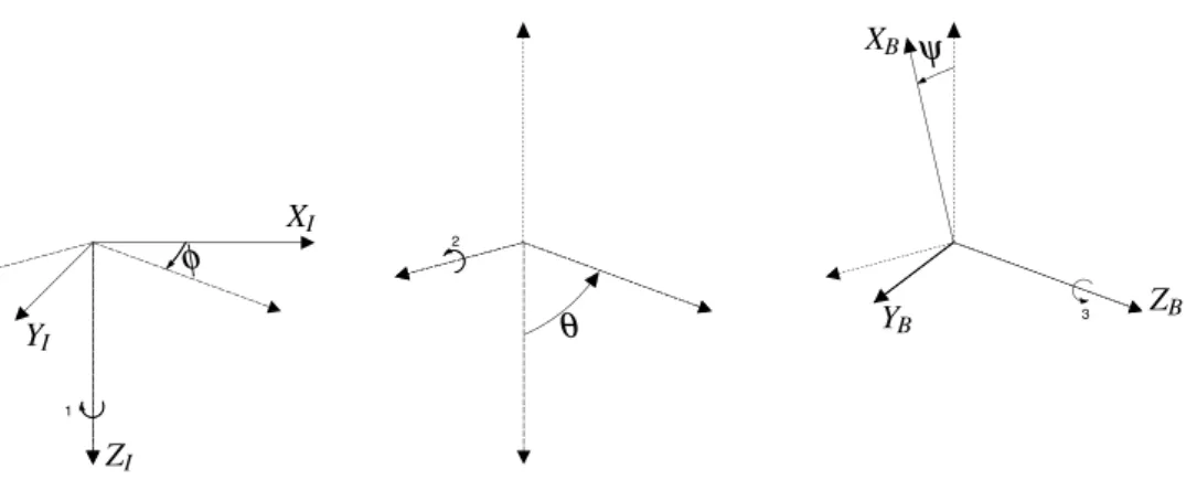
2.2 Sequence of rotations from the inertial frame {I} to the body-fixed frame {B}. Sequence: yaw → pitch → roll (ψ → θ → φ) . . . 11
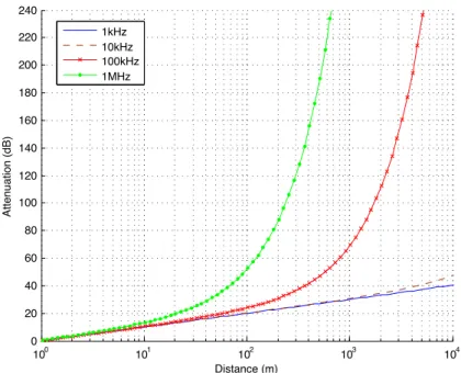
2.3 Attenuation of acoustic waves in seawater. Parameters: salinity = 3.54%, temper-ature = 20oC, sound speed = 1500m/s, pH = 8. . . . 23
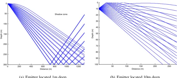
2.4 Multipath originated by refraction and reflections . . . 24
2.5 Autonomous underwater vehicles . . . 24
2.6 Autonomous surface vehicles . . . 25
3.1 MARES thrusters configuration . . . 28
3.2 Sequence of rotations from the inertial frame {I} to the body-fixed frame {B}. Sequence: roll → pitch → yaw (φ → θ → ψ) . . . 31
3.3 The function fρ( ˜φ(t)) . . . 37
3.4 Simulation results: pitch and yaw angles . . . 39
3.5 Simulation results: depth . . . 39
3.6 Simulation results: horizontal position evolution . . . 40
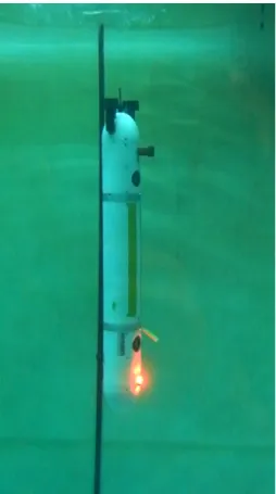
3.7 MARES in vertical pose . . . 41
3.8 Experimental results: pitch and yaw angles . . . 42
3.9 Experimental results: roll angle . . . 42
3.10 Experimental results: depth . . . 42
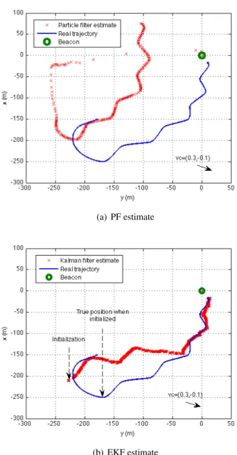
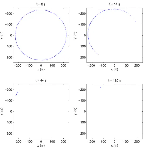
4.1 Comparison between the particle filter and the extended Kalman filter estimates . 54 4.2 Evolution of the 1000 particles for an initialization with the vehicle starting at (x,y) = (−150,−170). The vehicle velocity is u = 1m/s and the currents are (vx,vy) = (−0.2,0.1). . . 56
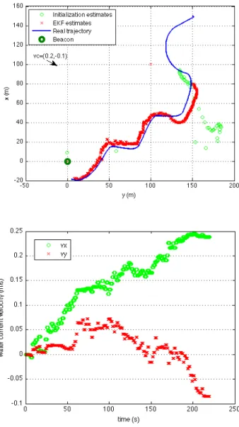
4.3 Position and current velocity estimations . . . 57
4.4 Homing at 2m/s . . . 58
4.5 Evolution of the covariance as a function of the minimum switching period and of the switching covariance. The results were obtained from several simulations performed with the same initial conditions. . . 59
4.6 Ground truth (blue solid line) and estimated trajectories (red dots) as functions of the minimum switching period and of the switching covariance. Surge velocity reference is u = 1m/s and the current velocity is (vx,vy) = (−0.2,0.1) . . . 60
4.7 Homing method . . . 62
4.8 Illustration of the intervals of angles for stability analysis . . . 66
4.9 Upper bound of the invariant set . . . 67
4.10 Results obtained for homing with surge velocity 1.0 meter per second (estimated) and desired approach rateβ = 0.6 (log20110729142857) . . . 70
4.11 Results obtained for homing with surge velocity 1.5 meter per second (estimated)
and desired approach rateβ = 0.7 (log20110803142434) . . . 71
5.1 Controlled states during a hovering maneuver of TriMARES . . . 85
5.2 Position errors and relative angles . . . 88
5.3 Target tracking trajectory. The arrows show the heading of the vehicle plotted at intervals of 10 seconds. . . 97
5.4 Evolution of the horizontal coordinates . . . 97
5.5 Tracking error: center of gravity (CG) and bow relative distances . . . 98
5.6 Relative position of the vehicle (center of gravity (CG)) and relative position of bow with regard to the position reference . . . 100
5.7 Yaw angle . . . 100
6.1 Coordinated mission of Zarco and Gama in La Spezia . . . 114
6.2 Positions of Zarco and Gama resulting from the coordinated mission in La Spezia. The circles indicate the positions of the vehicles at intervals of 30 seconds. . . 115
6.3 Relative positioning error between Zarco and Gama for the trajectory of figure 6.2 115 6.4 Coordinated mission of Zarco and Gama . . . 117
6.5 Relative distance error of Zarco and Gama along the coordinated operation . . . 117
6.6 Coordinated mission of Zarco and Gama . . . 118
6.7 Relative distance error of Zarco and Gama along the coordinated operation . . . 119
6.8 Discrete position references and trajectories of the two autonomous surface vehi-cles (ASVs). The cirvehi-cles indicate the position references. . . 120
6.9 Real and reference relative positions of the two ASVs. Upper: North component. Lower: East component. . . 120
6.10 Time difference between two consecutive successful transmissions of state to the virtual leader . . . 121
7.1 Optimal positions of receivers (circles). The target (cross) is located at the origin. The parameters considered areσi=10−4s ∀i. . . 128
7.2 Metric value as a function of target position as a function of the target position in the plane defined by zt =0. The parameters considered are cs=1500 m/s, σi=10−4s ∀i ∈ {1,...,N}. . . 128 7.3 Error evolution . . . 133 7.4 Step increment . . . 133 7.5 Optimal positioning (σ = 10−4s) . . . 135 7.6 Estimate error (σ = 10−4s) . . . 135 7.7 Optimal positioning (σ = 10−2s) . . . 136 7.8 Estimate error (σ = 10−2s) . . . 136
7.9 Influence ofρ on the metric . . . 142
7.10 Formation of four heterogeneous vehicles . . . 145
7.11 Mean estimated position over a window of 60 sequential estimates . . . 147
7.12 Standard deviation of the estimate . . . 148
7.13 Mean position of the formation and estimated position of the target . . . 149
List of Tables
2.1 Characteristics of navigation sensors/systems . . . 26
C.1 Added mass coefficients . . . 165
C.2 Viscous damping coefficients . . . 165
C.3 Parameters . . . 166
C.4 Inertia tensors . . . 166
D.1 Added mass coefficients . . . 167
D.2 Viscous damping coefficients . . . 168
D.3 Parameters . . . 168
D.4 Inertia tensors . . . 168
E.1 Added mass coefficients . . . 170
E.2 Viscous damping coefficients . . . 171
E.3 Parameters . . . 171
E.4 Inertia tensors . . . 171
F.1 Added mass coefficients . . . 173
F.2 Viscous damping coefficients . . . 174
F.3 Parameters . . . 174
F.4 Inertia tensors . . . 174
G.1 Added mass coefficients . . . 175
G.2 Viscous damping coefficients . . . 176
G.3 Parameters . . . 176
G.4 Inertia tensors . . . 176
Chapter 1
Introduction
Currently, the world demands for the inclusion of robotics in several domains, a demand that has been increasing each day. Motivated by such need, robotics has evolved considerably over the last decades in which intensive and enthusiastic works have been developed by many researchers. Al-though it is based on a core where electrical and mechanical engineering constitute the elementary sciences, the multidisciplinary nature of robotics makes this domain even more challenging.
In a historical perspective, humans have always made use of tools to help themselves to ac-complish an extensive number of tasks. Nowadays, the technology has become an important (indispensable) tool for humans and has evolved, answering to new needs and challenges. By following the same trend, robots have been employed as means of performing undesired or im-possible tasks. They have replaced humans in numerous risky tasks, protecting them from injuries and ultimately saving lives. Several examples can be found in land robotics (space and hearth) (Squyres et al., 2004), industrial robotics (Fukuda and Nakagawa, 1988) and underwater robotics (Antonelli et al., 2008), covering a large number of distinct applications from exploration, mon-itoring and surveillance to transportation, intervention and rescue. The latter references are, of course, just illustrative examples of many works in the different branches of robotics. Not only professional needs have originated robotics solutions but also entertainment and domestic needs have contributed for an important growth of robotic systems.
Nevertheless, the expansion of robotics is yet restrained since most robots are operated only by their designers, experienced specialists or closely related people. However, as the interest of the general public and non-related professionals increases, the interface with the robot must be simple while its operation must be strongly robust and autonomous. These characteristics imply considerable effort during the design process.
Different needs have originated different types of solutions with heterogeneous operation methods specially specified to each problem. Land robots include wheeled and legged robots while water environments have originated surface and underwater vehicles. In the present the-sis, a special focus will be given on marine robotics but most of the subjects tackled here are not constrained to this specific domain.
The underlying subject of the current work is on control and coordination of multiple robots 1
that suffer from real practical constraints. Motivated by scenarios in which the navigation of robots commonly depends on auxiliary equipment coherently deployed on the region of interest, the control and coordination of robots are addressed in order to achieve more dynamic and versatile behaviors.
1.1 Marine robotics
The domain of application of mobile marine robots is broad, comprehending fields that go from science to defence. As for robotics in general, their tasks include operations that require skills that humans do not compile, as well as operations in hazardous or intolerable environments. A large number of specific tasks in different environments has given rise to several types of marine robots. Marine robots can be divided in two large families: surface and underwater robots. The most common applications of marine robots include archaeology, mapping, inspection, environmental data sampling and defence.
Marine robots have taken an important role in underwater archaeology. Common operations require large coverage and the observation of numerous interesting objects with historical rele-vance lying on the bottom of the seas or rivers. The intrinsic constraints of underwater environ-ment such as limited visibility and acoustic attenuation/refractions make vision systems and sonars useless at large distances. The observation of such an environment demands for precise localiza-tion and posilocaliza-tioning. Underwater vehicles play an important role in this context thanks to their ability to approach the site as close as required in order to obtain sufficiently refined data.
The sea floor topology has been studied through bathymetry and mapping in which surface and underwater vehicles have served as platforms to carry the respective payload. Combined with precise localization data, three-dimensional maps can be build for the purpose, thus cultivating the knowledge on the sea bottom and contributing for topography of oceans.
Inspection of moving and stationary platforms has attracted the attention of the industry and of the military community by understanding the capability of robots to perform such a task. Several works have motivated the use of robots for inspection of ship hulls as well as the inspection of offshore oil platforms. The versatility and the sensing capability make the robots instruments of relevant value for those applications.
Not less important is the scientific data harvesting. Oceans, and underwater environments in general, possess unique resources that are probably underexplored because of the particularly hostile conditions. Today, several underwater robots are serving the scientific community by nav-igating over large regions while collecting meaningful data through on-board sensors.
Within the military context yet, marine robots have applications in surveillance, recognition and demining, just to cite a few.
1.1.1 Surface vehicles
Autonomous surface vehicles include autonomous surface crafts (ASCs) and autonomous sail-boats. The first ones are self-propelled by means of thrusters physically coupled to the craft body.
1.1 Marine robotics 3 For ocean applications, their design makes them large enough to remain stable under adverse con-ditions that are caused by wind, currents and waves. Their dimensions are usually above three meters long by one meter large, depending on their shape (monohull, catamaran, trimaran). These dimensions generally leave free space for carrying a relatively large amount of batteries, or fuel, for propulsion and power for electronics. Besides power, ASCs usually employ a set of sensors for measuring velocity, position, wind speed, angles, and are commonly endowed with communi-cation devices.
For what concerns equipment, autonomous sailboats are similar to ASCs. However, instead of using thrusters, their motion relies on the force originated by the wind blowing on one or more sails. Heading is controlled by a combination of one or more rudders placed under the hull and by the orientation of the sails. Although their maneuverability is generally poorer than that of the ASCs, the low power consumption constitutes a major advantage for long trajectories.
The domain of application of autonomous surface vehicles is, at least, as large as the fields that are covered by boats and floating platforms, including (just to cite a few) monitoring, surveillance, rescue and inspection.
1.1.2 Underwater vehicles
There exist two classes of underwater vehicles, namely autonomous underwater vehicles (AUVs) and remotely operated vehicles (ROVs). As their name suggest, AUVs operate autonomously and generally do not contemplate any physical connection to control stations when they navigate. In opposition to AUVs, one or more operators control the ROVs by means of communications that a tether usually grants. A large variety of ROVs exists nowadays, mainly differing on dimen-sion, actuation and payload. Their characteristics are determined according to their missions. The dimensions and weight of common commercial ROVs range from few centimeters with few kilo-grams to few meters and a few tons. ROVs for intervention and deep operation typically have larger dimensions and weight than shallow water inspection ROVs. ROVs are usually designed to navigate in confined regions where on-line observations and remote intervention are required. On the surface, an operator commands the motion of the robot and other actuation tools, which are carried along, by means of a connecting tether that can also be used to supply power to the ROV. A tether can have considerable diameter and length. Since the reachable area is limited by the length of the cable, its presence makes the operation of this type of robots conditioned. In ad-dition, the drag forces become significantly large with long tethers and the corresponding weight induces forces and moments on the robot.
AUVs, also known as unmanned underwater vehicles (UUVs), have been conceived to access underwater environments and overcoming some of the limitations of ROVs. According to An-tonelli et al. (2008), there are approximately 200 different AUVs operating in the world. Their shapes differ on details but commonly converge to streamlined bodies such as torpedoes, spheres, ellipsoids or flat shapes because of their low damping characteristics in viscous environments. AUVs include propelled and buoyancy driven vehicles. The motion of the first ones is driven by propellers and (possibly) control surfaces while the seconds make use of fins and a compartment
where a gas is compressed and decompressed in order to vary the buoyancy of the body. During ascent and descent, the fins are controlled in a way that makes them induce lift and therefore create longitudinal motion. This type of vehicles are commonly referred to as gliders. While their power consumption is very low, the low speed at which they are able to move (typical speeds are about 0.3m/s) make their operation difficult under large currents or turbulent waters.
1.2 Control and coordination
The motion of vehicles is guaranteed by means of actuators. In unmanned vehicles, actuation commands are either given remotely or automatically by means of controllers that are used to ensure that the desired motion of the vehicle is obtained. Nevertheless, it is frequent to find combinations of these in order to reduce the operation complexity and/or to improve performances according to any given performance metric that may consider precision, efficiency or stability, for example. Besides performance improvement, deterministic behaviors and robustness over long time operations are some of their additional characteristics that are particularly appreciated.
In the context of marine vehicles, nonlinear controllers have the capability to warrant all such characteristics. Provided that the dynamics of marine vehicles is strongly nonlinear, it is expected that nonlinear controllers have some advantages over linear and artificial intelligence based con-trollers. In the former case, linear automatic controllers can not ensure stability and performing operation over a broad state range. In many cases, artificial intelligence based controllers, which include neural networks and fuzzy controllers, are not supported by a theoretical background that enables stability analysis and therefore can not warrant the same determinism as that of nonlinear controllers.
Robotic coordination, and more generally cooperation, are means of taking advantage of sev-eral distributed robots that may have different and complementary capabilities. A multitude of applications and motivating examples can be found in the literature to emphasize the need for co-ordination in robotics. Coco-ordination is used to obtain coherent motion of vehicles that makes the overall system, which is composed of the robots in the team, perform according to the objectives of a given mission.
In coordinated operations, robots require exchanging information on relevant quantities that define their states with regard to the operation objectives. This exchange is obtained from sensing or communications, or a combination of both. The stability and the robustness of the coordinated operations under constraints imposed by current technological solutions, which contemplate de-layed, low rate and intermittent exchange of information, has attracted the attention of several researchers recently, encouraged by the current challenges and needs posed in robotics and espe-cially in marine robotics.
1.3 Motivation 5
1.3 Motivation
The intrinsic characteristics of marine environment frequently make the operations risky, espe-cially underwater. There is no, and there will not be, totally secure operations in the water but a recent trend stimulated by several researchers has shown that it is possible to improve the naviga-tion through distributed, cooperating robots.
Parker (2008) summarizes the following:
“The most common motivations for developing multirobot system solutions are that:
1. the task complexity is too high for a single robot to accomplish; 2. the task is inherently distributed;
3. building several resource-bounded robots is much easier than having a single powerful robot;
4. multiple robots can solve problems faster using parallelism; and
5. the introduction of multiple robots increases robustness through redundancy. ” One can quickly identify several items that correspond to cooperative improvement of nav-igation of vehicles, namely items 2, 3 and 5. To our knowledge, there is yet no solution that cooperatively solves the problem of navigation of underwater vehicles with bounded error for an unlimited region without human intervention. Moreover, very interesting results have been ob-tained for cooperation of ground, and more generally surface, robots but the most of these methods can not be directly applied to underwater robotics mainly due to communication constraints. Tak-ing such constraints into consideration, the need to develop new methods has emerged. Those methods would solve cooperative, bounded error navigation.
The natural constraints found in underwater environments makes the navigation of autonomous robots difficult. In opposition to surface, land and aerial robots whose localization problems are generically easier to solve thanks to the broad current sensing technology, underwater naviga-tion poses several challenges especially when accurate, bounded error localizanaviga-tion is required. As previously stated, most current state-of-the-art solutions for precise bounded error underwater navigation are time-consuming and sometimes expensive when they imply the deployment of sev-eral equipments, such as beacons. Additionally, the localization precision varies according to the relative position of the AUV with respect to the beacons.
The energy autonomy of underwater vehicles has been growing and it is now possible to ad-dress several scenarios that require long range/large area missions. In those cases, static acoustic beacons are of limited use and perception-based navigation is extremely complex due to the fea-tureless nature of many underwater environments.
Robot cooperation becomes a valid option to overcome such constraints. By exploring the concept of navigation aid systems, the human intervention can be significantly reduced. Ulti-mately, deployment could be reduced to launching a small group of robots from the coast/margin.
Additionally, the operation area would be limited only by the energy autonomy available in each robot.
The present work is established around control and coordination of marine robots. Motivated by navigation aided robotics applications, for which navigation aid robots have to coordinate their operations to provide meaningful measurements or data to one or more survey robots, robust con-trol methods and coordination schemes must be derived for the team of robots. The intrinsic practical constraints found in underwater environments should be regarded with particular atten-tion. These generally make the navigation problems more challenging than in surface, aerial or ground robotics mainly because of the sensing limitations and of the communication constraints.
Different robots with different shapes and different actuator configurations originate different dynamics. Each robot must be regarded singularly and its motion must be governed by proper, well defined control laws. Although different, the control algorithms can be built upon a common framework. This type of approach enables the possibility of common interactions and quick recon-figurations for defining new roles. Moreover, the definition of a set of common elementary motion primitives makes it possible to achieve coordination at a (desired) higher level. The capability of coordinated vehicles to distribute resources over a region of interest can then be exploited to co-operatively accomplish goals that may include cooperative tasking or performances improvement according to any given metric.
1.4 Contributions
This thesis builds upon the background of control, coordination and navigation. Mainly motivated by robust control of marine vehicles, multi-vehicle operations and robot aided navigation, several steps towards fully autonomous coordinated operations and coordinated localization are made. The contributions of this thesis are summarized as follows:
• Design of a control law to stabilize hovering AUVs in the vertical pose - as a demonstration of the capabilities of the application of nonlinear control tools to achieve desired behaviors, a control law is derived to stabilize a hovering AUV at pitching angles of ±90◦.
• Development of a new localization method using range-only measurements combined with homing of a vehicle - using estimation, an extended Kalman filter (EKF) and a particle filter (PF) are implemented to solve the localization problem. The estimate is then combined with a control law that drives the vehicle to the beacon. The estimate confidence is used to modify the trajectory of the vehicle, intending to improve the estimate.
• Design of a gradient-tracking guidance law to home a vehicle using range-only measure-ments - localization is dispensable to home a vehicle to a beacon to which it is able to measure ranges. A guidance law is derived to home the vehicle with surge and yaw degrees of freedom (DOFs) and its stability is proven .
1.5 Organization of the thesis 7 • Development of a generic control framework for coordinated autonomous vehicles - by adopting a layer perspective, three control loops are proposed to stabilize velocity, position and the configuration and position (center of mass) of the formation.
• Derivation of a set of tools to compute velocity and position errors boundedness - in the presence of model uncertainties and measurements errors, it is expectable that model-based control and guidance laws can not guarantee null error in steady state. As such, relevant results have been derived to assess such tracking errors.
• Extension and adaptation of the coordination scheme proposed by Egerstedt and Hu (2001) - the centralized control method is made tolerant to communication intermittences and is adapted so that the formation can hold its position. Moreover, the method is built so that, if the local control and guidance laws warrant appropriate tracking, the relative positioning errors are upper bounded and configurable.
• Derivation of the three-dimensional optimal positions of sensors in time-of-arrival (TOA)-based localization of a sound source underwater - two cases are addressed for this problem: 1) the optimal unconstrained positions of sensors to minimize the volume of the confidence region around the sound source; 2) the plane-constrained optimal positions of sensors to estimate the three-dimensional position of a sound source underwater.
1.5 Organization of the thesis
The remainder of this thesis is organized as follows. Chapter 2 gives a brief overview on control tools and estimation algorithms to support the following chapters. Additionally, and to motivate several solutions adopted in this thesis, a technological overview on the current navigation solu-tions is provided and the autonomous vehicles that have been employed throughout the develop-ment of the work presented in this thesis are introduced. Chapter 3 presents an application example where the control of a hovering AUV at pitching angle ±90◦is addressed. At the kinematics level,
the localization and the homing of an autonomous vehicle with controllable surge and yaw rate are addressed in chapter 4 as basic exercise of coordination. Two methods are proposed for homing the vehicle resorting only to range measurements. Firstly, homing is obtained by means of com-bined estimation and control. Then, following a sensor-based approach, a guidance law is derived to home the vehicle without any position estimate. Both the methods presume the existence of a lower loop that is capable of tracking the velocity reference provided. This velocity control loop is formalized in chapter 5. This chapter presents a model-based control law where possible mod-elling errors may be introduced. The upper bounds on velocity tracking are derived. The velocity inner loop is then employed in a target tracking and station-keeping guidance law for autonomous marine vehicles. These two basic layers are subsequently used to track references given by a coor-dination scheme presented in 6 that is capable of handling communication constraints and ensures an upper bounded relative position error under appropriate tracking of the vehicles. Finally, the
coordination of marine vehicles is applied to the coordinated tracking and localization of an un-derwater sound source in chapter 7, where the optimal positions of acoustic receivers are derived. Two cases are addressed: unconstrained positioning of sensors in three-dimensional space and plane-constrained positioning for three-dimensional optimal estimation.
Whenever it is convenient, at the beginning of each chapter, the main background and the related works are presented. Results of simulations, experimental data and the respective analysis are provided at the end of each chapter.
Chapter 2
Overview
Before addressing specific problems of marine vehicle automatic guidance and control, it is im-portant to expose the main tools used in this thesis. Firstly, this chapter aims at providing a brief overview on mathematical dynamic and kinematic models and on control tools closely related to the solutions adopted in the next chapters. Secondly, the fusion1of measurements is addressed.
In real applications, sensors provide meaningful measurements on a multitude of variables that are subsequently fused to guess the state estimate. This fusion has to be performed for two main reasons: noise affects the measurements and the direct utilization of measurements to determine the state may lead to very noisy state estimates, which may significantly degrade the control per-formances; or, the state is not directly measurable (there is no closed, direct relationship between the state and the observations) and a filter that uses (fuses) the relevant measurements has to be employed to infer the state. In robotics, these filters are commonly utilized for both smoothing and state estimation. For completeness and to support the forthcoming chapter, the main concepts and formulation for two widely-used filters are presented, specifically, the extended Kalman fil-ter (EKF) and the particle filfil-ter (PF). In a more technological perspective, this chapfil-ter ends with an overview on the commonly employed solutions in marine localization, and on their constraints, as well as a brief presentation of autonomous vehicles that have served as development and testing platforms.
2.1 Notation
Throughout this document, the following notation is adopted for simplicity and compactness. For brevity, as in Fossen (1994), the trigonometric functions are denoted s · = sin(·), c · = cos(·) and t · = tan(·). For vectors, the notation [·]idenotes the ith entry, [·]i jdenotes the entry of a matrix on
the ith row and jth column. The representation | · | is used to denote the absolute value of a scalar or a vector. In the latter case, all the resulting entries are the absolute values of the components of the vector. The notation (·)T is used to express the transpose of a matrix or vector. Similarly,
1fusion of measurements is the process of combining different or similar measurements obtained from different
sensors with the aim of reaching a better estimate for a given quantity
