Department of Mechanical Engineering Integrated Masters in Mechanical Engineering
CFRP joints with hybrid laminates
metal-carbon fibre
Submitted by:
João Luís Cardoso Henriques Martins
Supervised by:
Lucas Filipe Martins da Silva
Co-supervised by: Ricardo João Camilo Carbas
Abstract
The aerospace and automotive industries are at the forefront with regard to technological advances in several areas of engineering. The materials and their bonding processes are in constant evolution, with special attention to the use of composite materials and structural adhesives. The fibre-metal laminates (FML) are hybrid materials which, as the name implies, consist of a structure composed by metal laminates and fibre reinforced polymer layers. This composite material arose in the 70’s with the aim of strengthening a metal structure. A compromise was achieved between the best features of metallic materials, such as impact strength and good machinability, and the most interesting properties of fibre reinforced polymers, such as high mechanical strength, good resistance to fatigue and corrosion, among others. FMLs have been the target of several investigations by major aerospace companies, such as Airbus and Boeing, in order to replace certain metallic materials as constituents of structural components of vital importance in their aircrafts.
The theme of this thesis is based on the use of a similar concept to the FML to improve the peel strength of composite materials, as well as the adhesive joint strength itself that uses this material as an adherend. Using an epoxy matrix reinforced with carbon fibres as the composite material, its structural modification was performed by inserting one or two titanium sheets, during the production of the FML, in order to improve the through thickness properties of the composite. The main objective is to identify which configuration allows to obtain the best mechanical properties, when compared to the reference one, composed entirely of carbon fibre reinforced plastic (CFRP).
In order to find out the best configuration, four different designs were tested through tensile tests of single lap joints with two distinct overlaps – 12.5 and 50 mm. To predict the failure load and the failure mode of each one of the joints, several numerical models, using finite element analysis, were created to simulate the tensile tests of the adhesive joints experimentally manufactured, through the commercial software Abaqus®. The numerical models were improved for the purpose of correctly predicting the failure load and the joint strength.
It was verified that the delamination in the CFRP was less severe with the use of hybrid adherends constituted by titanium and CFRP. In addition, higher failure loads were obtained, as well as a greater joint’s strength. An interesting failure mode was obtained
concept of safety, important to the aerospace industry.
With the purpose of optimizing the joint which featured the best behavior when tensile tested, the influence of the joint’s thickness, the proportion of materials and the test conditions imposed was analyzed. It was confirmed that the failure load and the peel stresses along the joint were not significantly influenced by the joint’s thickness or the percentage of titanium. However, when these joints were tested under impact conditions, the obtained failure load was expressively higher than the values achieved under static conditions.
A comparison between FMLs with different metallic sheets, aluminium and titanium, was made. The titanium presented the highest failure load for both static and impact conditions.
Resumo
As indústrias aerospacial e automóvel encontram-se na vanguarda no que diz respeito aos avanços tecnológicos em diversas áreas da engenharia. As áreas dos materiais e dos seus processos de ligação apresentam-se em constante evolução, com especial atenção para a utilização de materiais compósitos e de adesivos estruturais. Os fibre-metal laminates, também designados por FML, são materiais híbridos que, tal como o nome indica, consistem numa estrutura composta por laminados metálicos e camadas de um polímero reforçado com fibras intercalados entre si. Este material compósito surgiu na década de 70, numa primeira instância, com o intuito de reforçar uma estrutura metálica. Assim, era obtido um compromisso entre as melhores características dos metais, como por exemplo a resistência ao impacto e boa maquinabilidade, e as propriedades mais interessantes dos polímeros reforçados com fibras, como a elevada resistência mecânica, boa resistência à fadiga e à corrosão entre outras. Os FMLs têm sido alvo de investigações por parte de grandes empresas aerospaciais, como a Airbus e a Boeing, no sentido de substituirem certos materiais metálicos como constituintes de componentes estruturais de crucial importância nas suas aeronaves.
O tema desta tese assenta na utilização de um conceito similar ao do FML para melhorar a resistência ao arrancamento de materiais compósitos, bem como a resistência da própria junta adesiva que utiliza esse material como aderente. Assim sendo, utilizando como material compósito uma matriz epóxida reforçada com fibras de carbono foi realizada a sua modificação estrutural ao introduzir um ou dois laminados de titânio durante a produção dos FML, de forma a melhorar as propriedades transversais do compósito. O principal objectivo consiste em identificar qual a configuração que permite obter as melhores propriedades mecânicas, quando comparada com a configuração de referência, constituída unicamente por polímero reforçado com fibras de carbono.
De forma a descobrir qual a melhor configuração, foram testadas quatro tipos de juntas através de ensaios de tração de juntas de simples sobreposição com dois comprimentos de sobreposição dferentes – 12.5 e 50 mm. Para obter uma previsão da força de rotura e da superfície de falha de cada configuração, foram criados diversos modelos numéricos, recorrendo à análise de elementos finitos, com o intuito de simular os ensaios de tração das juntas adesivas para as diferentes configurações, através do software comercial Abaqus®. Os modelos numéricos foram aperfeiçoados a fim de preverem o melhor possível a força de
híbridos de titânio e de CFRP. Para além disso, maiores forças de rotura foram obtidas, bem como uma maior resistência da junta. Um modo de falha interessante foi obtido, caracterizado por uma falha adesiva na interface titânio-CFRP que levou a uma rotura progressiva da junta o que pode ser considerado bastante relevante no que concerna ao conceito de segurança defendido pela indústria aerospacial.
Com o propósito de optimizar a junta que apresentava um melhor comportamento quando testada à tração, foi analisada a influência da espessura, da proporção dos materiais e ainda da solicitação imposta. Confirmou-se que a força de rotura e as tensões de arrancamento ao longo da junta não eram, significativamente, influenciadas pela espessura da junta nem pela percentagem de titânio. No entanto, quando estas juntas eram testadas sob condições de impacto, a força de rotura obtida apresentava um valor significativamente maior àqueles alcançados em condições estáticas.
A comparação entre os FMLs usando diferentes metais, alumínio e titânio, foi realizada. O titânio apresentou os melhores valores de força de rotura para ambas as condições de teste.
Acknowledgments
I would like to thank, primarily, Ricardo Carbas for his inexhaustible patience and availability during this semester. Also recognize that without his guidance and commitment this project would not be as successful as it was.
I would also like to thank Professor Lucas da Silva, for sharing his enormous knowledge and for challenging me with numerous tasks that made this investigation thesis even more motivating.
I would particularly like to show my endless gratitude to all members of ADFEUP, including Eduardo, José, Daniel and both Ana, for all opinions shared and all tips given during this project.
To my Master’s colleagues, Mário and Paulo, I recognize that their help was of extreme importance.
I would like to thank the LADs, Ambrósio, Álvaro, Bernardo, Rocha, Manuel, José, Jolie, Antelo, Maria, Nando, Mário and Roque, for being there whenever I needed and for supporting me through this important journey.
I would like to especially thank my girlfriend, Catarina, for her patience through this semester, as well as her crucial advices given in every single decision I had to make.
Finally, to my father, my mother and my siblings, for the unconditional support and for turning the dream of being an engineer an eternal reality.
Abstract ... ii
Resumo ... iv
Acknowledgments ... vi
Nomenclature ... ix
List of figures ... xi
List of tables ... xiv
1. Introduction ... 1
1.1. Background and motivation ... 1
1.2. Objectives ... 3
1.3. Research methodology ... 3
1.4. Outline of the thesis ... 4
2. Literature Review... 5
2.1. History of composite materials ... 5
2.2. Fibre reinforced composites ... 7
2.2.1. Matrices and fibres ... 7
2.2.2. Carbon fibre reinforced polymers ... 7
2.2.2.1. Mechanical properties and applications of CFRP’s ... 7
2.2.2.2. Failure modes and failure mechanics of CFRP’s ... 10
2.3. Adhesive bonding ... 11
2.3.1. Joint configurations ... 12
2.3.2. Failure modes in adhesive joints ... 13
2.3.3. Techniques to reduce the peel stresses in composite materials ... 15
2.3.4. Fibre metal laminates ... 17
2.4. Strength prediction of adhesively bonded joints ... 19
2.4.1. Numerical solutions ... 19 3. Experimental details ... 23 3.1. Adhesive ... 23 3.2. Adherends ... 24 3.2.1. CFRP ... 25 3.2.2. Titanium alloy ... 25 3.3. Specimens configurations... 26 3.4. Specimens manufacture ... 27 3.4.1. CFRP plates ... 27
3.4.2. Surface treatment of the titanium alloy ... 30
3.4.3. Surface treatment influence ... 32
3.4.4. Manufacture of CFRP-Titanium laminates ... 34
3.4.5. Manufacture of single lap joints ... 35
3.4.6. Testing conditions ... 38 4. Experimental Results ... 40 4.1. CFRP-only SLJs ... 40 4.1.1. 12.5 mm overlap length ... 40 4.1.2. 50 mm overlap length ... 41 4.2. CFRP-Ti-CFRP SLJs ... 42 4.2.1. 12.5 mm overlap length ... 42 4.2.2. 50 mm overlap length ... 43 4.3. Ti-CFRP SLJs ... 44 4.3.1. 12.5 mm overlap length ... 44 4.3.2. 50 mm overlap length ... 45 4.4. Ti-CFRP-Ti SLJs ... 47 4.5. Comparison of SLJs’ results ... 49 4.5.1. 12.5 mm overlap SLJs ... 49 4.5.2. 50 mm overlap SLJs ... 50
5. Numerical Analysis ... 52
5.1. Model description ... 52
5.2. Triangular cohesive law vs Trapezoidal cohesive law ... 55
5.3. Numerical results ... 59 5.3.1. CFRP-only SLJs ... 60 5.3.1.1. 12.5 mm overlap length ... 60 5.3.1.2. 50 mm overlap length ... 61 5.3.2. CFRP-Ti-CFRP SLJs ... 62 5.3.2.1. 12.5 mm overlap length ... 62 5.3.2.2. 50 mm overlap length ... 64 5.3.3. Ti-CFRP SLJs ... 65 5.3.3.1. 12.5 mm overlap length ... 65 5.3.4. Ti-CFRP-Ti SLJs ... 66 5.3.4.1. 50 mm overlap length ... 66 6. Discussion ... 68
7. Optimization of Ti-CFRP-Ti single lap joints ... 72
7.1. Different thicknesses ... 72
7.2. Distinct proportion of materials ... 74
7.3. Impact conditions ... 76
8. Conclusions ... 80
9. Future work ... 82
Acronyms
• ARALL – Aramid reinforced aluminium laminates • CBBM – Compliance-based beam method
• CFRP – Carbon fibre reinforced polymer • CNFs – Carbon nanofibres
• CTE – Coefficient of thermal expansion • CZE – Cohesive zone elements
• CZM – Cohesive zone model • DCB – Double cantilever beam • ENF – End notched flexure • FEA – Finite elements analysis • FEM – Finite elements method • FML – Fibre metal laminates • FRP – Fibre reinforced polymer • GLARE – Glass reinforced aluminium • IA – Inter adherend
• SLJ – Single lap joint
• TAST – Thick adherend shear test • TDCB – Tapered double cantilever beam
Symbols
• Al – Aluminium • b – Width of the joint • CO2 – Carbon dioxide
• E – Young’s Modulus • G – Shear modulus
• GIC – Fracture energy in mode I
• GIIC – Fracture energy in mode II
• l – Overlap length • P – Load
• t – Thickness of the adherend • Ti – Titanium
• δ - Displacement • τ – Shear stress • υ – Poisson’s ratio
Figure 1 - Composition of A350 XWB [4]... 1
Figure 2 - Composition of Boeing 787 "Dreamliner" [5] ... 1
Figure 3 - FML configuration [6] ... 2
Figure 4 - Mongolian bow [8] ... 5
Figure 5 – Fiberglass [9] ... 5
Figure 6 - Fiberglass boat [11] ... 6
Figure 8 - Carbon fibre reinforced epoxy matrix – prepreg form [15] ... 8
Figure 7 - Prepreg production process [14] ... 8
Figure 9 - Automotive CFRP's applications [17] ... 9
Figure 10 – Failure modes of fibre reinforced polymers [19] ... 10
Figure 11 - Adhesive bonded joints [22] ... 12
Figure 12 - Typical loads of an adhesive joint: a) Normal stress; b) shear stress; c) cleavage stress; d) peel stress [21] ... 13
Figure 13 - Failure mode for adhesives joints [23] ... 13
Figure 14 - Delamination of a FRP's adherend [24] ... 14
Figure 15 - Internal taper and adhesive fillet [26] ... 15
Figure 16 - Reduction of transverse stresses by internal taper and adhesive fillet [26] ... 15
Figure 17 - Z-pins technique [27] ... 16
Figure 18 - Crack growth resistance (R-) curves for the unreinforced and through-thickness reinforced laminates containing 0.82 vol% CNFs and/or 0.5 vol% z-pins under quasi-static [28] ... 16
Figure 19 - Inter-adherend-fibre joint [29] ... 17
Figure 20 - Classification of FMLs based on metal plies [31] ... 18
Figure 21 - Cohesive elements to simulate zero thickness failure paths [32] ... 21
Figure 22 - CZM laws with triangular, exponential and trapezoidal shapes available in Abaqus® [53] ... 22
Figure 23 - Cure cycle for the adhesive AF 163-2K [54] ... 23
Figure 24 - Selected configurations for FML manufacturing... 26
Figure 25 - Other possible FML configurations ... 26
Figure 26 - Application of releasing agent to the mould components ... 27
Figure 27 - Pre-heating of the CFRP layers with a hot air gun ... 28
Figure 28 - Cure cycle for CFRP plates ... 29
Figure 29 - Hot plates press machine INTOCO ... 29
Figure 30 - Diamond disc cutting from model DV 25 Batisti Meccanica ... 29
Figure 32 - Loading scheme of traction test in mode I ... 32
Figure 33 – Most representative curve for Mode I traction test ... 33
Figure 34 - Typical failure of the samples in mode I traction test: (a) adhesive failure in Ti-CFRP interface; (b) cohesive failure in Ti-CFRP (delamination) ... 33
Figure 35 - Stacking of the titanium laminates over the CFRP plate ... 35
Figure 36 - SLJs geometry (mm) [55] ... 36
Figure 37 - Adhesive in film placed on one adherend ... 36
Figure 38 - SLJs bonding ... 37
Figure 39 - MTS® model 810 ... 38
Figure 40 - Video system setup to observe the delamination phenomenon ... 39
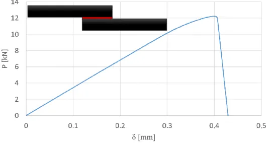
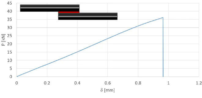
Figure 41 - Load vs displacement typical curve of a CFRP-only SLJ with a 12.5 mm overlap ... 40
Figure 42 - Typical failure surface of 12.5 mm overlap CFRP-only SLJs ... 40
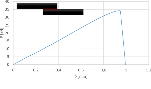
Figure 43 - Load vs displacement typical curve of a CFRP-only SLJ with a 50 mm overlap . 41 Figure 44 - Typical failure surface of 50 mm overlap CFRP-only SLJs ... 41
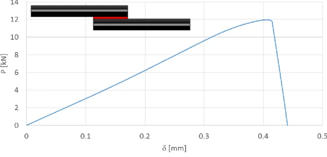
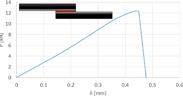
Figure 45 - Load vs Displacement typical curve of a CFRP-Ti-CFRP SLJ with a 12.5 mm overlap ... 42
Figure 46 - Typical failure surface of 12.5 mm overlap CFRP-Ti-CFRP SLJs ... 43
Figure 47 - Load vs displacement typical curve of a CFRP-Ti-CFRP SLJ with a 50 mm overlap ... 43
Figure 48 - Typical failure surface of 50 mm overlap CFRP-Ti-CFRP SLJs ... 44
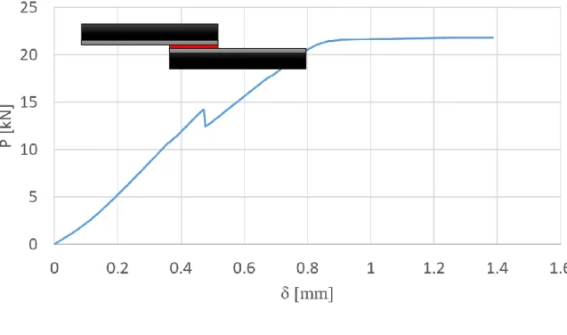
Figure 49 - Load vs Displacement typical curve of a Ti-CFRP SLJ with a 12.5 mm overlap . 45 Figure 50 - Typical failure surface of 12.5 mm overlap Ti-CFRP SLJs ... 45
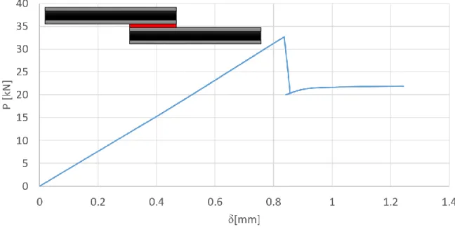
Figure 51 - Load vs displacement typical curve of a Ti-CFRP SLJ with a 50 mm overlap ... 46
Figure 52 - Failure surface of a 50 mm overlap Ti-CFRP SLJ ... 46
Figure 53 - Load vs displacement typicalcurve of a Ti-CFRP-Ti SLJ with a 50 mm overlap . 47 Figure 54 - Failure surface of a 50 mm overlap Ti-CFRP-Ti SLJ ... 48
Figure 55 - Distribution of CZE layers throughout the SLJ ... 52
Figure 56 - Schematic view of the physical boundary conditions in Abaqus® ... 53
Figure 57 - Schematic view of the thermal predefined field ... 53
Figure 58 - Ti-CFRP adherend's bending due to thermal stresses: a) Experimentally; b) Numerically ... 54
Figure 59 - Vertical displacement suffered by both adherends ... 54
Figure 60 - SLJ square mesh with 0.2 mm refinement ... 55
Figure 61 – AF 163-2K P-δ curves [55] ... 56
Figure 67 – Numerical P-δ curve vs experimental P-δ curve for a 12.5 mm overlap CFRP-only SLJ ... 60 Figure 68 - Numerical failure surface of 12.5 mm overlap CFRP-only SLJ... 61 Figure 69 - Numerical P-δ curve vs experimental P-δ curve for a 50 mm overlap CFRP-only SLJ ... 61 Figure 70 - Numerical failure surface of 50 mm overlap CFRP-only SLJ... 62 Figure 71 - Numerical P-δ curve vs experimental P-δ curve for a 12.5 mm overlap CFRP-Ti-CFRP SLJ ... 63 Figure 72 - Numerical failure surface of 12.5 mm overlap CFRP-Ti-CFRP SLJ ... 63 Figure 73 - Numerical P-δ curve vs experimental P-δ curve for a 50 mm overlap CFRP-Ti-CFRP SLJ ... 64 Figure 74 - Numerical failure surface of 50 mm overlap CFRP-Ti-CFRP SLJ ... 64 Figura 75 - Numerical P-δ curve vs experimental P-δ curve for a 12.5 mm overlap Ti-CFRP SLJ ... 65 Figure 76 - Numerical failure surface of 12.5 mm overlap Ti-CFRP SLJ ... 66 Figure 77 - Numerical P-δ curve vs Experimental P-δ curve for a 50 mm overlap Ti-CFRP-Ti SLJ ... 67 Figure 78 - Numerical failure surface of 50 mm overlap Ti-CFRP-Ti SLJ ... 67 Figure 79 - Comparison between FEA predictions and experimental results for the failure load of 12.5 mm overlap SLJs ... 68 Figure 80 - Comparison between FEA predictions and experimental results for the failure load of 50 mm overlap SLJs ... 70 Figure 81 – Comparison between different Ti-CFRP-Ti adherend thicknesses in terms of failure load ... 72 Figure 82 - Comparison between different Ti-CFRP-Ti adherends’ thicknesses in terms of peel stresses ... 73 Figure 83 - Comparison of the failure load between different titanium laminates thickness in Ti-CFRP-Ti joints ... 74 Figure 84 –Comparison of the peel stresses between different titanium laminates thickness in Ti-CFRP-Ti joints ... 75 Figure 85 - Schematic view of the physical boundary conditions for SLJs under impact conditions in Abaqus® ... 76 Figure 86 – Load vs Time curves for all SLJs under impact conditions ... 77 Figure 87 – Comparison of the failure load between quasi-static and impact conditions ... 78 Figure 88 – Failure mode of CFRP-only and CFRP-Ti-CFRP SLJs under impact conditions 78 Figure 89 - Failure mode of Ti-CFRP-Ti SLJs under impact conditions ... 78 Figure 90 - Comparison between Ti-CFRP-Ti and Al-CFRP-Al failure loads under quasi-static and impact conditions ... 79
List of tables
Table 1 – Most important families of adhesives and their properties [21] ... 11
Table 2 – AF 163-2K mechanical properties [55] ... 24
Table 3 – Orthotropic components for a unidirectional CFRP ply [56] ... 25
Table 4 – Mechanical properties of Ti-6Al-4V alpha-beta, annealed [58] ... 25
Table 5 – Failure load and type of failure for joints with a 12.5 mm overlap ... 49
Table 6 - Failure load and type of failure for joints with a 50 mm overlap ... 50
Table 7 – Cohesive parameters for CFRP interlaminar failure [55]... 53
Table 8 – Failure type obtained experimentally and numerically for the 12.5 mm overlap joints ... 69
Table 9 - Failure type obtained experimentally and numerically for the 50 mm overlap joints ... 71
1.1. Background and motivation
The use of metallic materials has been replaced, throughout the years, by other materials that can offer interesting mechanical properties allied with a lower weight, which is one of the most wanted characteristics in aeronautical and aerospace industries. These materials are called composite materials.
The first composite materials were too expensive and those industries continued to prefer metallic alloys as aluminium or steel alloys. However, today we are able to find very good prices that allow the continuous bet in composite materials. For instance, the airbus A380 offers the lowest cost per seat in aerospace industry using advanced aluminium alloys (fuselage and wings) and composite materials in other structures as the centre wing box’s primary structure, wing ribs or rear fuselage section [1]. The use of composite materials results in a reduction of fuel consumption per passenger and CO2 emission which means a significant financial saving. Actually, the percentage of composite materials in the newest aircrafts can reach over 50%, like in A350 XWB and Boeing 787 “Dreamliner” aircrafts [2, 3], as seen in Figures 1 and 2.
Figure 1 - Composition of A350 XWB [4]
This group of materials shows some mechanical disadvantages in some directions due to their anisotropy. Nevertheless, they constitute the highest percentage of aircraft’s materials which is explained not only with the advance of adhesive bonding technology but also with the invention of some techniques to increase the mechanical behavior through the weakest directions.
The adhesive bonding evolution have occurred parallelly with the growth of composite materials. Due to the decrease in their mechanical through thickness properties, the use of holes in order to bond two substrates with bolts or rivets must be avoided, which consents the election of adhesive bonding as ideal. This bonding process allows the achievement of a higher stiffness and a more uniform stress distribution, besides presenting a extremely low weight, in comparison with the use of bolts or rivets. However, adhesive bonding presents some disadvantages, such as the possibility of occurring delamination of the CFRP due to the peel loadings that adhesively bonded joints experience. Therefore, there are also some techniques that allow the improvement of these properties.
One of the techniques used to improve the mechanical properties through the thickness direction is the use of a similar concept of FML (Figure 3).
The study of these FML materials showed that the influence of the metal sheets was very positive by reducing significantly the fatigue crack growth rates in adhesive bonded sheet materials [7].
1.2. Objectives
As said before, the main subject of this thesis is to study the influence of titanium laminates when used as a reinforcement of CFRP substrates. The concept is similar to that used in fibre metal laminates.
Therefore, the main objective is to find the best FML configuration that offers the optimal improvement related to peel strength of the composite and also joint strength of composite adhesive joints.
To test and find that optimal configuration, several numerical and experimental studies were made. The CFRP composite suffered a hybridization through its thickness, by including sheets of titanium. The combinations were tested since the only CFRP laminate until the optimal configuration.
1.3. Research methodology
The following planning was done:
a) Literature review on composite materials, mostly carbon fibre and FML, adhesive bonding, titanium laminates and SLJ’s failure mechanisms;
b) State of the art, focusing in FML material and its applications;
c) Surface treatment of titanium laminates, manufacture of FML substrates and specimen’s tests (Mode I);
d) Numerical simulation of the tensile tests made with SLJs using Abaqus CAE software to validate the experimental data;
e) Performance of experimental tests of SLJs for different combinations Ti-CFRP and analysis of the results;
f) Numerical optimization of FML’s configuration in order to find the best one that gives the most interesting mechanical properties to the substrates.
1.4. Outline of the thesis
The outline of the thesis will be described by chapter. 1. Introduction;
2. Literature review on composite materials, adhesive bonding, failure modes of composite and adhesives;
3. Experimental details; 4. Experimental results; 5. Numerical analysis; 6. Discussion;
7. Optimization of SLJs with different adherends thicknesses, distinct proportion of materials and under impact conditions;
8. Conclusions; 9. Future work;
2.1. History of composite materials
The first uses of composite materials date back to thousands of years BC, when northern African civilizations started joining more than one material to develop properties of their own buildings, ceramics and means of transport. In 1200 AD, the Mongols improved their bows using composite materials, as shown in Figure 4. Those combined wood, bone and “animal glue”.
During some centuries, these materials were forgotten. Their reappearance is directly connected with plastic’s development. Until then, all resins used were animal or vegetable. In the beginning of 90’s, some polymers such as vinyl, polystyrene, phenolic and polyester appeared in industry and even nowadays are used as matrixes for composite materials. Nevertheless, it was not enough to provide the strength necessary for some structural applications. That is why studies were done to find a way to increase those mechanical properties and, in 1935, Owens Corning presented the first glass fibre, also called, fiberglass (Figure 5).
Figure 4 - Mongolian bow [8]
The inclusion of glass fibres in a polymer matrix created a structure stronger than the polymer itself. Besides, the global structure was also lightweight which is one of the most interesting characteristics of a composite material. All these improvements had contributed for the origin of FRPs – fibre reinforced polymers [10].
Although this creation was made in a laboratory, during World War II, glass fibre started to be produced for applications in military industry such as aircrafts and radar equipment. After WWII, due to decrease in demand for military products, composite materials started to be applied in other fronts like sports and medicine (Figure 6).
In 1970s the composite industry started an evolution that continues until today. Other resins and reinforcing fibres were created such as aramid fibre (Kevlar) and carbon fibre. These fibres replaced metal in some applications due to their high tensile strength and lower weight.
However, their manufacturing processes cost and the environmental issues have given some priority to the reintroduction of natural fibres as reinforcements of composite materials used in applications for men´s protection such as fire helmets for example [10, 12].
The research for newer and better composite materials continues, particularly in nanomaterials and bio-based polymers areas. The use of FML’s substrates is an area also studied in aerospace industry and is the main theme of this master’s thesis.
2.2. Fibre reinforced composites
2.2.1. Matrices and fibres
Composite materials have suffered several improvements since their creation. There are three types of composite materials: structural composites, fibre reinforced composites and particle reinforced composites. However, the main group of composite materials used in industry is the fibre reinforced one.
Fibre reinforced composites are composed by a matrix and reinforced fibres. The mechanical properties obtained at the end will be a mixture between all mechanical properties of the matrix and the fibres.
There are several types of matrices, such as thermosetting, thermoplastics, metals or even ceramics. Regarding the reinforcements used in composite materials, the carbon fibres and the glass fibres are the most used [13]. Regarding the fibres, they may be continuous (long) or short.
2.2.2. Carbon fibre reinforced polymers
2.2.2.1. Mechanical properties and applications of CFRP’s
As have been said before, the properties in FRP’s composite materials are different depending on the direction assumed. Regarding CFRP composite, the weakest properties are the ones through thickness, since it is the polymer that controls them in that direction.
Due to the anisotropic behavior, typical when continuous fibres are used, it is important to realize how CFRP’s mechanical properties differ with the direction. It will be strongly dependent on how the composite material is supplied.
Many suppliers provide CFRP as a prepreg, as seen in Figure 8, also called a semi-product, which consists in a combination of fibres and resin between silicone sheets that are pressed or rolled in order to ensure that all fibres are well wetted. The resin is partially cured to allow the prepreg handling. This process is represented in Figure 7.
Despite the component’s proportion (50% of fibres) and the prepreg thickness (less than 0.5 mm), the supplier may change some characteristics during prepreg production to achieve some properties needed to a specific application [13].
According to Adams [16], the continuous bet on carbon fibre composite materials brought various advantages within the automotive industry.
The low density of CFRPs allows the reduction of vehicles total weight, that make possible the production of lighter body components as the driver cabin of some automobiles and chassis mechanisms such as spring rods. Besides those applications, also brake disks and rims in carbon fibre were created. With the advance of high technology in this industry, the presence of carbon fibre composites will be more evident, as presented in Figure 9.
Figure 7 - Carbon fibre reinforced epoxy matrix – prepreg form [15] Figure 8 - Prepreg production process [14]
The use of this composite material as wings and fuselage main component has been increasing with a very high speed, due to the combination of fibres and resin properties: high strength, stiffness, toughness and low density [18]. For instance, analyzing the aircrafts’ evolution, the percentage of CFRP has grown through 2 percent in the F15 up to 24 percent in the F22. As have been said before, the use of this kind of material consents the existence of lower weight components which enables a more economic fuel consumption and also lowers operating costs.
Nowadays, it is possible to witness some aircrafts that are made by 50% of composite materials, as Airbus A350, which proves that the constant evolution of these hybrid materials must continue.
2.2.2.2. Failure modes and failure mechanics of CFRP’s
CFRP’s have been chosen for very important and advanced applications such as automotive components or aircrafts mechanisms. Therefore, it is a priority to know how they behave when they work close to failure.
The most common failure loads are presented in Figure 10.
For the aerospace industry, delamination of the composite material is a failure mode that must be avoided at any cost. This kind of failure results from high interlaminar stress, through CFRP’s thickness, where the mechanical properties are weaker. Delamination occurs due to the separation of adjacent CFRP’s laminates by their interface. There are many causes that may be used to explain delamination such as peel stress, impact or cyclic stress.
There are some techniques used to reduce the peel stress in composite materials and avoid delamination which are described in section 2.3.3.
2.3. Adhesive bonding
The constant development and evolution of composite materials in automotive and aerospace industries have shown a lot of benefits. However, these materials, including FMLs, must be bonded in order to achieve a more complex structure as a fuselage or a chassis component. Due to their anisotropy and excellent mechanical properties, this bonding must be done carefully. Some bonding techniques as the use of screws or welding, are not interesting for such applications because both of them affect composite materials in different ways.
The best way to bond composite materials is using adhesive bonding. There are several adhesive’s families which present different properties, as shown in Table 1. The aerospace industry is considered one of the pioneers of this technique that starts to be crucial in automotive industry too [20].
The application of adhesive bonding in some industries such as those referred above is absolutely demanding. That is why it is necessary to study the adhesive joint intensely, finding the best joint configuration and predicting the failure load of that joint.
2.3.1. Joint configurations
The conception of an adhesive joint should respect some considerations about this type of bonding process. The majority of the adhesives does not have a good behavior when submitted to peel stresses, because it affects a small adhesive area in a joint. Besides, there are applications which the demand is higher than others. For some of those requests it is enough to use a single lap joint which is the simplest configuration even being efficient for many engineering applications. However, there are many solutions for adhesive bonding joints as shown in Figure 11.
According to Kinloch [21], even existing joint designs more resistant than others, “the designer should not only attempt to keep stress concentrations to a minimum but also attempt to distribute the imposed loads within the adhesive layer as a combination of compressive and shear stresses; avoiding tensile, cleavage and peel stresses as much possible.”. To fully understand these typical loads, they are presented in Figure 12.
However, in real situations, it is almost impossible to have just one type of load applied to the adhesive joint. That is why reducing the peel stresses is a matter of extreme importance in aerospace and automotive industries.
2.3.2. Failure modes in adhesive joints
Once an adhesive joint is created, it is decisive to know how all components, adhesive and adherends, behave when loaded. Sometimes, the stresses concentrated within adhesive joint origin joint’s failure. These failure modes may happen in different ways, presented in Figure 13.
There are three typical failure modes in an adhesive bonded joint. 1. Adherend’s failure outside the joint (13 a, b, c);
2. Cohesive failure by fracture of the adhesive layer (13 d);
3. Failure at the interface between the adhesive and one adherend, named adhesion failure (13 e).
Figure 12 - Typical loads of an adhesive joint: a) Normal stress; b) shear stress; c) cleavage stress; d) peel stress [21]
Evaluating all these failure modes, the one most desirable is the adherend’s failure outside the joint. This kind of failure indicates that the adherend chosen fulfilled its structural performance. Therefore, it is only necessary to test the adherends to analyze their structural integrity. When fibre reinforced polymers are used as adherends, this failure is called delamination (Figure 14).
As have been said before, this failure occurs due to peel stresses which affects FRP’s poor mechanical strength through thickness. Delamination can be avoided using some techniques that will be described later.
The cohesive failure in the adhesive layer can be identified with the presence of adhesive on both sides of adherend’s faces and is a result of a correct surface treatment application. This failure results from shear stresses but a combination of both shear and peel stresses may also cause it. When it occurs during service of an adhesive joint, the responsibility is assigned to the poor design of the joint.
Finally, interface’s failure is the worst type of failure, because it is a consequence of a defective manufacturing process including a wrong choice of the surface treatment applied. It is characterized by the absence of adhesive on one of the adherend’s surfaces [21, 25].
Several authors have tried to understand the delamination’s phenomenon in order to find solutions. The answer may rely on the way composite materials are bonded. These materials are usually bonded using adhesive joints, because it is a clean bonding without any damage applied in materials bonded, unlike the using of screws for example.
Adams and da Silva [26] studied the influence of an internal tape and adhesive fillet in an adhesive single lap joint, presented in Figure 15.
The main objective was not only to reduce the transverse tensile stresses in the composite but also to increase the joint strength at different temperatures. After all experimental tests that were done, the effect of temperature was not investigated but it was shown that this technique is well-succeed and the transverse tensile stresses are reduced as well as delamination avoided, as shown in Figure 16.
Figure 15 - Internal taper and adhesive fillet [26]
Besides working on the adhesive joint, there are other possibilities to explore. One of those possibilities consist in a technique characterized by using carbon nanofibres (CNFs) and carbon fibre z-pins to avoid delamination in CFRPs – Figure 17.
These carbon reinforcements, inserted through thickness, aim to assure that all thin layers of CFRPs are bonded firmly, reducing the risk of delamination. Mouritz et al [28] tested this kind of reinforcement and achieved improved results, presented in Figure 18.
The results show that using both z-pins and CNFs, the composite material needs a higher stress to delaminate, which is a crucial point to several industries as aerospace or automotive.
Figure 17 - Z-pins technique [27]
Figure 18 - Crack growth resistance (R-) curves for the unreinforced and through-thickness reinforced laminates containing 0.82 vol% CNFs and/or 0.5 vol% z-pins under quasi-static [28]
The IA fiber acts as a bridge when a crack occurs, which reduces the driving force of the crack propagation at the crack tip and suppresses or delays the propagation between the adherends [29].
The delamination’s issue can be solved with many techniques as have been seen. However, several other options have also been studied due to the difficulties presented by the solutions described above regarding their manufacturing processes. As have been said in chapter 1.1, a FML concept may be used in order to achieve results as good as those accomplished by other techniques, but with significant advantages in terms of production.
2.3.4. Fibre metal laminates
FML are characterized as hybrid materials constituted by thin sheets of metal and composite material layers, Figure 3. These two different materials are bonded, usually taking advantage of composite’s polymer resin cure.
The history of FML have already been enlightened before but it is never too much to refer some important dates in this material progress.
According to Asundi and Choi [30], FMLs were firstly created as a necessity of aerospace industry to find new materials to replace traditional metal components of aircrafts. The main objective was to: “Develop new aircrafts materials with a better fatigue resistance and preferably a higher specific strength and lower density.”. Therefore, FML started to be a reality. In 1978, aramid reinforced aluminium laminate, also named ARALL, was introduced at Delft University of Technology. Later, in 1990, emerged an improvement of ARALL in the same place. Instead of aramid fibres, glass fibres with a higher strength were used to create GLARE (glass reinforced).
Figure 20 - Classification of FMLs based on metal plies [31]
The evolution of FML has not ended yet. Sinmazçelik et al. [31] made a review about FML’s theme. According to these authors, the state of the art about this specific subject can be represented by Figure 16.
The key disadvantage of this kind of material is the production cost due to cure’s cycle of thermosetting resins used as matrix of composite component. The resin cure delays the whole production chain and decreases productivity.
The applications of FMLs are focused on aerospace requirements. Currently, some structural components that were constituted by aluminium have been replaced by equals made by FML, especially ARALL and GLARE materials. For instance, ARALL are used for wings and cargo doors and GLARE for impact resistant bulk cargo floor.
In order to predict the joint strength of an adhesively bonded joint it is vital to know the stress distribution and to choose an appropriate failure criterion.
There are two main types of failure criterions: the analytical and the numerical ones. The first ones are simpler and offer an approximation of the joint’s failure load. However, these solutions obey to some conditions and adhesive’s properties and are not suitable for every single case.
On one hand, some of these solutions consider the adhesive’s behavior only elastic when submitted to a tensile test, such as the simplest linear analysis [32], Volkersen’s analysis [33] or Goland and Reissner analysis [34]. On other hand, there are other solutions more complex that assume the adhesive’s behavior as elasto-plastic, such as Hart-Smith analysis [35]. Several authors have tried to develop other analysis considering both elastic and elasto-plastic analysis, such as Chen and Cheng [36], Bigwood and Crocombe [37] or Adams and Mallick [38].
The use of finite element models facilitates the analysis of adherend’s plasticity and adhesive’s behavior when mathematical formulation is not that simple [39].
2.4.1. Numerical solutions
The analytical analysis to predict the joint’s strength is useful to understand the adhesive behavior when submitted to a tensile test. However, this kind of analysis become unachievable in several situations. According to Goglio [40], there are some aspects which turn the numerical solutions more powerful than the analytical ones:
• More complex adhesively bonded joint’s geometries;
• Variations of peel and shear stresses through thickness (composite materials) or consideration of other types of stresses;
• Description of local details such as spews of adhesive and adherend’s chamfers, which influence significantly the joint strength;
• Consideration of plastic behavior of the adhesive and the adherends.
The Finite Element Method, FEM, can be defined as a “method to solve a problem in physics or engineering by discretization of the continuum domain in zones of finite size, the finite elements…” [40]. These elements are joined at their nodes which has a specific number
of degrees of freedom. The FEM allows studying different kind of problems and in terms of adhesive bonding it can be used to study the behavior of several joint’s geometries and to calculate all the stress and strain components of any structure obtaining more realistic strength predictions compared with other methods [41]. To succeed using this method it is crucial to know the adhesive and the adherends mechanical properties such as strength and energy parameters. This numerical method is by far the most common one to be used in a context of adhesively bonded joints. The FEM was first used by Adams and Harris [42] to understand the influence of the spew fillet, the joint rotation and the plasticity of the adhesives and the adherends. There are three main approaches using the FEM: continuum mechanics, fracture mechanics and cohesive zone models.
1. Continuum Mechanics
This approach uses the maximum values of stress, strain or strain energy predicted by FEM and compare them with the experimental data provided about the material’s properties. The bond between all joint components, adhesive and both adherends, is considered perfect. This means that any discontinuity or defect within the adhesive joint is not taken into account. Adams and Harris [43] studied the influence of local geometry on the predicted strength and noticed that the stresses were not only dependent on the mesh size used but also on the singular points existent at the corners of the adherends. These authors have demonstrated that the strength of single lap joints with rounded adherends corners was higher than with sharp adherends corners. Nevertheless, this approach has been used with success to predict joint strength [44].
2. Fracture Mechanics
This criterion differs of the one described above in a crucial aspect: assumes the structure, in this case the single lap joint, as discontinuous. The continuity is no longer a characteristic required and the bond is not perfect. Some defects such as cracks or delamination are points of interest due to stress concentration in those zones which cause failure of the joint. The failure is determined when the material’s strength is exceeded for a specific displacement. The main disadvantage of this approach is that it is only used in brittle
To achieve a more reliable prediction to overcome all limitations presented by continuum mechanics and fracture mechanics, a new concept was proposed – damage mechanics. This approach allows the simulation of a gradual damage and fracture following a pre-defined or random crack path until failure is completed [47].
The cohesive zone models are used, combined with FEM, to predict static or fatigue damage in several structures such as adhesively bonded joints. According to Ortiz and Pandolfi [48], the fracture in this cohesive zone is considered to be gradual and controlled by cohesive elements in accordance with an irreversible cohesive traction-separation law responsible for damage’s evolution. The cohesive zone elements (CZE) are therefore the cohesive forces between the material layers and are positioned along a specific path and between continuum elements - Figure 21.
There are two main approaches within damage mechanics criteria [49]. The local approach, Figure 21 (a), simulates plastic dissipations of the adhesive bond using solid finite elements, instead of cohesive ones. The last elements are only considered for damage growth simulation [50, 51]. The behavior of adhesive bonds can also be analyzed by the continuum approach, Figure 21 (b). In this case, the whole adhesive layer is composed by cohesive elements [52]. The continuum approach is extensively used in damage mechanics and is dependent on traction-separation laws chosen to govern the comportment of CZEs.
(a)
The damage evolution of CZEs is ruled by traction-separation laws which dictate how the material behaves under mode loads (I or II). Once the material is loaded, the crack will grow and fracture energy (GI/IIC) is dissipated. This behavior may be understood while analyzing a traction-separation curve, as shown in Figure 22.
In damage mechanics, there are three key cohesive laws.
• Triangular cohesive law: it is the best law for brittle materials because it does not consider the existence of any ductile behavior. Comparing with other laws, the triangular one is the simplest;
• Trapezoidal cohesive law: it shows a ductile behavior and consists in a better representation of the general material’s performance;
• Exponential cohesive law: it is an alternative for the two laws described above. However, when used it shows less accurate results for ductile adhesives than the trapezoidal and for brittle materials than the triangular law [53].
With the analysis of the cohesive laws, it is possible to make some conclusions. The first part of all curves is characterized by a linear elastic behavior of the material. If the exponential or the triangular law are considered, there is a smooth softening after failure. The trapezoidal case is different. There is a plateau before the failure where plastic behavior of the material occurs. After failure, there is a linear softening equal to that existent in the triangular law.
In order to input these laws in a suitable software, it is crucial to know not only how the real material behaves under mode I and mode II in terms of stiffness and strength but also the fracture energy in both modes as well.
3.1. Adhesive
The adhesive used in this project was a modified epoxy structural adhesive in film form. This adhesive was supplied by 3M Scotch-Weld (Maplewood, Minnesota, USA) [54] and has the commercial reference AF 163-2K. Several aeronautical and aerospace industries use this structural ductile adhesive.
The technical datasheet provided by 3M contains several parameters that were ensured during the experimental procedures. The cure cycle of AF 163-2K is presented in Figure 23 and was respected during whole thesis.
In order to simulate the adhesive behavior during a single lap joint tensile test, it is necessary to understand how the adhesive behaves itself. Therefore, Palmares et al [55] has determined the fracture energy in pure mode I and mode II, performing double cantilever beam (DCB) and end notched flexure (ENF) tests, respectively. Furthermore, the same authors have also performed the Bulk Tensile Test to determine the adhesive’s stiffness and tensile strength and the thick adherend Shear test (TAST) to identify its shear strength. The results are shown in Table 2.
The mechanical properties determined allow the definition of the adhesive’s cohesive law which will be crucial to implement the numerical models in Abaqus®.
3.2. Adherends
The major objective of this thesis was to study the influence of titanium laminates when placed between CFRP layers in a concept similar to FML, with regard to the composite’s peel strength. An improvement of that same property was expected. To achieve this goal, several configurations were studied, experimentally and numerically, to find the optimal solution.
To help define the experimental configurations, some conditions were held constant. The adherend’s thickness was 3.2 mm and the proportion of materials was 75% of CFRP and 25% of titanium. The number of configurations chosen was dependent on the stock available for titanium, which is an expensive metal and was only available in 0.8 mm thickness sheets. However, in chapters 7 and 8, several configurations with different material’s proportions and thicknesses were numerically analyzed in order to achieve the optimal one.
The CFRP used was a unidirectional 0° carbon-epoxy composite, HS 160 T700, supplied in a prepreg roll by an Italian company named Composite Materials (Legnano, Italy). For the adherend’s preparation, prepreg’s sheets of 300 x 300 mm2 were cut. Each CFRP layer had 0.15 mm of thickness.
The adherends were manufactured using several layers of CFRP that were stacked and, after the introduction of metal laminates, cured in hot plates press machine.
Campilho [56] determined all properties needed to characterize this CFRP. Those properties are presented in Table 3.
3.2.2. Titanium alloy
The titanium alloy used to improve the peel strength of CFRP composite was the titanium Ti-6Al-4V alpha-beta (Grade5), annealed [57, 58]. This titanium alloy has been widely used in aerospace’s applications such as bolts, seat rails (in airframes) and fan blades (in engines) [59]. Besides, titanium has already been used in fibre metal laminates.
This alloy was supplied in sheets of 300 x 300 mm2 with a 0.8 mm thickness and was provided by Smiths Metal Centres Ltd (Biggleswade, UK). Only adherends with titanium laminates of 0.8 mm thickness were manufactured. Other thicknesses were tested but only numerically, using Abaqus® software.
The mechanical properties of this alloy are presented in Table 4.
Table 4 – Mechanical properties of Ti-6Al-4V alpha-beta, annealed [58]
Young’s modulus (GPa)
Yield stress strength (MPa)
Poisson’s ratio Elongation (%) Coefficient of thermal expansion (μm/m.K-1)
113.8 900 0.342 14 8.6
3.3. Specimens configurations
The number of configurations manufactured was mainly dependent on the quantity of titanium available within the adhesive’s lab. The only sheets available had 0.8 mm of thickness so, in order to accomplish the conditions of thickness and material proportions and to reduce manufacturing time as much as possible, the configurations chosen are schematically in Figure 24.
It was only possible to manufacture four configurations: CFRP standard used to compare with the other three; CFRP with a titanium laminate in the middle; CFRP with a titanium laminate in one extremity; and CFRP with a titanium laminate in both sides. The initial idea was to be able to test other configurations, for instance using two 0.4 mm thickness titanium laminates in the middle or two 0.4 mm thickness titanium laminates in the both sides, as shown in Figure 25.
Nevertheless, these thicknesses were not available and ordering would not be possible within the time range of this thesis. Other possibility was to machine part of the 0.8 mm thickness sheet into a smaller thickness, such as 0.4 mm. Rolling a titanium sheet was attempted, but due to its high strength the attempt was not successful.
Figure 24 - Selected configurations for FML manufacturing
Figure 25 - Other possible FML configurations
CFRP Ti
3.4. Specimens manufacture
3.4.1. CFRP plates
The CFRP plates were manufactured from several 300 x 300 mm2 composite sheets, that were cut from the prepreg roll. Each sheet had a 0.15 mm thickness thus it was needed to stack those sheets so that compact laminates with the intended thickness could be created.
The whole manufacturing process is described below, following five major steps. I. The prepreg roll is removed from the freezer and left to warm until it reaches the room
temperature (about 26°C);
II. While the prepreg is defrosting, the mould components which will be used to manufacture the CFRP laminates are cleaned and degreased. This cleaning and degreasing is done using a sandpaper, in a first approach to remove the solid impurities, and then with an organic solvent such as acetone. After this, it is crucial to apply a release agent to the mould components (Figure 26) so that the plate’s removal may be easier at the end of the CFRP cure cycle. Two coats of release agent are applied in each side of the components. The product used for this purpose was Loctite® Frekote 770-NC, provided by Henkel (Dusseldorf, Germany);
III. When the prepreg reaches the room temperature, several 300 x 300 mm2 sheets are cut to use in different configurations and the roll is stored in the freezer. Then, using a hand lay-up method, several CFRP layers are stacked. To achieve a value close to 3.2 mm of thickness, it is necessary to stack 21 CFRP layers. The stacking process is made carefully because every single layer must have the fibres in the same direction than the previous one. To improve the bond between the CFRP a hot air gun is used (Figure 27), applying heat to make the material more malleable and tacky. Layer by layer, the stacking is made applying pressure with a scraper to release any air bubbles existing between the bonding interface. The protective wax paper coating of every layer is removed and the next layer is applied to continue the process;
IV. After the stacking process is completed, a CFRP plate with the desired thickness is obtained. In a first approach, the plate is cooled until it reaches room temperature. Afterwards, the plate is placed in the mould and transported to the hot plates press machine (Figure 29) in order to initiate the cure cycle (Figure 28). The cure of the prepreg follows all the recommendations of the supplier including a heating rate of 4°C/min until the temperature of 130°C is achieved. Once the cure cycle is completed and the plate is already at room temperature, it is removed from the press and is ready to be machined;
V. At the end of the cure cycle, the plates have 300 x 300 mm2. Thus, it is necessary to cut the plates into the desired shape using an appropriate machine with high strength tools due to the mechanical properties of CFRP in the fibre’s direction. The machine used was the model DV 25 Batisti Meccanica, made in Italy, with a diamond disc as the cutting tool, as shown in Figure 30.
Figure 28 - Cure cycle for CFRP plates
3.4.2. Surface treatment of the titanium alloy
Once the standard configuration of only CFRP was manufactured, the manufacturing of other specimens, CFRP-titanium laminates, was carried out. It is for these configurations, where one of the main problems associated to this kind of material appears, which is the lack of bonding between both materials.
In this case, two surface treatments for the titanium alloy were evaluated: as supplied with a light use of a sandpaper and grit-blasting. A third surface treatment, named alkaline peroxide etch [60], was taken into account but unfortunately it was not applied due to the unavailability of the chemical products needed to complete such process. However, this chemical surface treatment will be also described.
1. As supplied
As supplied state is not properly a surface treatment. This state respects to the utilization of the material as it is provided by the supplier. No surface treatment was, consequently, applied to the titanium’s surface.
2. Grit-blasting
Grit-blasting is a mechanical surface treatment that is used to produce a clean macroscopically rough surface and to remove surface contaminants. This mechanical process uses a machine that projects an abrasive material, such as alumina for instance, against the surface, under high pressure [61]. The surface should be maintained at a certain distance, and blasted on both sides, in order to prevent the titanium’s bending.
For this project, the grit-blasting was performed using the machine model 705 GM produced by de Laurentiis. Afterwards, the surface was degreased with acetone to remove the last impurities and the titanium laminate was soon placed in the mould to manufacture the specimen to avoid any kind of contamination.
According to Clearfield et al [62], grit-blasted titanium presents a poor durability. Therefore, a chemical surface treatment is more indicated for this kind of material. Though, in some cases where durability is not a crucial condition to be taken into consideration,
grit-3. Peroxide Alkaline Etch
The peroxide alkaline etch is a chemical surface treatment currently used in titanium alloys and that provides very good results in terms of bond strength and durability when joined with composite materials. The process follows five major steps [44, 64].
I. Vapor degreasing and wet-blasting with alumina;
II. Immersion for 20 minutes at 65-70°C in sodium hydroxide 20 g, hydrogen peroxide (100vol) 22.5 ml, water to 1 liter. The sodium hydroxide is dissolved in water and, when the target temperature is reached, the metallic laminates are added and are only removed when the surface almost appears black (taking about 20 minutes);
III. Rinsing in hot water for at least 10 min; IV. Drying in warm air;
3.4.3. Surface treatment influence
Before initiating the manufacture of CFRP-titanium laminates, it was necessary to evaluate the influence of different surface treatments in metal-composite bonding. The two treatments analyzed were, as said above, as supplied and the grit-blasting. The chemical treatment described in the previous section was not evaluated due to the impossibility of accomplishing it.
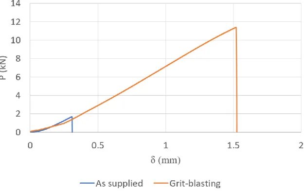
The test used to evaluate both surface treatments was the traction test in mode I. This test consisted in loading in mode I (tensile stresses) two steel blocks that were bonded to the 25 x 25 mm2 specimen with the configuration CFRP-Ti-CFRP, as shown in Figure 31.
The steel blocks had a hole with a 5mm diameter through which a steel pin was introduced connecting the sample to the testing machine’s grips. A loading scheme is presented in Figure 32.
Figure 31 - Bonding between the steel blocks and the specimen CFRP-Ti-CFRP
P
Ti P
CFRP
treatment, the average failure load was 1.69 ± 1.28 kN. Nevertheless, when the composite was bonded to a titanium sheet that was grit-blasted the results were extremely better and the average failure load was 11.40 ± 1.56 kN. These results shown in Figure 33 and the typical failure of the sample for each test pictured in Figure 34 a) and b).
Figure 34 - Typical failure of the samples in mode I traction test: (a) adhesive failure in Ti-CFRP interface; (b) cohesive failure in CFRP (delamination)
Figure 33 – Most representative curve for Mode I traction test
The typical failures in the samples tested were different depending on which surface treatment was applied. In the case where titanium was used as supplied, the failure was adhesive in the interface between the titanium sheet and the CFRP plate. This happened due to the poor adhesion between those materials, which led to the conclusion that using the titanium as supplied was not a possibility. When the mechanical surface treatment was applied, the failure was completely dissimilar. The composite suffered delamination near the interface between the CFRP plate and the steel block. These results showed that the adhesion between the CFRP and the treated titanium was stronger than the one between the composite and the steel. Therefore, the grit-blasting was proven to be a surface treatment that offers satisfactory results and it was chosen to be applied to all titanium sheets.
It was expected that, using the peroxide alkaline etch, the results would be even better than those achieved using the grit-blasting. However, the purpose was to reach a reasonable bond strength between the CFRP and the titanium and not to improve the bond durability. Thus, it was considered that the grit-blasting should be the one chosen for this work.
3.4.4. Manufacture of CFRP-Titanium laminates
The manufacture of the CFRP-Titanium laminates followed the same basic principles than the manufacturing of the CFRP plates described in section 3.4.1. The major difference between the two manufacturing processes is the presence of metal laminates that must be interleaved according to their position within the specimen configuration.
All of titanium laminates used had a 0.8 mm thickness, so to achieve a 3.2 mm of total thickness, it was necessary to stack 16 CFRP layers together for the Ti-CFRP configuration and 8 plus other 8 layers for the CFRP-Ti-CFRP configuration.
In order to understand this procedure, a brief description is done following the main steps to manufacture the CFRP-Ti-CFRP configuration.
I. The first three steps described in section 3.4.1 are followed. However, the number of CFRP layers stacked are not 21 but only 8. At the end there are plates with a 1.2 mm thickness;
degreased again using acetone until it is completely clean;
IV. Subsequently, the protective wax paper coating is removed from the last CFRP layer, and the plate is heated using a hot air gun to improve bonding with the metal laminate. The titanium laminate should be applied, as shown in Figure 35.
V. The remaining CFRP plate are stacked on the top the titanium sheets, with 1.2 mm thickness to complete the specimen configuration;
VI. Once the configuration is completed, the FML is placed in the hot plate press machine and the CFRP cure cycle is carried out. This step is similar to the one described in point IV for the CFRP plates. The mould is prepared in the same way:
VII. Using the model DV 25 Batisti Meccanica, the specimen is cut into the desired shape. For the remaining configuration, Ti-CFRP, the procedure is the same, but the titanium sheet is placed over the 2.4 mm thick CFRP plate (16 layers stacked) and, then transported to the hot plate press for curing.
3.4.5. Manufacture of single lap joints
The manufacture of the adherends was the first stage in the experimental component of this thesis. Subsequently, the single lap joints were manufactured in order to be tested later. These single lap joints were produced with a specific geometry. However, two overlaps were chosen: 12.5 mm and 50 mm. The width of the SLJs was 25 mm. The geometries are presented in Figure 36.
The manufacture of the complete SLJs followed the procedure described below.
I. Using the model DV 25 Batisti Meccanica, the adherends and the alignment tabs of the same material are cut and treated superficially using sandpaper (in a 45° direction to avoid damaging the fibres) and degreased with acetone. In the case of Ti-CFRP, the metallic surface is grit-blasted to a better application of the adhesive and then degreased with acetone.
II. The adhesive in film form, AF 163-2K, is defrosted and cut according to the overlap dimensions, 12.5 and 50 mm, and the dimensions of the alignment tabs, 25 mm. Later, the adhesive is applied in one of the adherends, as shown in Figure 37;
III. The SLJ mould is cleaned and degreased to remove any solid contaminant. Two layers of Loctite® Frekote 770-NC, a release agent, are then applied to facilitate the SLJs’ removal after the adhesive cure. The CFRP’s spacers also receive two layers of the release agent as to be easier to remove;
Figure 37 - Adhesive in film placed on one adherend Figure 36 - SLJs geometry (mm) [55]
IV. The alignment tabs are bonded on the end of each adherend with the same adhesive. Several substrates are positioned in the SLJ mould, followed by the spacers. The two adherends are then bonded carefully so that the single lap joint may be obtained, as shown in Figure 38;
V. The closed mould is transported to the hot plate press and apply the adhesive’s cure cycle is followed;
VI. Afterwards, when the cure is already done, the excess of adhesive is carefully removed using an iron file so that the fibres are not damaged. Then, a sandpaper is applied to finish the cleaning process;
VII. To finish the manufacturing process, the free end of each substrate is drilled slowly, where the alignment tabs are placed in order to make a hole for inserting the dowel pins for gripping purposes. This procedure is done carefully and using a lubricant to avoid high temperatures due to the differences in the thermal expansion coefficient that may cause tension concentrations. The impurities are removed by using acetone degreasing one last time.
![Figure 12 - Typical loads of an adhesive joint: a) Normal stress; b) shear stress; c) cleavage stress; d) peel stress [21]](https://thumb-eu.123doks.com/thumbv2/123dok_br/15139531.1011730/28.892.224.691.131.496/figure-typical-adhesive-normal-stress-stress-cleavage-stress.webp)
![Figure 22 - CZM laws with triangular, exponential and trapezoidal shapes available in Abaqus ® [53]](https://thumb-eu.123doks.com/thumbv2/123dok_br/15139531.1011730/37.892.169.772.563.743/figure-czm-triangular-exponential-trapezoidal-shapes-available-abaqus.webp)